 Contactor,circuit breaker,sensor,Encoder,PLC,Converter

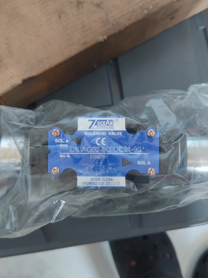

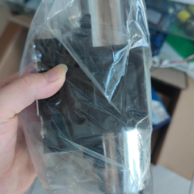
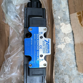
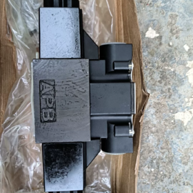
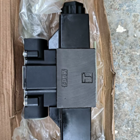
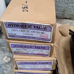
DSV-G02-2C-DC24-90
- DSV: Solenoid directional valve, terminal box type solenoid
(DSD = DIN connector type; identical mounting subplate for both versions)
- G02: Size NG6 / CETOP-03 / D03 (6 nominal diameter)
- 2C: 4/2-way, double solenoid, spring return
Spool function: Spring return initial position; energize one solenoid → P→A, B→T; energize the other solenoid → P→B, A→T
- DC24: Coil voltage DC24V
- 90: Type 90 wet armature high-power solenoid
Suffix options: 20,72,82 represent different solenoid specifications. Solenoids are NOT interchangeable.
- Core Technical Specifications
Mounting Standard: CETOP RP121H, D03 size subplate mounting
Max. Operating Pressure: 35 MPa (350 bar)
Max. Allowable Tank Back Pressure: 22 MPa
Rated Flow: ≤110 L/min
Hydraulic Fluid: Hydraulic oil (ISO VG32 / ISO VG46)
Fluid Temperature: -20 ~ +70℃
Solenoid: DC24V Type 90 wet armature solenoid, 100% continuous duty (ED100%)
Valve Weight: Approx. 2.6 kg
- Key Distinction Points
- DSV vs DSD-G02
DSV: External terminal box (screw wiring) – Model DSV-G02 as specified
DSD: DIN43650 quick plug connector
→ Identical internal flow path; only solenoid wiring housing differs.
- 2C Spool Function
✅ 4/2-way double solenoid spring return; no neutral position. Valve automatically resets to initial position upon power cut.
- Notice for Type 90 Solenoid
Strictly specify suffix -90 during procurement/replacement. Replaced by -20 series solenoid will result in insufficient actuating force, overheating and sluggish shifting.
- Equivalent & Alternative Models
- Original identical unit: DSV-G02-2C-DC24-90
- Alternative wiring version: DSD-G02-2C-DC24-90 (plug type, compatible subplate)
- Domestic compatible equivalent: WF, YUKEN DSG-01-2B2-D24 series
(Close mounting dimension; spool function verification required)
- Typical Fault Diagnosis
- Slow or failed shifting: Undervoltage, mismatched solenoid type, spool seizure caused by contaminated oil
- Coil overheating & burnout: Continuous overload, voltage fluctuation, internal short circuit
- High internal leakage: Spool wear, pressure retention failure
7OCEAN DSV-G02-2C-DC24-90 (NG6 D03 4/2-Way Double Solenoid Valve) Complete Installation Procedure
Applicable to subplate mounted hydraulic solenoid directional valve
DSV: Terminal box solenoid; DC24V Type90 high-power wet armature coil; 2C double solenoid spring return
⚠️ Operators must hold hydraulic & electrical operation qualification. Depressurize hydraulic system and cut off power before any work!
- Pre-Installation Inspection (Mandatory)
1.1 Material Verification
Valve Model: DSV-G02-2C-DC24-90. Confirm voltage DC24V, spool code 2C, solenoid suffix 90
Accessories: Standard G02 subplate (CETOP03/D03), 4pcs M6 hex socket bolts, 4pcs O-rings for P/A/B/T port sealing
Visual check: No valve body impact, coil crack or debris blocking oil ports.
1.2 System & Environment Check
Ambient condition: -20~70℃, relative humidity<90%RH, no condensation; Keep away from heat sources, welding spatter and heavy vibration
Hydraulic oil cleanliness: NAS 8 or superior; install ≥100 mesh filter on suction line
System maximum pressure shall not exceed 35MPa.
1.3 Tools Preparation
M6 hex socket wrench, torque wrench, lint-free cloth, dry compressed air gun, multimeter, insulated screwdriver.
- Subplate & Valve Mounting
Step 1: Clean sealing surfaces (Critical to prevent spool sticking)
- Blow off debris on subplate mounting surface and valve bottom sealing surface with dry compressed air
- Wipe surfaces with lint-free cloth; eliminate iron chips, rubber fragments and residual oil
- Fit 4 O-rings into P/A/B/T recesses on valve bottom. Avoid twisting or dislodging O-rings.
Step 2: Position and fasten valve body
- Place solenoid valve flat on G02 subplate; align P/A/B/T ports between valve and subplate
Port Marking: P=Pressure Inlet, T=Tank Return, A/B=Actuator Working Ports
- Insert 4 M6 bolts and screw manually to ensure full contact without tilting
- Tighten bolts diagonally in 2~3 stages
✅ Standard tightening torque: 5.5~6.5 N·m
❌ Do NOT fully tighten single bolt sequentially. Excessive torque crushes O-rings and causes internal leakage; insufficient torque leads to high-pressure external leakage.
- Recommended mounting posture: Horizontal installation, solenoids arranged left & right horizontally (natural layout for double solenoid). Small tilt angle permitted; long-term inverted installation is not suggested.
Step 3: Connect hydraulic piping to subplate
- Connect hydraulic hoses to threaded ports P, T, A, B on subplate
- Prevent external pulling force on subplate to avoid shear load and sealing leakage
- Max. allowable back pressure on T return line ≤22MPa; keep return piping short with adequate nominal diameter.
- Electrical Wiring (DSV Terminal Box Version, DC24V Coil)
This valve equipped with dual solenoids (left solenoid, right solenoid), DC24V, polarity sensitive!
⚠️ Perform wiring only after power is disconnected. Live wiring prohibited!
- Unscrew terminal box cover and open enclosure
- Each solenoid has independent terminal set:
Terminals for each coil: DC24V(+), DC24V(-); DC coil polarity must be followed
PLC/relay outputs: Two independent control signals. Simultaneous energization of left & right solenoids is strictly forbidden!
- Use copper control cable ≥0.75mm²; securely crimp terminals; avoid loose stray wires causing short circuit
- Route cable properly to prevent tension on terminals; refit terminal box dust cover
- Pre-test with multimeter: Measure resistance of both coils under power-off state. Infinite resistance indicates coil open circuit.
- System Flushing & No-Load Commissioning (Do NOT apply full load pressure directly)
4.1 Initial Flushing
- Confirm all bolts and pipe connections are completed
- Jog hydraulic pump, start under low pressure (3~5MPa), circulate and flush system for 5~10 minutes
- Inspect sealing joints between valve and subplate for external oil leakage. If leakage occurs, depressurize and retighten bolts evenly.
4.2 Electrical Jog Test (Low pressure or zero pressure)
- Maintain low hydraulic pressure
- Energize left and right solenoid separately for short pulses (1~2 seconds each time)
- Normal feedback: Distinct “click” switching sound upon energization
No sound: Low supply voltage, wrong wiring, damaged coil
Abnormal noise / No switching: Contaminated spool; valve disassembly and cleaning required
Safety Rule: Implement interlock in control program to prevent both solenoids energized simultaneously!
4.3 Loaded Gradual Pressure Test
- After successful low-pressure switching, raise working pressure step by step
- Perform repeated reciprocating switching and observe actuator motion:
Left solenoid energized → P→A, B→T
Right solenoid energized → P→B, A→T
Power cut → Spring automatically returns spool to initial position
- Run continuously for 30 minutes for inspection: No leakage on sealing surfaces; normal coil temperature without abnormal overheating.
- Prohibited Operation Rules (Installation Red Lines)
- ❌ Do NOT use solenoid housing as leverage point for prying or clamping valve
- ❌ Do NOT install without removing iron debris on subplate. Scratched sealing surface and spool seizure will occur
- ❌ Exceed torque limit on M6 bolts, which crushes O-rings and triggers continuous internal leakage
- ❌ Long-term reverse polarity of DC24V supply, shortens solenoid service life
- ❌ Simultaneous energization of dual solenoids, results in coil burnout and internal spring damage
- ❌ Blocked T return line or excessive back pressure leading to switching failure
- ❌ Operate system directly with heavily contaminated hydraulic oil.
- On-Site Troubleshooting after Installation
- Oil leakage between valve and subplate: Depressurize and retighten bolts diagonally; check broken or misplaced O-rings
- Unable to switch: Measure coil voltage, verify wiring polarity; clean spool if contaminated oil causes seizure
- Slow switching: Confirm Type90 solenoid is equipped; Type20/72 low-thrust solenoid cannot be substituted; check excessive voltage drop on cable
- Rapid coil overheating and burnout: Long continuous energization (valve supports ED100% continuous operation, but dual coil simultaneous energization forbidden) or over supply voltage.
7OCEAN DSV-G02-2C-DC24-90 Complete Technical Data
- Model Code Definition
DSV-G02-2C-DC24-90
- DSV: Wet armature solenoid directional valve, screw terminal box solenoid
(DSD = DIN quick plug type; identical flow body)
- G02: Mounting standard NG6 / CETOP03 / ISO4401-AB-03-4-A (6 nominal diameter)
- 2C: 4/2-way, double solenoid, bi-directional spring return
De-energized initial position: P↔B, A↔T
SOL.a (Left Coil) Energized: P↔A, B↔T
SOL.b (Right Coil) Energized: P↔B, A↔T
⚠️ Never energize both solenoids simultaneously
- DC24: Nominal control voltage DC24V
- 90: Type90 high-power wet armature solenoid
Greater actuating force for high-pressure applications; not interchangeable with 20/72/82 solenoids.
- Hydraulic Performance Data
| Item | Specification |
| Valve Type | Direct operated wet solenoid directional valve|4/2-way double solenoid spring return |
| Nominal Diameter | 6 mm (NG6 / D03) |
| Max. Operating Pressure (P,A,B Ports) | 35 MPa (350 bar) |
| Max. Allowable Tank Back Pressure (T Port) | 22 MPa |
| Rated Flow | ≤63 L/min (at pressure drop ΔP=1MPa) |
| Recommended Operating Flow | ≤60 L/min. Higher flow causes excessive pressure drop and delayed switching |
| Switching Response Time (DC Coil) | Actuate:10~15 ms; Spring Reset:10~15 ms |
| Max. Switching Frequency | 300 cycles per minute |
| Working Fluid | Mineral hydraulic oil ISO VG32 / VG46 |
| Fluid Kinematic Viscosity | 15~400 mm²/s |
| Required Oil Cleanliness | NAS Class 8 or superior; Filtration ≥25μm |
| Fluid Temperature Range | -20 ℃ ~ +70 ℃ |
| Standard Seal Material | NBR Nitrile Rubber; Optional FKM Fluorocarbon Rubber for high temperature & chemical resistance |
- Electrical Data (Type90 DC24V Solenoid)
| Item | Parameter |
| Rated Voltage | DC24V (Allowable tolerance ±10%, 21.6~26.4V) |
| Coil Duty Cycle | ED=100% (Permitted continuous energization) |
| Rated Power (Single Coil) | Approx. 31 W |
| Coil DC Resistance (20℃) | Approx.18~22 Ω (measured range) |
| Solenoid Construction | Wet armature design, low noise, shiftable under operating pressure |
| Ingress Protection | IP65 (fully assembled terminal box) |
| Wiring Method | Screw terminals in terminal box; polarity dependent for DC |
| Recommended Control Cable | ≥0.75 mm² copper cable |
- Mechanical & Mounting Data
- Mounting Standard
Mounting pattern: ISO 4401-AB-03-4-A (CETOP RP121H / DIN24340 Type A)
Matching accessory: G02 standard subplate
- Fastening Bolts
Specification: M6 hex socket bolts ×4 pcs
Standard Tightening Torque: 5.5~6.5 N·m (Diagonal staged tightening)
- Weight
Complete valve with dual solenoids: 2.05 kg
- Recommended Mounting Attitude
Horizontal installation preferred; tilt allowed; long-term inverted installation not recommended.
- Spool Function Description (2C Spool)
De-energized (Spring Return): P ↔ B, A ↔ T
Left Solenoid SOL.a Energized: P ↔ A, B ↔ T
Right Solenoid SOL.b Energized: P ↔ B, A ↔ T
This is a 2-position valve without neutral position. Spool immediately returns to initial position once any solenoid is de-energized.
- Selection & Distinction Notes
- DSV vs DSD-G02
Identical flow body, mounting dimension and spool function; only solenoid wiring interface differs:
DSV = Screw terminal box wiring; DSD = DIN43650 plug connection.
- Solenoid Suffix: 90 / 82 / 72 / 20
Type90: High thrust version, suitable for high pressure, heavy load and low oil temperature conditions (standard for this model)
Type20/72/82: Standard thrust type. Risk of insufficient shifting force under high pressure; cannot directly replace Type90 solenoid
- Circuit Warning
Control logic must avoid simultaneous output of two switching signals. Dual coil simultaneous energization leads to rapid temperature rise and solenoid burnout. Electrical interlock circuit is mandatory.
- Typical Application Industry
Machine tool hydraulic stations, injection molding machines, automated production lines, woodworking machinery, hydraulic fixtures, lifting platforms, auxiliary hydraulic circuits for construction machinery.





NH42-63-318x560.png "CHINT PC-type automatic transfer switches (ATS)NH42-63/4SZ")



