 Contactor,circuit breaker,solar inverter,electric meter,solar batteries

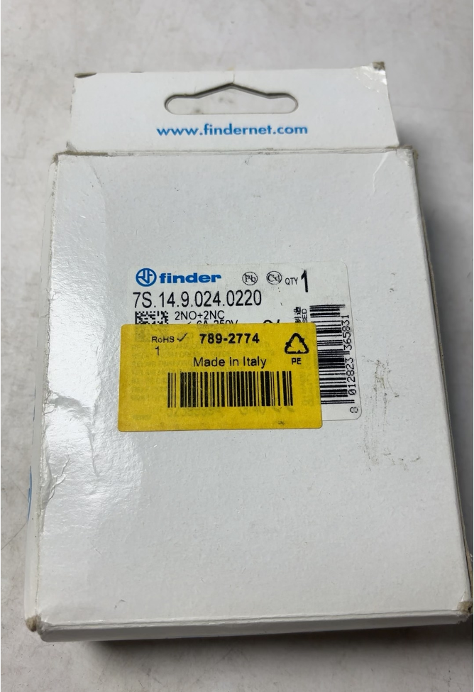

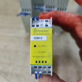
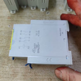
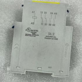
Finder 7S.14.9.024.0220 Forced Guided Contact Safety Relay Module
- Model Code Interpretation
| Segment | Code | Meaning |
| Series Code | 7S | Finder 7S series forced guided contact safety relay module, compliant with EN 50205:2002 Type A |
| Contact Configuration | 14 | 4-pole, 2 Normally Open + 2 Normally Closed contacts |
| Mounting & Terminal | 9 | DIN rail mounting, cage-clamp terminal, 22.5mm width |
| Coil Voltage | 24 | 24V DC control coil |
| Version & Feature | 220 | Standard version without extra functions |
- Core Specification Table
| Category | Parameter | Remarks |
| Basic Info | ||
| Manufacturer | Finder | Famous Italian relay brand |
| Product Type | Forced guided contact safety relay module | Non-latching type |
| Order Number | 7S.14.9.024.0220 / 7S1490240220 | Two formats are both applicable |
| Electrical Parameters | ||
| Coil Voltage | 24V DC | Standard industrial control voltage |
| Coil Power Consumption | 1.2W | Typical value |
| Contact Arrangement | 2NO+2NC (4P) | Forced guided design for synchronous contact operation |
| Rated Current | 6A @ 250V AC (AC-1) | Rated value for different load types |
| 6A @ 30V DC (DC-1) | ||
| 3A @ 230V AC (AC-15) | ||
| Contact Material | AgNi Silver Nickel Alloy | High conductivity and wear resistance |
| Mechanical & Environmental Parameters | ||
| Installation Type | DIN Rail (EN 60715) | 22.5mm compact width |
| Terminal Type | Cage-clamp | Screwless wiring, easy installation |
| Protection Grade | IP20 | Finger-proof, suitable for cabinet interior |
| Operating Temperature | -40°C ~ +70°C | Wide temperature range for industrial use |
| Storage Temperature | -40°C ~ +85°C | |
| Certification | EN 50205:2002 Type A, EN 13849-1 | International safety relay standards |
| Service Life | Mechanical: 10⁷ operations | |
| Electrical: 10⁵ operations at rated load |
- Cross-brand Replacement Reference
| Brand | Model | Similarities | Differences |
| Pilz | PNOZ X2.8P 24VDC | 2NO+2NC, 24VDC, forced guided contact | Professional safety relay, higher price and richer functions |
| Siemens | 3TK2825-1BB40 | 2NO+2NC, 24VDC, DIN rail mount | Better compatibility in industrial automation |
| Schneider | Zelio SR2B121BD | 2NO+2NC, 24VDC, forced guided contact | Different terminal design, cost-effective |
| Omron | G9SA-321-T075 | 2NO+2NC, 24VDC, safety certified | Compact size, ideal for limited space |
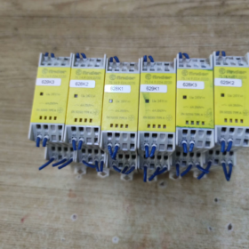
- 7S Series Main Model List
| Model | Contact Layout | Coil Voltage | Terminal Type | Special Feature |
| 7S.12.9.024.0220 | 2P (1NO+1NC) | 24V DC | Cage-clamp | Standard |
| 7S.14.9.024.0220 | 4P (2NO+2NC) | 24V DC | Cage-clamp | Standard (this product) |
| 7S.16.9.024.0220 | 6P (3NO+3NC) | 24V DC | Cage-clamp | Standard |
| 7S.14.9.230.0220 | 4P (2NO+2NC) | 230V AC | Cage-clamp | Standard |
| 7S.14.9.024.4220 | 4P (2NO+2NC) | 24V DC | Cage-clamp | LED status indicator |
| 7S.14.9.024.5220 | 4P (2NO+2NC) | 24V DC | Screw terminal | Standard |
| 7S.34.9.024.0220 | 4P (2NO+2NC) | 24V DC | Cage-clamp | 10A rated current |
- Troubleshooting & Maintenance Guide
5.1 Common Fault Analysis
| Fault Phenomenon | Possible Causes | Inspection Steps |
| Coil fails to pull in | 1. Insufficient or reversed coil voltage | 1. Measure coil voltage to confirm 24V DC |
| 2. Burnt coil | 2. Test coil resistance (normal: approx 480Ω) | |
| 3. Loose wiring | 3. Check terminal tightness | |
| No contact movement | 1. Jammed forced guided mechanism | 1. Check mechanical flexibility after power off |
| 2. Oxidized or burnt contacts | 2. Inspect contact surface damage | |
| 3. Mechanical wear | 3. Verify contact travel distance | |
| Contact sticking | 1. Arc burn caused by overload or short circuit | 1. Check actual load exceeding rating |
| 2. Contact material fatigue | 2. Replace relay module | |
| LED indicator off | 1. Damaged LED | 1. Check power supply connection |
| 2. Power disconnection | 2. Replace with identical module for test | |
| 3. Internal circuit failure |
5.2 Maintenance & Replacement Suggestion
- Safety Priority: Cut off power and wait at least 5 minutes for capacitor discharge before maintenance.
- Modular Structure: On-site repair is not recommended; integral replacement is preferred.
- Replacement Procedure
Record wiring positions by photos or sketches
Remove old module from DIN rail
Install new module and reconnect wires accordingly
Power on and verify normal operation
- Preventive Maintenance
Inspect terminal connection every 6 months
Avoid overload, reserve 30% current margin
Shorten replacement cycle to 2-3 years under harsh conditions
- Application Scenarios & Industry Cases
6.1 Applicable Fields
| Industry | Typical Application | Safety Function |
| Machinery Manufacturing | Emergency stop circuit, safety door monitoring | Prevent accidental startup, protect operators |
| Automatic Production Line | Safety light curtain, two-hand control circuit | Secure operating area safety |
| Elevator & Escalator | Door lock monitoring, safety loop | Avoid unexpected elevator movement |
| Rail Transit | Door control, braking system | Comply with railway safety standards |
| Packaging Machinery | Guardrail monitoring, emergency stop | Personnel injury prevention |
6.2 Inadmissible Working Conditions
High vibration environment such as stamping machines, shockproof bracket required
Humid and dusty environment, IP54+ sealed enclosure needed
Ultra-high frequent switching over 10 cycles per minute, solid state relay recommended
High current load over 6A / 250V AC, contactor required for capacity expansion
6.3 Selection Tips & Avoidance Notes
- Distinguish forced guided contact from ordinary relay; EN 50205 compliant type mandatory for safety application
- Confirm coil voltage, avoid AC and DC confusion; this model is 24V DC
- Match load type with corresponding rated current (AC-1/AC-15/DC-1)
- Reserve enough installation space for 22.5mm width module
- Ensure compliance with EN 13849-1 for industrial safety usage
Application Scenarios of Finder 7S.14.9.024.0220
Equipped with forced guided safety contacts, conforming to EN13849 and EN50205 safety standards, applied for equipment safety loop control.
- General Industrial Machinery
- Machine tools: Emergency stop circuit, safety door interlock, tool magazine safety lock
- Stamping & forging machines: Guard fence detection, slide safety limit
- Injection molding machines: Mold safety door, manipulator area protection interlock
- Automatic Production Line
- Conveyor line: Light curtain safety protection, station access judgment
- Assembly equipment: Two-hand startup circuit, robot fence access control
- Sorting & packaging machines: Flip cover protection, fault emergency stop interlock
- Lifting & Hoisting Equipment
- Small lift, cargo elevator door control safety circuit
- Crane lifting tool limit protection, power-off safety lock
- Light Industry & Special Machinery
- Safety stop interlock for printing and textile machinery
- Safety door monitoring for wood cutting equipment
- Fault power-off protection for fans and water pumps
- Transportation & Building Auxiliary
- Automatic door and escalator safety detection circuit
- Vehicle industrial control, miniature railway equipment safety protection
- Control Cabinet Internal Control
- System emergency power-off safety loop
- High voltage cabinet access control and leakage safety interlock
Unsuitable Environments
Non-sealed cabinet with strong corrosion and heavy dust
Ultra-high frequency switching working condition
Working current exceeding 6A rated load


")
NH42-63-318x560.png "CHINT PC-type automatic transfer switches (ATS)NH42-63/4SZ")


