 Contactor,circuit breaker,sensor,Encoder,PLC,Converter

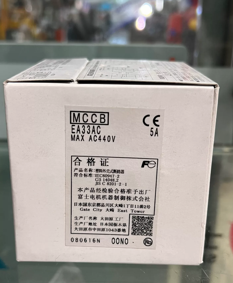
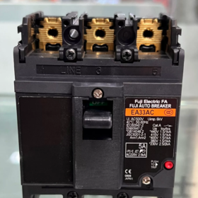
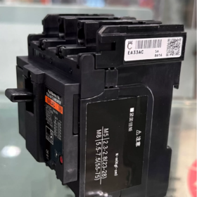
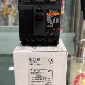
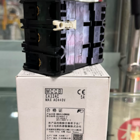
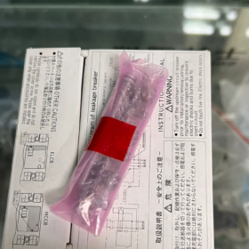
EA33M-3P 32A / EA33AC (The EA33AC variant has no factory 32A rating). EA3AAC3P-32A is a handwritten abbreviation used on drawings & equipment lists. Full Name: Fuji FUJI AUTO BREAKER EA33M 3P 32A Molded Case Circuit Breaker (MCCB)
- Model Code Explanation
EA33: 30AF frame size (maximum rated current 32A for this frame)
M: Standard type, thermal-magnetic trip for power distribution protection
3P: 3-pole, three-phase
32A: Rated operating current In = 32A
Note: EA33AC series maximum rating is only 30A; no genuine 32A version. The 32A variant official designation is EA33M 3P 32A.
- Core Electrical Specifications
| Item | Parameter |
| Model | EA33M 3P 32A (corresponds to drawing abbreviation EA3AAC3P-32A) |
| Poles | 3P, three-phase three-wire |
| Rated Current In | 32A |
| Rated Insulation Voltage Ui | AC415V |
| Rated Operational Voltage Ue | AC220V / AC380/415V |
| Ultimate Breaking Capacity Icu | 2.5kA @ AC220V; 1.5kA @ AC415V (JIS Standard) |
| Trip Unit | Thermal-Magnetic Trip (Long-time delay for overload + instantaneous trip for short circuit) |
| Standards | JIS C8201, IEC60947-2 |
| Origin | Fuji Electric, Japan (Older imported model) |
- Important Information
- Product Status: Discontinued
The EA33 series is an older generation compact MCCB, production permanently terminated by Fuji.
Direct Replacement Model: BW32AAG-3P 32A, identical mounting dimensions and terminal layout, plug-and-play interchangeable.
- Physical Dimensions (W × H × D)
Approx. 75mm × 130mm × 60mm, front wired fixed type.
- Typical Application Scenarios
Three-phase power branch circuits inside small control cabinets, machine tool power circuits, fans & water pump load feeders.
Not suitable for circuits with high prospective short-circuit current (maximum breaking capacity limited to 2.5kA).
- Sourcing & Replacement Recommendation
Second-hand / surplus stock: EA33M-3P 32A (limited availability)
For new projects & equipment retrofitting: BW32AAG-3P 32A (Current production G-TWIN series by Fuji Electric)
Complete Installation Guide for Fuji EA33M 3P 32A (EA3AAC3P-32A)
Physical unit model: EA33M 3P 32A, drawing shorthand EA3AAC3P-32A. Legacy Fuji 30AF MCCB, standard front-wired fixed mounting; cannot directly clip onto 35mm DIN rail.
⚠️ Pre-Work Safety Requirements
- Isolate upstream power supply completely and verify zero voltage before any wiring & installation work;
- Work must be performed by qualified electricians;
- Installation environment: Avoid heavy dust, moisture, corrosive gas and direct sunlight. Ambient operating temperature range: -5℃ ~ +40℃;
- Circuit breaker must be installed vertically (handle moves up and down). Horizontal or inverted mounting is prohibited, which will cause trip mechanism failure.
Part 1: Mechanical Mounting Procedure
- Cutout & Mounting Dimensions EA33M 3P
Overall dimensions: W75mm × H130mm × D60mm
Two bottom mounting holes: φ4.5mm, horizontal hole spacing 54mm; Fastened onto mounting plate with M4 screws.
❗ Critical Note: This model has no built-in DIN rail latch. Direct mounting on standard 35mm DIN rail is impossible. Special adapter bracket required for DIN rail mounting (rarely available on market).
- Mounting Operation
- Place MCCB flat against mounting plate and maintain vertical alignment;
- Tighten upper and lower M4 screws evenly. Do not over-tighten one side to prevent housing deformation;
- After fastening, toggle ON/OFF handle repeatedly to confirm smooth operation without jamming.
Part 2. Electrical Wiring Specification (Front Connection)
- Terminal Definition (Refer to unit marking)
Top Terminals: Line Side (Power Input) → Connect three-phase L1/L2/L3 supply
Bottom Terminals: Load Side (Power Output) → Connect motors & end equipment
✅ Standard Wiring: Supply from top, load at bottom
Warning: Reverse wiring (power fed from bottom) is not recommended for this legacy model. Reverse power supply reduces short-circuit breaking capacity and introduces safety risks during faults.
- Cable Specification & Tightening Torque
Recommended cable size for 32A: 6mm² copper conductor. Use OT/UT cable lugs; bare stranded wires shall not be directly inserted into terminals.
Terminal screw size: M5
Recommended tightening torque: 2.0~2.5 N·m
Insufficient torque → overheating & burnt terminals; Excessive torque → thread stripping, cracked plastic base.
- Wiring Steps
- Control wire stripping length; exposed copper strands shall not extend beyond lugs or contact adjacent phases;
- Cable lugs must fully fit flat against terminal surface. Avoid cable lateral tension applying continuous mechanical load to terminals;
- Wire three phases sequentially and match phase sequence;
- Recheck torque on all terminal screws after wiring completion.
Part 3. Pre-Energizing Inspection Checklist
- Confirm handle positioned at OFF (Open);
- Use multimeter to confirm no inter-phase short circuit and no phase-to-earth short circuit;
- Maintain sufficient clearances between phases; phase barriers shall be installed inside metal cabinets if necessary;
- Clear all metal shavings and loose wire scraps inside cabinet to prevent short circuit.
Part 4. Commissioning & Energizing
- Confirm no personnel working on load side before energizing upstream supply;
- Switch handle to ON position. Watch for abnormal noise, smoke or overheating;
- Run under load for 30 minutes. Check terminal temperature; no abnormal excessive temperature rise indicates acceptable installation.
- Overload & short-circuit tests are only permitted in laboratory environment. Deliberate short-circuit testing on site is forbidden.
Part 5. Critical Prohibited Operations (Common Pitfalls)
- ❌ Forbid horizontal or inverted installation
- ❌ Forbid direct wiring with loose stranded wires without cable lugs
- ❌ Forbid long-term operation with reverse power feed (bottom input)
- ❌ Do not pull cables forcibly to apply mechanical stress to breaker terminals
- ❌ Do not install directly in environments with high humidity & condensation without protective enclosure
- ❗ This model is discontinued with limited spare parts. Replace with BW32AAG-3P32A for new installations (direct size-compatible exchange).
Part 6. Basic Troubleshooting During Commissioning
Instant tripping upon closing: Short-circuit fault on downstream circuit
Tripping after sustained loaded operation: Loose terminals causing heat or load overload
Handle cannot be closed: Internal mechanism seized; breaker damaged, do not strike or force operation
Common Faults, Causes & Solutions for Fuji EA33M 3P 32A MCCB
Equipment Note: EA33M is legacy Fuji 30AF thermal-magnetic MCCB. Long service life commonly leads to aging of mechanical latch and internal bimetallic strip; many faults originate from component deterioration.
Fault 1: Difficult to close / Unable to latch, handle stuck at mid-position
Symptoms
Handle cannot be pushed fully to ON position and fails to stay latched; rebounds immediately after release.
Root Causes
- Trip-free mechanism triggered and not reset
After tripping, the breaker enters trip-free state. The handle must be firmly pushed fully down to the OFF limit position for reset before re-closing.
- Sustained short circuit or severe overload on downstream circuit triggering instantaneous magnetic trip immediately upon closing.
- Long-term aging: internal spring fatigue, latch wear, mechanical jamming.
- Mounting tilt or excessive cabinet vibration causing mechanism misalignment (vertical mounting mandatory).
Troubleshooting Procedure
- Cut upstream power supply, push handle firmly all the way down to OFF limit for reset and attempt closing again;
- Disconnect all load cables on lower terminals, perform no-load closing test:
✅ Successfully closes without load → Fault exists in downstream wiring or equipment
❌ Still fails to close without load → MCCB internal damage, replace unit directly
- Verify vertical mounting; add vibration damping measures if cabinet suffers severe vibration.
Fault 2: Spontaneous tripping after running for a period (Time-delayed tripping)
Symptoms
Starts normally, trips after tens of minutes to several hours of operation, no loud short-circuit bang.
Classification of Causes
- Overload tripping (thermal trip activation)
Continuous operating current near or exceeding 32A; undersized cables, aging motor stall, combined overload of multiple equipment.
- Loose terminals generate heat, heat transfers to internal bimetallic strip and triggers false thermal trip (Most frequent field failure!)
Loose M5 terminal screws due to insufficient torque & vibration → terminal overheating → internal heat conduction causes undesired tripping.
- MCCB aging: Fatigued bimetallic strip, shifted trip characteristic, trips falsely under mild temperature rise.
- Poor cabinet ventilation and excessive ambient temperature.
Remedial Actions
- Measure three-phase operating current with clamp meter to confirm if current exceeds 32A; reduce load or upgrade protection device if overloaded.
- Power off and retighten all terminals to specified torque (2.0~2.5 N·m); replace cable lugs if required.
- Improve cabinet cooling layout; avoid mounting multiple heat-generating components adjacent to each other.
- If frequent delayed tripping occurs under normal load current → breaker aging, replacement recommended.
Fault 3: Instant tripping immediately after closing
Symptoms
Breaker trips instantly upon closing, cannot sustain load connection.
Causes
- Phase-to-phase short circuit or phase-to-earth short circuit on load side (damaged cable insulation, motor winding short circuit)
- Earth fault on load equipment
- Internal inter-phase breakdown inside MCCB (permanent unit damage)
Troubleshooting Flow
- Disconnect all outgoing load cables, perform no-load closing test
Closes normally without load → Fault in downstream cable or motor; test insulation with megger
Still trips instantly without load → Internal breakdown of MCCB, discontinue use and replace immediately
Fault 4: Overheated & discolored connection terminals
Symptoms
Terminal temperature rises significantly during operation, cable insulation softens, terminal surface blackens.
Causes
- Insufficient tightening torque leading to high contact resistance
- No cable lugs fitted, loose stranded wires create poor contact
- Continuous full-load operation with undersized conductors (Minimum 6mm² copper recommended for 32A)
- Oxidation and dust accumulation on terminals.
Remedial Actions
- Isolate power supply, clean oxidation layer, install new OT cable lugs;
- Retighten terminals to specified torque;
- If terminals are severely burnt and plastic base deformed by heat: MCCB must be replaced, continued operation prohibited.
Fault 5: Phase loss / No output on one phase while handle remains closed
Symptoms
Handle shows closed position, voltage present on upper input terminal but no output on lower terminal for one phase.
Causes
Each pole of EA33M has independent contacts. Long-term heating and arc erosion lead to contact separation or partial welding on single pole.
⚠️ Severe Hazard! Visibly closed breaker with open internal phase will easily burn out three-phase motors.
Remedy
Power off and test continuity between upper and lower terminals for each phase. Replace breaker immediately if any phase fails continuity test; on-site repair is not feasible.
Fault 6: Breaker fails to function after short-circuit event
Symptoms
Cannot be closed or runs continuously hot after tripping due to short circuit.
Causes
High short-circuit current creates electric arc, permanently scorching main contacts and damaging internal trip mechanism.
Important Note
EA33M has low breaking capacity (1.5kA @ AC415V). One high-magnitude short-circuit can permanently damage the unit.
✅ Solution: After clearing short-circuit fault, replace the breaker rather than continuing operation with damaged components.
Standard Field Troubleshooting Sequence
- Isolate power supply → Push handle fully down to OFF position for complete reset
- Disconnect all load cables, test breaker performance under no-load
- Locate fault source: Distinguish between downstream wiring/equipment fault and internal MCCB failure
- Damaged breakers cannot be repaired; direct replacement model: BW32AAG-3P 32A (Direct dimensional interchange)
Critical Operational Warnings
- EA33M series has been discontinued. Risk of component aging rises with service time; not recommended as primary protection for critical equipment.
- Reverse wiring (power fed from lower terminals) is not recommended. It reduces short-circuit breaking capacity and increases failure risk.
- Do not strike or pry operating handle forcibly to attempt closing, which may permanently jam internal mechanism.







NH42-63-318x560.png "CHINT PC-type automatic transfer switches (ATS)NH42-63/4SZ")



