 Contactor,circuit breaker,sensor,Encoder,PLC,Converter

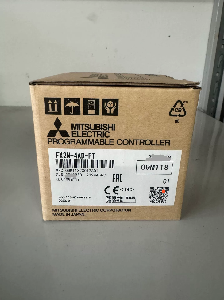
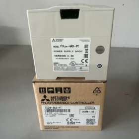
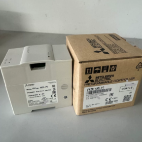
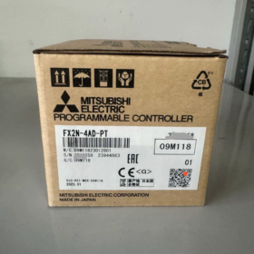
Special expansion module for FX‑series PLC, designed for 4‑channel 3‑wire PT100 platinum‑resistance temperature acquisition. Obsolete (discontinued). Communication is implemented via FROM/TO buffer memory register instructions. 2‑wire PT100 sensors are not supported.
- Model Code Decomposition
| Segment | Description |
| FX2N | PLC series, FX2N expansion module |
| 4AD | 4‑channel analog input |
| ‑PT | Special RTD module for PT100 platinum resistance; not a general‑purpose voltage/current AD module |
- Core Electrical & Technical Specifications
| Item | Specification |
| Supported Sensor | 3‑wire PT100 (100 Ω); module supplies 1 mA constant‑current excitation to sensor |
| Temperature Range | ‑100 ℃ ~ +600 ℃; Fahrenheit: ‑148 ℉ ~ +1112 ℉ |
| Digital Output Format | ℃ mode: value = temperature ×10 (e.g. 25.0 ℃ → 250); ℉ mode: value = ℉ ×10 |
| Resolution | 0.2~0.3 ℃ / 0.36~0.54 ℉ |
| Accuracy | ±1 % of full‑scale range |
| Conversion Time | 15 ms for all 4 channels |
| AD Resolution | 12‑bit (including sign bit) |
| PLC‑side Power Supply | 5 V DC drawn from PLC expansion bus, consumption 30 mA; external 24 V DC for module analog circuit |
| Occupied I/O Points | 8 points (input or output, no physical terminals occupied) |
| Isolation | Optocoupler isolation between analog and digital circuits; no isolation between channels |
| Weight | Approx. 0.3 kg; DIN‑rail mounting |
| Identification Code BFM#30 | K2040; read by program to verify module presence |
| Compatible PLC CPUs | FX0N/FX1N/FX2N/FX2NC/FX3G/FX3U/FX3UC; Not compatible with FX5U |
⚠️ Hard restriction: 2‑wire PT100 is not supported. Forced connection of 2‑wire sensors will cause severe temperature drift and inaccurate measurement. Only 3‑wire RTD is allowed.
- Key Buffer Memory (BFM) List (FROM = Read / TO = Write)
| BFM | R/W | Function Description |
| #0 | W | PT100 standard: K0 = JIS C1604‑1997 (DIN3850); K1 = legacy JIS C1604‑1981 |
| #1~#4 | W | Averaging sample count for CH1‑CH4, range 1‑4096, default = 8; higher value = stronger filtering, slower response |
| #5~#8 | R | Averaged temperature in ℃ for CH1‑CH4 (×10); commonly used in engineering |
| #9~#12 | R | Instantaneous current temperature in ℃ for CH1‑CH4 (×10) |
| #13~#16 | R | Averaged temperature in ℉ for CH1‑CH4 (×10) |
| #17~#20 | R | Instantaneous current temperature in ℉ for CH1‑CH4 (×10) |
| #21 | W | Write K1 to restore factory calibration; register auto‑cleared afterward |
| #28 | R | Channel error latch (wire break, out‑of‑range latch) |
| #29 | R | Error status register (critical); bit‑based alarm flags |
| #30 | R | Module identification code K2040 for program‑side module validation |
Bit Definition of BFM29 for Troubleshooting
| Bit | Fault Description | Remedy |
| b0 | Incorrect parameter setting in BFM#0 | Set BFM#0 to K0 or K1 |
| b1 | Averaging count #1‑#4 out of 1‑4096 range | Modify sample averaging value |
| b2 | Hardware fault, module abnormality | Replace module |
| b10 | Digital value out‑of‑range (sensor wire break / temperature overrange) | Check PT100 wiring; verify burned‑out sensor |
- Wiring Guidelines
- 3‑wire PT100 is mandatory. Three conductors shall have equal resistance and cross‑section as much as possible.
- Use shielded twisted‑pair cables for RTD signal wiring; route separately from high‑power cables to reduce interference.
- Supply module with 24 V DC; reliably ground the FG terminal.
- Never apply voltage signals to PT terminals, otherwise permanent module damage occurs.
- Module number assignment: The first special module adjacent to CPU is Module No.0, counting rightward as No.1, No.2, No.3. The first operand of FROM/TO is the module number.
Simple Ladder Logic Example (Module No.0, read CH1 averaged ℃ value into D0)
FROM K0 K5 D0 K1
D0 = CH1 averaged temperature ×10; e.g. D0=250 equals actual temperature 25.0 ℃.
- Discontinued‑Product Replacement & Upgrade Options
FX2N‑4AD‑PT is obsolete. Solutions grouped by PLC platform.
1) Retain FX3U/FX3UC FX‑family platform
- FX3U‑4AD‑PT: Direct hardware drop‑in replacement, 4‑channel PT100, function‑compatible, FROM‑TO communication unchanged; minor program adaptation required.
Note: FX3U‑4AD‑PT is also gradually phased out.
2) Upgrade to FX5U platform
FX5‑4AD‑PT: RTD temperature module dedicated for FX5U CPU.
Alternative scheme: General analog input module plus external RTD transmitter.
Third‑party compatible replacement
Domestic compatible unit: TX2N‑4AD‑PT. Pin‑compatible with FX2N expansion bus; register mapping identical, allows direct hardware swap.
- Selection Pitfalls & Non‑applicable Conditions
- ❌ 2‑wire PT100 sensors cannot be used.
- ❌ Not for thermocouple inputs (use FX2N‑4AD‑TC for K/J‑type thermocouples; PT and TC modules are non‑interchangeable).
- ❌ No inter‑channel isolation. Common‑mode potential difference among multiple measuring points introduces interference; external isolation required.
- ✅ Typical applications: Ovens, water‑treatment systems, injection‑molding machine barrels, cold storage and other industrial temperature measurement within ‑100~600 ℃.
- High‑interference environments: Increase averaging sample count in BFM1‑4 (set to 16‑32) for digital filtering.
- Common Fault Diagnosis
- Fixed reading at ‑1000 (‑100 ℃) or 6000 (600 ℃): Most likely PT100 wire break or wrong 3‑wire wiring. Check whether BFM29 b10 is set ON.
- Severe temperature drift: Verify equal resistance of three sensor wires; check shield grounding; keep away from power cables.
- All values read zero via FROM instruction: Wrong module number; insufficient 5 V bus power. Read BFM30 identification code to confirm communication.
- Heavy reading fluctuation: Increase averaging sample count in BFM1‑4.
Module distinction reminder: FX2N‑4AD‑PT for PT100 RTD vs FX2N‑4AD‑TC for K/J thermocouples. Hardware cannot be interchanged.
Application Cases of FX2N‑4AD‑PT in Industrial Field
Module characteristics: 4‑channel 3‑wire PT100 RTD acquisition, discontinued. Data exchange via FROM‑TO BFM instructions. Suitable for multi‑point temperature monitoring, alarm handling and PID closed‑loop temperature control for small‑and‑medium‑size equipment. Four practical industrial cases below, including hardware configuration, measuring‑point assignment, process logic, key program snippets, commissioning notes and on‑site risk warnings.
Case 1: Multi‑point Temperature Monitoring for Small Cold Storage / Chiller (Refrigeration Industry)
System Hardware
PLC: FX2N‑32MR; Special module: FX2N‑4AD‑PT (Module No.0)
Sensors: 4 pieces of Class‑A 3‑wire PT100
Measuring‑point assignment
CH1: Cold‑storage ambient temperature
CH2: Evaporator return‑gas temperature
CH3: Condenser outlet‑water temperature
CH4: Chilled‑water outlet temperature
Actuators: 2 compressors, condenser fan, audible‑visual alarm; temperature display via HMI touch‑screen
Process Requirements
- When storage temperature>10 ℃: Compressor 1 starts; temperature>12 ℃: Compressor 1 + 2 run simultaneously.
- When temperature drops to 6 ℃: Stop Compressor 1; temperature drops to 3 ℃: Stop both compressors.
- Alarm triggered for temperature<‑2 ℃ (ultra‑low temperature); sensor wire‑break triggers fault interlock to prohibit compressor startup.
- All temperature values uploaded to HMI; over‑limit event logging enabled.
Key Configuration
- BFM0 = K0 (DIN‑standard PT100); BFM1‑4 = K16 (16‑sample averaging to suppress field interference inside cold storage).
- Read averaged temperature of 4 channels from BFM5~8 (raw value = temperature ×10).
- Read BFM29 for wire‑break and hardware fault detection; interlock compressor shutdown upon fault to achieve equipment protection.
Key Snippet (GX‑Developer Ladder)
M8002 // Initialization pulse
FROM K0 K30 D10 K1 // Read module identification code
CMP K2040 D10 M0 // Compare to validate FX2N‑4AD‑PT
M8000
FROM K0 K5 D0 K4 // Read CH1‑CH4 averaged temperature into D0‑D3
FROM K0 K29 K4M10 K1 // Map error status bits to M10‑M25
Divide D0 by 10 to get actual storage temperature; use ZCP zone‑compare instruction for compressor start‑stop threshold logic.
On‑site Risks
Cold‑storage environment is humid; keep PT100 terminal blocks moisture‑proof. 2‑wire PT100 strictly forbidden due to heavy drift. No channel‑to‑channel isolation; apply single‑point shield grounding when multiple probes share reference ground.
Case 2: Temperature Control for Food Pasteurization Tank (Food‑processing Industry)
Hardware Configuration
PLC FX2N‑64MR; FX2N‑4AD‑PT (Module No.0); FX2N‑4DA analog output module
3 pieces of 3‑wire PT100:
CH1: Material temperature inside tank (PID main control feedback)
CH2: Heat‑exchanger inlet‑water temperature
CH3: Discharge‑port temperature
CH4: Spare channel
Actuators: SSR solid‑state relay for electric heating; circulation pump; discharge diverter valve; closed‑loop PID via FNC88 instruction.
Process Requirements
- Heat material up to 92 ℃ and hold for 15 seconds. Open discharge valve upon setpoint reached; divert unqualified material for recirculation.
- Discharge prohibited when temperature<85 ℃. Immediately cut heating output, trigger alarm and halt system on PT100 wire‑break to prevent dry‑burn hazard.
- HMI displays three temperature readings; process‑data logging to meet HACCP compliance requirements.
Program Highlights
- D0 (CH1 reading) serves as PID PV (process variable, raw value ×10); setpoint SV = 920 representing 92.0 ℃.
- PID output sent to FX2N‑4DA, generating 0‑10 V analog signal to drive SSR power regulation.
- When BFM29 b10 (wire‑break flag) is ON: reset PID output and force‑off heating output Y0.
Commissioning Notes
Heating loop features large thermal inertia & lag; tune P/I/D PID parameters iteratively. Increase BFM1 averaging count to mitigate motor‑caused field noise.
Case 3: Multi‑point Temperature Measurement for Drying Oven in Packaging & Printing Machinery
Hardware
FX2N‑48MR + FX2N‑4AD‑PT
CH1: Oven inlet temperature
CH2: Oven middle‑section (main process control point)
CH3: Oven outlet temperature
CH4: Exhaust air temperature
Actuators: Contactor‑driven heating elements; fan interlock; heating cut‑off upon overtemperature.
Process Logic
- Constant‑temperature control with adjustable setpoint 80‑130 ℃, taking CH2 mid‑oven temperature as main feedback.
- Trigger overtemperature interlock and cut all heating power if outlet temperature>150 ℃; heating activation prohibited if fan is faulty.
- Upload four temperature points to HMI and log overtemperature events.
Engineering Notes
High ambient temperature around oven; deploy high‑temperature‑rated shielded cables for PT100 sensors. Separate signal cables from power cables with minimum clearance ≥20 cm. Install filter on module 24 V power supply.
>⚠️ Not applicable for temperature above 600 ℃ (upper limit of module measuring range). Use FX2N‑4AD‑TC thermocouple module instead for higher‑temperature applications.
Case 4: Temperature Monitoring for Small Chemical Agitated Reactor (Fine‑chemical Industry)
Hardware Configuration
FX2N‑48MR, FX2N‑4AD‑PT; 4‑channel 3‑wire PT100
CH1: Material temperature inside reactor (main control)
CH2: Jacket heating‑medium temperature
CH3: Cooling‑water outlet temperature
CH4: Reactor outer‑wall temperature
Outputs: Heating solenoid valve, cooling‑water solenoid valve, agitator motor, alarm output.
Process Logic
- Open heating valve during heating phase; close heating upon target temperature reached; automatically open cooling‑water valve for over‑temperature protection.
- System enters safe state upon any sensor wire‑break: close heating valve, open cooling water, activate audible‑visual alarm.
- Multi‑channel temperature comparison for alarm on excessive temperature difference between reactor interior and jacket, to avoid local overheating.
Risk Considerations
Corrosive atmosphere inside chemical plant; adopt anti‑corrosion protection sleeves for PT100 probes. No inter‑channel isolation; potential reading fluctuation caused by ground‑potential offset between measuring points; implement single‑end grounding at sensor side.
General Engineering Implementation Rules (Common across four cases)
- Module number verification: The first special module adjacent to CPU = K0, increment to K1/K2 rightwards. The first operand of FROM/TO must match physical module number. Read BFM30 = K2040 to validate hardware configuration.
- Wiring discipline: Use only 3‑wire PT100 sensors. Match three‑wire resistance; single‑point grounding for shield; strictly prohibit voltage injection into sensor terminals.
- Fault‑handling template: Read BFM29 in every scan cycle. b10 ON indicates channel wire‑break. Program shall implement safety interlock rather than alarm only; cut heating output to prevent accidents.
- Reading conversion: Raw register value = actual temperature ×10; e.g. `D0=250 →25.0 ℃`.
- Discontinued upgrade guideline: For existing FX2N system migrating to FX3U: select FX3U‑4AD‑PT. For FX5U migration: adopt FX5‑4AD‑PT.



NH42-63-318x560.png "CHINT PC-type automatic transfer switches (ATS)NH42-63/4SZ")



