 Contactor,circuit breaker,solar inverter,electric meter,solar batteries

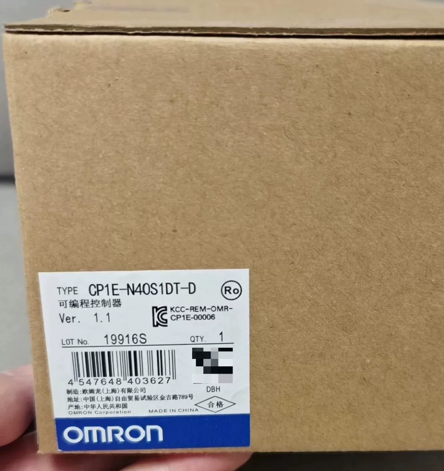

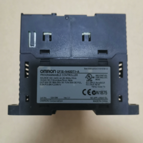
Model Code Breakdown
| Code Segment | Definition |
| CP1E | OMRON compact economical PLC series |
| N | Application CPU: Supports pulse positioning, communication option boards and high-speed counters (E-type models have no pulse output function) |
| 40 | Total built-in I/O: 24 inputs + 16 outputs = 40 points |
| D | Power supply: DC24V power input |
| T | Output type: Transistor output |
| D | Sinking transistor output (Current flows into PLC output terminals from external loads) |
Additional distinction: CP1E-N40DT1-D = Sourcing transistor output. Wiring cannot be interchanged directly.
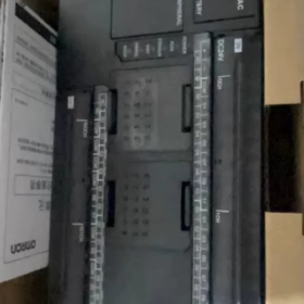
- Core Hardware Specifications
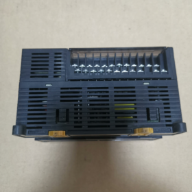
2.1 I/O Configuration
Digital Inputs: 24-point DC24V, 7mA per point, sinking input type; supports 8 interrupt input points
Digital Outputs: 16-point sinking transistor outputs, 0.5A per point, 8 points share one common terminal group; maximum total output current 2A
Expansion Capacity: Up to 3 CP1W expansion modules (digital, analog, temperature modules); maximum total system I/O: 192 points
Built-in 2 analog potentiometers on main unit (Removed on updated model N40SDT-D)
2.2 Operation & Memory Specifications
Program Capacity: 8K steps for Ladder Diagram / Structured Text (ST)
Data Memory (DM): 8K words
High-speed Counter: 4-axis differential phase input (100kHz); supports AB-phase and single-phase pulse signals
Pulse Output: 4 independent high-speed pulse axes (100kHz); supports servo/stepper positioning, origin search and electronic gearing – core positioning feature of N-series CP1E
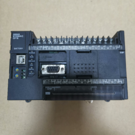
2.3 Communication Interfaces
- Standard Onboard Ports: USB (direct programming connection with PC), RS-232C (for HMI / host computer)
- Expansion Slot: Accepts 1 communication option board (CP1W-CIF01 RS232 / CIF11 RS485 / CIF41 Ethernet)
- Supported Protocols: Modbus-RTU, PLC Link (network up to 9 CP1E units), Host Link
2.4 Electrical & Environmental Parameters
Power Supply: DC24V (20.4~26.4V); total power consumption approx. 15W
Operating Temperature: 0~55℃; Storage Temperature: -20~65℃; Humidity: 10%~90% RH (non-condensing)
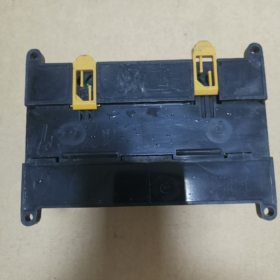
Certifications & Mounting: CE, UL, cULus certified; DIN rail mounting
Dimensions: 150(W) × 90(H) × 85(D) mm; Weight: approx. 900g
- Comparison Between Old & Replacement Models (Official Discontinuation Notice)
Original model CP1E-N40DT-D is gradually discontinued; replacement model: CP1E-N40SDT-D
| Item | CP1E-N40DT-D (Old Version) | CP1E-N40SDT-D (New Replacement Model) |
| Communication Expansion | Supports 1 CIF option board | No expansion slot; only built-in USB + RS232 |
| Analog Potentiometers | 2 adjustable potentiometers onboard | Eliminated |
| Unit Depth | 85mm | 79mm (slimmer design) |
| I/O, Pulse Output, Counter, Program Capacity | Fully identical | Fully identical |
Selection Recommendation:
Retain stock of old model if Ethernet / RS485 expansion options are required.
If only HMI connection and PC programming are needed, directly replace with N40SDT-D. Programs are fully compatible; only communication expansion functions are unavailable.
- Typical Application Scenarios
- Standalone Machine Automation: Packaging machines, conveyor lines, small assembly equipment, injection molding auxiliary machines
- Multi-axis Positioning: Simple multi-axis cutting, drilling and transfer mechanisms with stepper / servo drives (4-axis pulse output)
- Single-station Production Line Control: Assembly line workstations, test fixtures, small warehouse sorting systems
- Environmental Protection Equipment: Small-scale water treatment, logic control of fans and valves for waste gas purification
- List of Commonly Used Matching Expansion Modules
Digital Modules: CP1W-8ER / 16ER (Relay Output), CP1W-8ET (Sinking Transistor Output)
Analog Modules: CP1W-MAD44 (4AI + 2AO), CP1W-MAD11 (4 Analog Inputs)
Temperature Acquisition Modules: CP1W-TS002 / TS004 (Thermocouple), CP1W-PT100
Communication Option Boards (Only compatible with old N40DT-D): CP1W-CIF41 (Ethernet), CIF11 (RS485 Modbus)
- Critical Wiring Rules & Operation Prohibitions
- Sinking Output Wiring: Connect positive pole of load to DC24V, negative pole to PLC output terminal, COM terminal to 0V. Reverse wiring is strictly forbidden and will burn output points.
- Servo Drive via Pulse Output: Pulse signal cables must be twisted-shielded and routed away from power cables to reduce interference and pulse loss.
- Do not share the same switching power supply for PLC main unit DC24V and external sensors, which may cause drift of input signals.
- Program Backup: Built-in lithium battery retains DM data and user programs. Service life approx. 5 years; replace with CP1W-BAT01 upon expiry.
- Troubleshooting Matrix for Common Faults
| Fault Symptom | Root Cause | Solution |
| No pulse output action | Reversed output wiring, COM terminal not connected to 0V, pulse instructions not enabled in program | Verify sinking wiring; check parameters of PULS / SPED instructions |
| Input points permanently ON / No signal input | Missing external 24V power supply, mismatched NPN/PNP sensor type | NPN sensors match sinking input of this PLC; replace sensor or install signal conversion module |
| PLC Link communication failure | RS485 terminal resistor not activated, duplicated station numbers, reversed A/B wiring | Enable terminal resistors on both ends, standardize A/B cable sequence, modify duplicated station numbers |
| Red ERR light flashes after power-on | Program error, short-circuit on expansion module, low battery voltage | Clear program for testing; disconnect expansion modules one by one for inspection; replace lithium battery |
Full Specification of Programming Software for OMRON CP1E-N40DT-D
- Core Programming Software: CX-Programmer (Abbreviated as CX-P)
It is the only official programming tool dedicated to all OMRON PLC series (CP1E/CP2E/CJ/CS etc.), fully compatible with CP1E-N40DT-D.
Minimum Version Requirements
- Basic functions (pulse control, RS485 communication): CX-Programmer V9.03 or higher
- When using CP1W-CIF41 Ethernet option board: Must install V9.12 or higher
- New main units / updated N40SDT-D model: Recommended version V9.6 / V9.73 (included in CX-One V4 series)
- Two Installation Suites (CX-Programmer cannot be downloaded independently)
2.1 CX-One (Full Version, Recommended)
Integrated OMRON automation toolset including all industrial control software:
CX-Programmer (PLC programming)
CX-Simulator (Offline PLC simulation; supports CP1E program emulation)
CX-Designer (HMI programming)
CX-Motion, CX-Protocol, communication drivers and other servo / HMI configuration tools
Suitable for projects requiring simultaneous debugging of PLC, HMI and servo drives.
2.2 CX-One Lite (Compact Version for Micro PLCs Only)
Only contains Micro PLC edition of CX-Programmer, without HMI and servo software. Smaller installation size, exclusively for compact CP1E/CP2E PLCs, ideal for standalone projects requiring only PLC programming.
- Supported Programming Languages (All compatible with CP1E-N40DT-D)
- Ladder Diagram (LD) – Most widely used
- Function Block Diagram (FBD)
- Structured Text (ST) – C-like high-level language
- Sequential Function Chart (SFC) – Step-based process flow
Pre-built function blocks for pulse positioning, high-speed counter and Modbus-RTU are embedded in the software, matching the 4-axis pulse output capability of this PLC.
- PC-PLC Connection Methods (Communication Settings in Software)
- Direct USB Connection (Most Convenient)
Mini-USB port on PLC main unit, standard printer USB cable. Select “USB” as communication type in software; driver-free recognition.
- RS232 Serial Port: Onboard DB9 port for connection with HMI or PC serial port
- RS485 Communication: Install CP1W-CIF11 option board
- Ethernet Communication: Install CP1W-CIF41 Ethernet option board for remote program upload/download
- Auxiliary Supporting Tools
- CX-Simulator: Offline simulation without physical PLC; supports logic debugging, pulse positioning and I/O simulation. Only available in full CX-One package.
- CX-Protocol: Debug custom communication messages between host computer and PLC
- SLM License Manager: Software activation and authorization tool
- General Notes
- CX-One and CX-One Lite cannot be installed simultaneously; only one suite can be selected.
- This software is commercial licensed. Official trial versions with time limits are available; official license purchase is required for long-term use.
- Old CX-P versions V7 / V8 cannot recognize CP1E-N40DT-D and will trigger model mismatch errors.
- When creating a new project, select device type: CP1E → N40DT-D to fully activate 4-axis pulse control, expansion module and communication option board functions.


 Safety Relay")


")
NH42-63-318x560.png "CHINT PC-type automatic transfer switches (ATS)NH42-63/4SZ")


