 Contactor,circuit breaker,sensor,Encoder,PLC,Converter

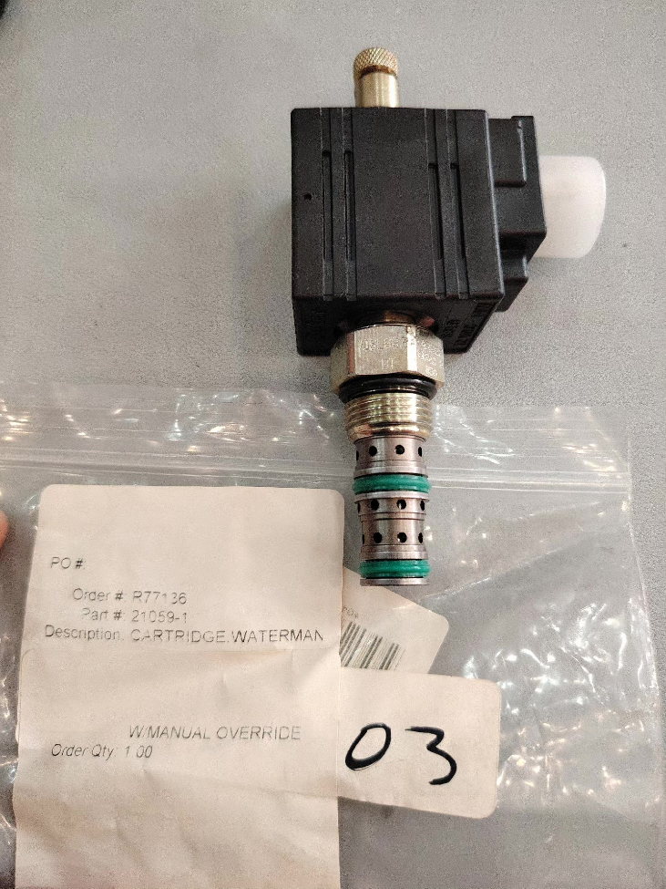

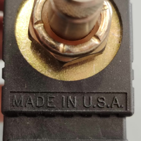
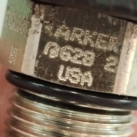
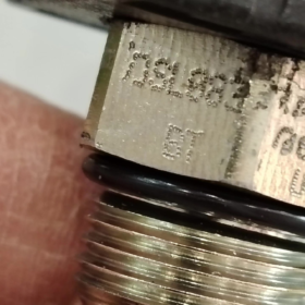
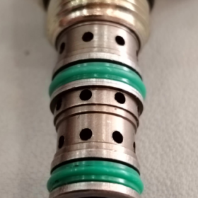
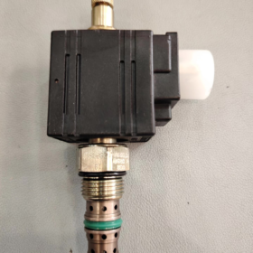
DSL083, 2-position 3-way spool-type threaded cartridge valve with T-option manual override. Cavity C08-3 (3/4-16 UNF-2A thread).
Model Code Explanation
DSL: Low-pressure series spool-type cartridge solenoid valve (250 bar); DSH stands for high-pressure version (350 bar).
08: Size 08, cavity C08-3.
3: 3-way function.
B: B-function (De-energized: port 2-1 connected; Energized: port 2-3 connected, selector normally-closed type).
T: T = Push-twist manual override. No manual operation without suffix T.
Key Technical Specifications
| Item | Specification |
| Function | 2‑position 3‑way spool, spring‑return, with manual override |
| Cavity | C08‑3, thread 3/4‑16 UNF‑2A |
| Max Operating Pressure | 250 bar (3600 psi) |
| Nominal Flow | 15 L/min (4 GPM) |
| Leakage | Approx. 180 cm³/min @250 bar (intrinsic spool leakage) |
| Installation Torque | Cartridge: 31‑37 N·m (23‑27 lb‑ft); Coil nut: 7‑10 N·m |
| Response Time | Approx. 50 ms |
| Fluid | Mineral‑based hydraulic oil, viscosity 6‑420 cSt |
| Filtration Requirement | ISO 4406 18/16/13 |
| Temperature Range | ‑37~+93℃; Standard D‑Ring Nitrile seals |
| Weight | Approx. 0.13 kg |
Port Logic (B-Function)
De-energized (spring position): 2 ↔1 connected, port 3 blocked
Energized (solenoid position): 2 ↔3 connected, port 1 blocked
Typical uses: Circuit selection, pilot switching, motor start-stop, load pilot control. Due to intrinsic spool leakage, not suitable for zero-leak holding circuits.
Coil Information
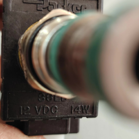
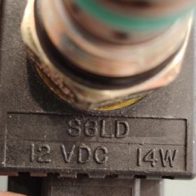
Coil is sold separately. Use Parker Unicoil series coils. Common voltages: 12 VDC, 24 VDC; Electrical connector: DT04-2P automotive-style connector.
Minimum operating voltage: 85 % of rated voltage.
Replacement References
- Parker high-pressure drop-in replacement: DSH083BT (350 bar, same C08-3 cavity, direct interchangeable).
- Domestic alternative: SV08-33B-T (C08-3 cavity, B-function, with manual override). Verify flow, pressure and manual-override construction.
Important Notes
- Spool-type design creates inherent leakage. Add pilot-operated check valve for load-holding applications.
- T-manual override is push-twist style for commissioning and emergency only. Do NOT operate continuously in manual position.
- Strictly follow torque values. Over-torque damages cavity; under-torque increases leakage.
Typical Application Cases for Parker DSL083BT (2-position 3-way B-function Spool Cartridge Valve)
Valve function recap: De-energized: 2-1 connected, port 3 blocked; Energized: 2-3 connected, port 1 blocked; Push-twist manual override; Cavity C08-3, 15 L/min, 250 bar; Intrinsic spool leakage, not for zero-leak holding.
The T-manual override is well-suited for on-site commissioning and field emergency operation.
Case 1: Single-acting Cylinder Lift Control (Mobile Equipment Most Common)
Equipment: Aerial work platforms, agricultural lifting implements, small sanitation vehicles, lifting racks
Circuit arrangement: Port 2 = pressure supply, Port 1 = tank, Port 3 = cap-end of single-acting cylinder.
Operation logic:
1) De-energized: 2-1 connected, cylinder port 3 blocked. Cylinder holds position but drifts slowly over time due to spool leakage.
2) Energized: 2-3 connected, pressure oil extends cylinder (lift). Upon de-energization, load weight drives retraction.
T-override function: For emergency lowering during power-loss faults by activating manual override.
⚠️Note: Install pilot-operated check valve for long-term load holding to compensate spool leakage.
Case 2: Pilot Circuit Switching (Industrial Hydraulic Manifolds)
Equipment: Compact hydraulic power units, fixture power packs, test-bench manifolds
Purpose: Switch pilot supply pressure for relief valves and pilot-operated check valves.
Circuit: Port 2 = pilot supply, Port 1 = tank, Port 3 = pilot signal port of downstream component.
De-energized: Pilot port connects to tank, pilot pressure vented.
Energized: Pilot port receives control pressure to actuate downstream components.
Advantages: Compact manifold-mount design. T-override permits circuit commissioning without electrical power.
Case 3: Pump Unloading / Bypass Switching Circuit
Equipment: Auxiliary injection-molding machinery, balers, small press power units
Port 2 = pump outlet, Port 1 = tank, Port 3 = main system supply.
De-energized: Pump flow directed to tank for low-pressure standby, energy saving.
Energized: Pump supplies pressure to main system for work cycles.
Suitable for intermittent-duty systems. Spool leakage has negligible impact. Manual T-override enables forced unloading for maintenance.
Case 4: Unidirectional Hydraulic Motor Start-Stop
Equipment: Small agitator motors, conveyor drives, rotary actuators
Motor rotates in one direction only; valve controls on-off without direction reversal.
Port 2 receives supply pressure. Energized: pressure fed to motor. De-energized: motor port blocked while supply flows to tank.
Limitation: Motor drifts slowly at stand-still due to spool leakage. Add brake valve for precise positioning.
Case 5: Branch Circuit Selector
Equipment: Multi-station tooling, test benches, select supply to one of two actuators
Port 2 = common supply. Energized selects branch 3; De-energized selects branch 1 to realize two-way circuit selection.
Suitable for medium-low flow switching up to 15 L/min. Manifold mounting reduces external piping.
Case 6: Auxiliary Functions for Off-Highway / Agricultural Machinery
Equipment: Harvester attachments, landscape equipment, drill auxiliary cylinders
Tolerates high vibration and wide temperature range (-37~+93℃). DT automotive-style coil connector provides vibration resistance. T-override enables field emergency operation during power loss.
Not for main high-flow circuits; intended for auxiliary clamping, deflector, baffle and similar small actuators.
Application Pitfalls & Selection Tips for DSL083BT
- ❌Not for zero-leak load-holding: Intrinsic leakage ~180 cm³/min @250 bar. Pilot-operated check valve is mandatory for load holding.
- ✅T-override only for commissioning / emergency. Never leave valve latched in manual mode during normal operation.
- Do not exceed 15 L/min rated flow. Excess flow causes high pressure drop, overheating and unreliable shifting.
- For continuous working pressure above 250 bar, upgrade to DSH083BT (350 bar, cavity-compatible drop-in replacement).
- Coil must be ordered separately; 24 VDC is most common; connector type DT04-2P.
Parker DSL083BT Threaded Cartridge Solenoid Valve Installation & Commissioning Guide
Valve basics: Cavity C08-3, thread 3/4-16 UNF-2A; 2-position 3-way spool with push-twist manual T-override; Cartridge torque 31-37 N·m, coil nut 7-10 N·m; Max flow 15 L/min, 250 bar; Inherent spool leakage.
⚠️Safety prerequisites: Fully depressurize hydraulic system and cut coil power before disassembly / assembly. Never work with pressurized or live electrical components.
- Pre-installation Inspection
- Part Verification
Confirm part number DSL083BT. Inspect D-ring / back-up ring for nicks or damage. Check cartridge threads and hex flats for impact damage.
Order-separate Unicoil coil: match voltage (24 VDC typical), DT04-2P connector, bore size compatible with valve stem.
Verify manifold cavity: C08-3 standard cavity. Threads free of burrs, cavity bore clean of metal chips. Cavity damage causes leakage and spool sticking.
- System Cleanliness
Hydraulic fluid cleanliness target ISO 4406 18/16/13. Flush new manifolds thoroughly. Metal chips or sealant residue inside bore frequently cause spool sticking.
Lightly lubricate seals with system hydraulic oil. Do NOT apply thread sealant onto O-rings or inside cavity; sealant ingress will seize the spool.
- Function Double-Check
DSL083BT B-function: De-energized: 2-1 connected, port 3 blocked; Energized: 2-3 connected, port 1 blocked. Do not confuse with A-function. Mounting orientation is arbitrary, no angular restriction.
- Cartridge Installation Procedure
- Thread cartridge in by hand until seated; do not force-hammer.
- Tighten cartridge hex with torque wrench: 31-37 N·m (23-27 lb-ft)
✅Under-torque: external manifold-to-valve leakage.
❌Over-torque: permanent cavity deformation, spool sticking and excessive internal leakage.
- Fit coil onto valve stem, tighten coil retaining nut to 7-10 N·m. Avoid over-tightening to prevent coil housing damage.
- Engage DT04-2P connector and latch securely. Orient connector downward or sideways to prevent water pooling.
-Electrical note: DC coils recommend free-wheeling diode to suppress inductive kickback and protect PLC outputs. Minimum coil operating voltage = 85 % rated voltage.
- T Push-Twist Manual Override Operating Instructions
DSL083BT T-override is for commissioning and emergency use only. Never latch in manual position for continuous operation.
- Operation: Press inward and rotate clockwise slightly to latch spool in actuated position. Release latch by reverse rotation; internal spring returns spool automatically.
- Perform manual-override test at low system pressure. Do not leave override latched during machine production-run.
- During total power-loss with residual system pressure, T-override can actuate cylinder for emergency movement.
If manual override fails, replace full cartridge assembly. Field disassembly of internal spool is prohibited.
- Step-by-Step Commissioning Procedure
Step 1: No-load low-pressure test (actuator disconnected)
- Confirm correct oil level, vent air from circuit, ensure low return-line back-pressure.
- Set system pressure to 30-50 bar for initial test; avoid full-pressure immediately.
- De-energized test: Verify port 2-1 connection and port 3 blocked. Confirm actuator behaviour matches B-function logic.
- Energized test: Apply rated coil voltage; listen for audible “click” solenoid actuation. Verify port 2-3 connected and port 1 blocked.
- Cycle solenoid 5-10 times; confirm smooth shifting without sticking or abnormal noise. Typical response ~50 ms.
Step 2: Manual-override commissioning
Power off solenoid, keep system at low pressure. Actuate T-override and confirm forced spool shift. Release override and verify spring return to original function. Always return override to neutral position after test.
Step 3: Gradually ramp up to working pressure
After successful low-pressure test, increase pressure step-wise to working conditions. Keep flow ≤15 L/min.
Inspect for external oil seepage at cartridge hex and coil assembly.
Understand spool leakage: ~180 cm³/min @250 bar is intrinsic spool characteristic, not a fault. Pilot-operated check valve required for load-holding circuits.
Step 4: Continuous cycle validation
Cycle valve 20-30 times consecutively. Check coil temperature; warm housing is normal. Excess heat or buzzing indicates incorrect supply voltage.
- Troubleshooting
| Symptom | Probable Cause | Remedy |
| Solenoid energized, valve does not shift | 1. Supply voltage below 85 % rating; 2. Spool jammed by contamination; 3. Failed coil; 4. Over‑tightened coil nut | Measure coil terminal voltage; disassemble and flush manifold cavity; replace coil; adjust coil‑nut torque |
| Wrong function / no spring return in de‑energized state | 1. Contamination spool binding; 2. Fatigued return spring; 3. Cavity deformation from over‑torque | Flush hydraulic system; check installation torque; replace cartridge if needed |
| External oil leakage | 1. Insufficient cartridge torque; 2. Damaged D‑ring seal; 3. Scratched manifold cavity | Retorque to 31‑37 N·m; replace seal kit; inspect / repair manifold cavity |
| High internal leakage, rapid cylinder drift | 1. Cavity damage by over‑torque; 2. Spool wear from fluid contamination; 3. Normal intrinsic spool leakage | Add pilot‑operated check‑valve for holding service; improve fluid filtration; replace worn cartridge |
| Manual T‑override stuck, cannot return | Override mechanical damage or contamination ingress | Do not hammer; replace complete cartridge assembly |
- Maintenance & Prohibited Practices
- Do NOT disassemble cartridge internals. Internal components are precision-matched. Field disassembly renders valve scrap; replace full cartridge on failure.
- Fluid contamination is the primary failure source. Periodically monitor fluid cleanliness and replace filter elements.
- Avoid continuous operation above 15 L/min; excess flow causes high pressure drop, heat and unreliable shifting.
- For continuous pressure >250 bar, select DSH083BT (same cavity, drop-in replacement).
- Operating temperature range: -37~+93℃. Standard NBR nitrile seals. Verify seal compatibility for synthetic hydraulic fluids.





NH42-63-318x560.png "CHINT PC-type automatic transfer switches (ATS)NH42-63/4SZ")



