 Contactor,circuit breaker,sensor,Encoder,PLC,Converter

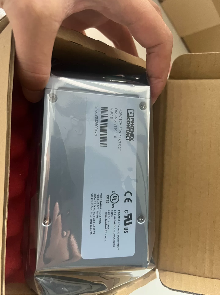

Spelling correction: PHONEX → Phoenix Contact
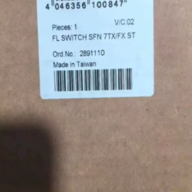
Order-No.: 2891110 | Model: FL SWITCH SFN 8GT
Model Code Decoding
| Code Segment | Meaning |
| FL | Factory‑Line industrial Ethernet switch series |
| SWITCH | Ethernet Switch |
| SFN | Standard Feature Non‑managed switch |
| 8GT | 8‑port Gigabit RJ45 |
Core Hardware & Electrical Specifications
| Item | Specifications |
| Ports | 8 × RJ45 Gigabit (10/100/1000BASE‑T) |
| Switch Type | Unmanaged plug‑and‑play industrial Ethernet switch |
| Power Supply | DC 24 V(18‑30 VDC), dual redundant power inputs |
| Power Consumption | Max. 7.5 W |
| Enclosure | Metal housing, DIN‑rail mountable |
| Operating Temperature | ‑40 ℃ … +70 ℃ |
| Storage Temperature | ‑45 ℃ … +85 ℃ |
| Ingress Protection | IP30 (For cabinet‑internal installation only) |
| Certifications | CE, UL 61010‑1, C‑UL, ATEX, etc. |
| MTBF | Approx. 3.5 million hours |
In-Depth Operating Principle Analysis
This is a Layer-2 unmanaged industrial Ethernet switch:
- Operates automatically after power-on, no configuration software required.
- Internal MAC-address self-learning, wire-speed forwarding for gigabit Ethernet frames between ports.
- Supports Auto-MDI-X; both straight-through and crossover Ethernet cables are applicable.
- Dual power input for power redundancy; the switch keeps running when one power path fails.
- No WEB interface or CLI console; VLAN, QoS and ring-management functions are unsupported.
Installation Dimensions & Wiring Definition
Mounting: DIN 35 mm rail clip-on mounting; screw wall-mounting is also supported
Housing dimension: W 50 mm × H 130 mm × D 115 mm
Power terminals: 2-way spring-cage terminals, `L+` for positive, `M` for negative; two power paths are independent for redundancy.
LED indicators: Link/Act for each port; power-status LEDs.
Wiring Red-Line Warnings:
- Never feed AC 220 V directly into 24 V power terminals.
- IP30 rating: Do not expose to moisture or dust in open-air environments; install only inside control cabinets.
- Connect metal housing to cabinet PE protective earth to suppress industrial EMI interference.
Compatible Replacement Options
| Original OEM Model | Direct‑fit Replacement Model | Remarks |
| 2891110 FL SWITCH SFN 8GT | 2891143 FL‑SWITCH‑SFNB‑8GT | Pin‑to‑pin hardware compatible; new‑generation housing; direct DIN‑rail interchangeable |
| FL SWITCH 1008N (2701497) | Cost‑effective 8‑port gigabit unmanaged switch; minor dimensional difference; DIN‑rail mountable |
⚠️Risk Notice: Verify installation clearance and power consumption for replacement units. Prioritize model 2891143 for retrofitting legacy projects for full pin compatibility.
Package Contents
Standard Delivery Items:
- FL-SWITCH-SFN-8GT Host Unit ×1
- Pre-installed DIN-rail mounting clip
- Paper installation manual
Items NOT included (order separately):
24 V DC power supply
Spring-cage terminal plugs
Ethernet cables
Typical Application Scenarios
- Control cabinet-internal gigabit networking for PLCs, servo drives and HMI panels (packaging machinery, machine-tool industry).
- Aggregation switch for distributed field I/O modules on production lines.
- Local area network inside cabinets for photovoltaic energy storage, port automation and rail-transit equipment.
❌Non-applicable scenarios: Projects requiring VLAN segmentation or ring-network redundancy. Select managed switches such as FL SWITCH 2xxx series instead.
Model-Selection Pitfall Guide
- This is an unmanaged switch without ring redundancy or VLAN functions; do NOT select this model for ring-topology requirements.
- Operating temperature: -40~+70 °C. Maintain adequate clearance for heat dissipation in high-temperature cabinets; avoid stacking multiple units inside enclosed narrow compartments.
- Copper-port-only gigabit unit; no optical ports. Select variants with SFP slots if fiber extension is needed.
Phoenix Contact 2891110 (FL SWITCH SFN 7TX/FX-ST) Application Cases
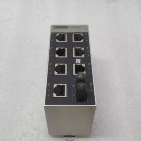
Product Overview: 7 × RJ45 100 Mbps copper ports +1 × ST multi-mode 100 Mbps fiber port, unmanaged DIN-rail industrial switch. Core values: Optical-electrical conversion, long-distance fiber extension, plug-and-play zero-configuration.
Case 1: Automotive Component Assembly-Line Cabinet (PROFINET Field-Level Aggregation)
Operating Conditions: Assembly line located approx. 800 m away from central control room. Heavy EMI from frequency converters; multiple servo drives, vision cameras, HMI panels and distributed I/O units. Twisted-pair copper cable is limited to 100 m, so fiber optics are required for galvanic isolation and long-distance transmission.
Hardware connection: 7 RJ45 ports connect PLC, 3 sets of servo drives, HMI, 2 vision-inspection units and remote I/O modules. ST fiber port links to multi-mode fiber for uplink to central main switch.
Selection Justification:
- Unmanaged zero-configuration; pre-commissioned units can be deployed directly inside cabinets.
- ST multi-mode fiber provides high EMI immunity and eliminates common-mode interference from power cables.
- Narrow 50 mm DIN-rail housing for space-constrained control cabinets.
- PROFINET Class-A compliant; QoS prioritizes real-time control frames.
Boundary Note: 100 Mbps only, suitable for process-control traffic. Select gigabit models for high-bandwidth high-resolution vision streaming.
Case 2: Water-Treatment Plant Field PLC Substation (Interconnection Between Underground Pump-Houses and Central Control Room)
Operating Conditions: Decentralized pump-houses across the plant; pump-house cabinets are 600-1200 m away from central control building. Humid environment with wide temperature fluctuation; heavy EMI from high-power pump motors.
Network Topology: One 2891110 deployed in each pump-house cabinet. RJ45 ports connect local PLC, flow meters, water-quality analyzers and gateways. ST multi-mode fiber provides point-to-point uplink back to central-control-room switch.
Solved Pain Points:
- Copper cables cannot cover long plant-wide distances. Fiber provides galvanic isolation and eliminates ground-loop interference.
- 0~60 °C operating range accommodates seasonal cabinet-temperature variation inside pump-houses.
- No software configuration required; on-site maintenance staff do not need professional networking expertise.
Note: Multi-mode ST fiber maximum transmission distance approx. 2 km. Use single-mode fiber port variants for longer distances.
Case 3: Metallurgical Steel-Plant Auxiliary Workshop (Dust-Removal & Conveyor-Equipment Cabinets)
Operating Conditions: Steel-plant auxiliary lines, heavy dust and strong electromagnetic interference. Multiple local cabinets located 500-900 m from main control room; Modbus-TCP and EtherNet/IP protocols deployed.
Deployment: DIN-rail mounting inside local cabinets. 7 copper ports connect PLC, frequency converters and temperature-acquisition modules. ST fiber port uplinks to main control room.
Key Selection Points: Robust metal-aluminum housing, high EMC immunity compliant with EN 61000-6-2. Alarm relay contacts can feed into cabinet PLC for switch-fault alarm acquisition.
❌Non-applicable: High-temperature melting zones inside steel plants (ambient >60 °C). Upgrade to SFNT wide-temperature variant (-40~+75 °C).
Case 4: Utility Tunnel / Pipe-Gallery Monitoring Sub-Cabinets
Operating Conditions: Segmented field cabinets deployed along utility tunnels. Cabinets host environmental-monitoring PLCs, fire-alarm gateways and camera NVRs; fiber cascading back to control center.
Deployment: One 2891110 installed per tunnel-segment cabinet. RJ45 ports connect field acquisition devices. ST fiber port performs segmented fiber cascading.
Constraint Reminder: This is an unmanaged switch with no ring-network redundancy. Do not form fiber rings directly; use managed FL SWITCH 2xxx series for ring self-healing requirements. Only point-to-point star-topology fiber uplinks are allowed.
Case 5: Large Automated Warehouse (Peripheral Sorting-Unit Cabinets)
Operating Conditions: Sorting zones of high-bay warehouses approx. 700 m away from central server room. Large quantity of barcode scanners, sorting-line PLCs and pallet-position sensors.
Deployment: DIN-rail installation inside sorting-unit cabinets. 7 copper ports aggregate field Ethernet devices. ST fiber uplinks to core switch in server room for surge isolation from high-power equipment.
Advantages: Plug-and-play operation, standardized hardware across sorting-unit cabinets; unified BOM reduces spare-part types.
Model-Selection Lessons from Real-World Projects
- Fiber port supports only 100 Mbps, ST multi-mode, max. distance approx. 2 km. Gigabit traffic cannot pass through this port. Do not connect gigabit-capable devices expecting gigabit throughput.
- Unmanaged unit: No ring support, no VLAN, no STP. Only star-topology point-to-point uplinks permitted. Never build fiber rings.
- Keep ST fiber connectors dust-protected; install dust caps on unused ports. Dust causes frame loss and intermittent link dropouts.
- Power supply range: 9-32 VDC. Never connect AC 220 V. Mandatory PE earthing of metal housing for EMI suppression.
- Standard-model operating temperature 0~60 °C. Select Order-No. 2891047 (SFNT wide-temperature variant, -40~+75 °C) for sub-zero or over-60 °C ambient conditions.
Compatible Replacement List for Equivalent Operating Conditions
| Original Model 2891110 | Replacement Model | Difference Description |
| FL SWITCH SFN 7TX/FX‑ST | 2891097 FL SWITCH SFN 7TX/FX | SC‑type fiber connector; all electrical parameters identical; replace fiber patch‑cords accordingly |
| 2891047 FL SWITCH SFNT 7TX/FX ST‑C | Wide‑temperature rating ‑40~+75 °C for extreme hot/cold environments; fully pin‑compatible |
Phoenix Contact 2891110 (FL SWITCH SFN 7TX/FX-ST) Field Troubleshooting Checklist
Device specification: 7 × 100 Mbps RJ45 copper ports +1 × ST multi-mode 100 Mbps fiber port, unmanaged industrial switch with fault-alarm relay output.
Pre-requisites: Power-supply range 9-32 VDC. Metal housing must connect to PE protective earth. ST multi-mode fiber only; gigabit unsupported.
LED Indicator Definition
| LED | Status | Meaning |
| PWR1 / PWR2 | Solid green | Corresponding power path OK; OFF = power‑path loss |
| LINK/ACT (Copper Port) | Solid | Link established; Blinking = data transmission/reception; OFF = no link |
| LINK/ACT (FX Fiber Port) | Solid green | Fiber link established; Blinking = fiber data traffic; OFF = fiber link down |
| FAULT (Fault) | Solid red | Alarm relay activated; OFF = device normal |
FAULT Relay: Passive dry-contact relay. Relay triggers upon power-supply loss OR any port link down. Can connect to PLC digital-input channel for system-level alarming.
Fault 1: Unit completely unpowered; all LEDs OFF
- Measure DC voltage across terminals `L+` and `M`. Confirm voltage within 9-32 VDC. Verify correct polarity; reverse polarity is prohibited.
- At least one of dual redundant PWR1/PWR2 must be powered. Zero power on both paths leads to complete shutdown.
- Inspect spring-cage terminals for tight torque; check for loose strands causing short-circuit.
- Boundary condition: Overtemperature protection triggers shutdown if cabinet ambient exceeds 60 °C. Maintain ≥20 mm clearance for ventilation. Avoid stacking inside sealed compartments.
❗Red-Line Warning: AC 220 V connected to power terminals will permanently destroy hardware.
Fault 2: Power LEDs ON, but all port LINK indicators OFF
- Copper ports: Use verified-good 100 Mbps-rated Ethernet cable. Auto-MDI-X is supported.
- Force remote-device port speed setting to 100 Mbps full-duplex. Do NOT force gigabit. Mismatched gigabit-forced negotiation will prevent link-up.
- Fiber port: Remove ST connector and clean fiber end-face; remove dust cap if left installed. Confirm multi-mode fiber is used. Single-mode fiber cannot activate this optical transceiver.
- Fiber TX-RX crossover requirement: Switch TX must connect to remote-unit RX; switch RX must connect to remote-unit TX. Mis-wiring results in zero fiber link.
Fault 3: Copper-port traffic random frame loss, intermittent link-up-down
- EMI mitigation: Separate power cables (inverters, motor power wires) and Ethernet cables with ≥20 mm physical clearance.
- Ensure solid PE protective-earth connection of metal housing. Poor earthing induces common-mode noise causing random packet loss.
- Copper-cable length limited to max. 100 m. Inspect crimp quality of RJ45 plugs. For shielded cables: apply single-end shielding earthing.
- Do not connect gigabit-forced devices. Force remote-port setting to 100 Mbps auto-negotiation or 100 Mbps full-duplex.
Fault 4: FX fiber-port no LINK; copper ports operate normally
- Confirm 50/125 or 62.5/125 multi-mode ST-terminated fiber. This port does not support single-mode fiber.
- Clean fiber end-faces. Dust is the No. 1 root-cause for field fiber-port faults. Fit dust caps to unused fiber ports.
- Validate TX-RX crossover wiring: Switch TX ↔ Remote RX.
- Distance validation: Max. reach approx. 2 km for 62.5/125 multi-mode 100BASE-FX. Links will fail beyond this distance.
- Transceiver health test: Apply short fiber loop-back plug to local fiber port. If FX-LINK LED lights, local transceiver hardware is intact; fault lies in external fiber infrastructure.
Fault 5: FAULT red LED stays ON alarm, but network communication remains functional
FAULT relay trigger conditions: Any port link down OR loss of one redundant power supply. This alarm does NOT equal hardware failure.
- Inspect LINK/ACT LEDs of every copper and fiber port; identify ports with missing link.
- Check PWR1/PWR2 power LEDs to identify any lost power path.
- Repair faulty cables/fiber for down-state ports. No software function available to suppress unused-port alarms on this unmanaged switch. Remove cables from unused ports to clear persistent FAULT alerts.
Important Note: Unmanaged hardware cannot disable per-port alarms. Unwired ports continuously trigger FAULT status, which is expected behavior.
Fault 6: Partial devices unreachable; inter-port communication failure
- Layer-2 plug-and-play switch with default full port-to-port forwarding. No VLAN configuration capability.
- Verify all end-devices reside within identical IP subnet.
- Check local firewall settings on PLCs and connected hosts for packet filtering rules.
- Prevent network loops: Never create closed-loop topology via copper or fiber cables into this switch; broadcast storms will crash the whole network.
Strictly-Forbidden Field Operations (Red-Line Taboos)
- Do not connect remote devices forced to gigabit speed. This hardware is strictly 100 Mbps copper ports; negotiation failure occurs.
- Do not deploy single-mode fiber to this multi-mode optical port: No link establishment, potential optical-transceiver damage.
- Always fit dust caps on unused ST fiber ports. End-face contamination causes high failure rate.
- Alarm relay is passive dry-contact. Never apply AC 220 V directly to relay terminals. Only connect to DC 24 V PLC input circuits.
- IP30 rating: For cabinet-mount use only. No open-air, wet-environment installation.
- Do not stack multiple switches inside air-tight narrow cabinets. Overtemperature will cause throttling or protective shutdown.
Quick On-Site Diagnostic Workflow (For Field Technicians)
- Inspect PWR LEDs: Confirm at least one power-supply path is active.
- Inspect FAULT LED: Red-on → Locate lost power path or link-down port.
- Copper-port fault troubleshooting: Swap known-good cable; force remote-port to 100 Mbps full-duplex.
- Fiber-port fault troubleshooting: Clean ST end-face; verify TX-RX crossover; confirm multi-mode fiber type.
- Validate PE earthing; separate power and signal cabling to resolve random packet-loss symptoms.




NH42-63-318x560.png "CHINT PC-type automatic transfer switches (ATS)NH42-63/4SZ")



