 Contactor,circuit breaker,solar inverter,electric meter,solar batteries


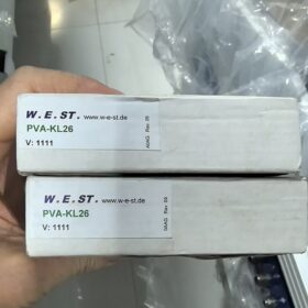
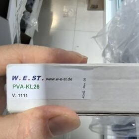
PVA-KL26: KOPPEN & LETHEM Digital Signal Module / Relay Module
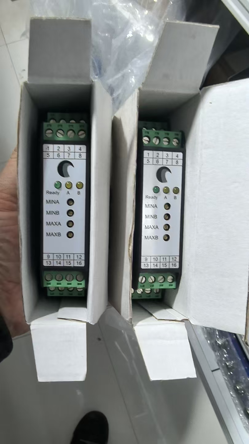
The PVA-KL26 is a 12/24 VDC digital signal module / relay module manufactured by KOPPEN & LETHEM of the Netherlands. It is widely used in industrial control and marine applications, integrating a plug-in LED status indicator and RC circuit (for arc suppression and voltage transient protection).
Core Features
| Parameter | Specification |
| Manufacturer | KOPPEN & LETHEM (sometimes associated with Doedijns) |
| Operating Voltage | 12/24 VDC (wide‑voltage design) |
| Core Functions | Signal conversion, switching control, status indication |
| Key Components | Plug‑in LED indicator, RC circuit (arc suppression) |
| Mounting Style | Plug‑in design for quick installation, removal and maintenance |
| Application Fields | Industrial automation, ship control systems, hydraulic equipment control |
Product Advantages
- Intuitive Status Monitoring: LED indicator displays real-time operating status, reducing the risk of misoperation
- Circuit Protection: Built-in RC circuit effectively suppresses arcing and voltage transients, extending service life
- Easy Installation: Plug-in design saves maintenance time and cost
- Environmental Adaptability: Suitable for harsh industrial and marine environments
Typical Applications
The PVA-KL26 is commonly used for:
Signal conversion and control in marine automation systems
Remote control circuits for hydraulic machinery
Status monitoring and alarm systems for industrial equipment
Relay contact protection and signal amplification
Notes
- Ensure the supply voltage is within 12-24 VDC to avoid overvoltage damage
- Observe correct polarity during installation to prevent damage to the LED indicator and internal circuits
- The RC circuit must be matched to the load for optimal arc suppression
- For use in dry, dust-free environments only; additional protection is required in humid conditions
PVA-KL26 Detailed Technical Specification Manual
(KOPPEN & LETHEM Digital Signal / Relay Module)
The PVA-KL26 is a 12/24 VDC digital signal module / relay interface module specially designed by KOPPEN & LETHEM (Netherlands) for industrial and marine environments. It integrates status indication and arc suppression functions, ideal for signal conversion and control under harsh operating conditions.
- Core Electrical Parameters
| Parameter | Value | Remarks |
| Operating Voltage | 12/24 VDC (wide‑voltage compatible) | Polarity protection, reverse‑connection resistant |
| Control Input Signal | 24 VDC logic level | Compatible with standard PLC digital outputs |
| Contact Rating | 2 A @ 24 VDC / 1 A @ 250 VAC | Resistive load; derate for inductive loads |
| LED Indicator | Plug‑in red LED | Lights up when powered, clear status visibility |
| RC Arc Suppression Circuit | Built‑in standard RC network | Suppresses contact arcing and voltage transients, extends contact life |
| Insulation Resistance | ≥ 100 MΩ (at 500 VDC) | Between input‑output‑ground |
| Dielectric Strength | 1500 VAC for 1 minute | Between input‑output‑ground |
| Power Consumption | < 1 W | Low power, suitable for continuous operation |
- Mechanical & Physical Characteristics
| Parameter | Value | Remarks |
| Mounting | Standard 35 mm DIN rail mounting | Snap‑in design for easy installation/removal |
| Module Dimensions | W 22.5 mm × H 90 mm × D 60 mm | Standard DIN rail module size |
| Weight | Approx. 80 g | Lightweight, saves cabinet space |
| Connector Type | Plug‑in terminal block | Accepts 2.5 mm² wire, tool‑free wiring |
| Ingress Protection | IP20 | For indoor control cabinet use |
| Housing Material | Flame‑retardant ABS plastic | UL94 V‑0 rated, high fire resistance |
III. Environmental & Operating Conditions
| Parameter | Value | Remarks |
| Operating Temperature | −25 °C ~ +70 °C | Wide temperature range for marine/industrial use |
| Storage Temperature | −40 °C ~ +85 °C | Safe storage under extreme temperatures |
| Relative Humidity | 5% ~ 95% (non‑condensing) | Adaptable to high‑humidity marine environments |
| Vibration & Shock | IEC 60068‑2‑6 / IEC 60068‑2‑27 | Complies with marine and industrial anti‑vibration standards |
| EMC | EN 55011 / EN 61000‑6‑2 | Immune to electromagnetic interference, suitable for industrial automation |
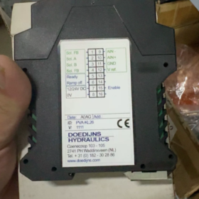
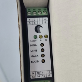
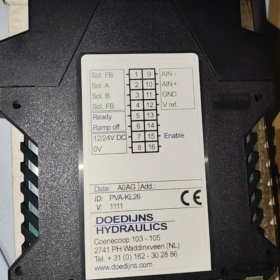
- Pin Configuration & Wiring Definition
(Standard 6-pin terminal block)
| Pin No. | Function Definition | Wiring Description |
| 1 | V+ (Positive Power) | Connect to 12/24 VDC positive |
| 2 | V− (Negative Power) | Connect to 12/24 VDC negative / GND |
| 3 | IN (Signal Input) | Connect to control signal (24 VDC active high) |
| 4 | COM (Common) | Relay contact common terminal |
| 5 | NO (Normally Open) | Closed when relay is energized |
| 6 | NC (Normally Closed) | Closed when relay is de‑energized |
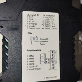
- Detailed Functional Features
- Arc Suppression Technology
Built-in RC snubber circuit (standard: 100 Ω / 0.1 μF) absorbs back EMF from inductive loads at contact break, effectively suppressing arcing and extending contact life by 3-5 times.
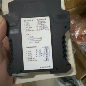
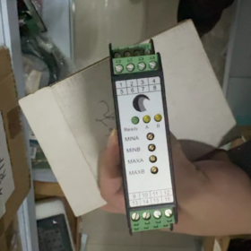
- Status Monitoring System
Red LED provides real-time module status indication
Simple fault diagnosis: LED off = power fault; LED on but no contact action = internal circuit fault
- Safety Design
Polarity protection prevents damage from reverse power connection
Overcurrent protection guards against output short circuits
Surge voltage suppression protects internal electronic components
- Application Limitations & Notes
Load Type Adaptation
Inductive loads (motors, solenoid valves): recommended derating to 50% of rated value
Capacitive loads (capacitors, lamps): current-limiting resistor required to prevent inrush current
Installation Specifications
Avoid installation near heat sources (> 70 °C)
Maintain at least 5 mm clearance around the module for heat dissipation
Ensure secure wire crimping during wiring to prevent poor contact
Maintenance Guidelines
Regularly check LED status and terminal tightness
Insulation test recommended every 6 months in harsh environments
Replace the entire module if faulty; internal repair is not recommended
VII. Alternative Models & Compatibility
| Alternative Model | Brand | Compatibility Description |
| PVA‑KL26‑EX | KOPPEN & LETHEM | Intrinsically safe version for hazardous areas |
| RM22UA02 | Schneider Electric | Functionally compatible, slight dimensional differences |
| DILM25‑10 | Siemens | Higher contact capacity, usable as alternative |
PVA-KL26 Standard Pin / Terminal Configuration
This module uses a 6-pin plug-in screw terminal block.
When facing the front of the module with terminals downward, terminal numbers are 1 to 6 from left to right.
| Terminal No. | Marking | Function Description |
| 1 | IN+ | Positive digital control signal input (24 VDC) |
| 2 | IN− | Negative signal input / common ground |
| 3 | V+ | Positive operating power (12/24 VDC) |
| 4 | V− | Negative operating power / GND |
| 5 | NO | Normally open relay output contact |
| 6 | COM | Relay contact common terminal |
Important Notes
- This model has only NO (normally open) contacts, no NC (normally closed)
- Input with reverse polarity protection; LED lights when IN+ is active
- Built-in RC snubber on output allows direct driving of inductive loads such as solenoids and coils
- Terminal suitable wire cross-section: 0.5-2.5 mm²


")
NH42-63-318x560.png "CHINT PC-type automatic transfer switches (ATS)NH42-63/4SZ")


