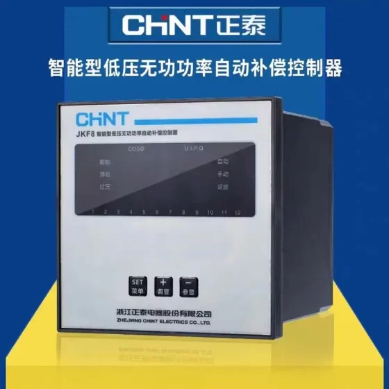
Contactor,circuit breaker,sensor,Encoder,PLC,Converter





PAXS: Strain Gauge / Load Cell input model
0000: 85–250 VAC AC power supply version
DC variant: PAXS0010 (11–36 VDC)
Basic Specifications
Brand: Red Lion (now part of HMS Networks), Made in USA
Form Factor: 1/8 DIN panel mounting (cutout size: 92×45 mm)
Display: 5-digit red LED, 0.56″ (14.2 mm), sunlight-readable; range: -19999 ~ 99999
Input: Strain bridge input; selectable range ±24 mV / ±240 mV; compatible with load cells, strain pressure transducers and torque sensors
Power Supply: 85–250 VAC, 50/60 Hz, power consumption 11 W
Front Panel Protection: IP65
Certifications: UL, cUL, CE, RoHS, UKCA
HS Code: 9030337000; ECCN: EAR99; 2-year factory warranty
Key Functions
- 16-point linearization correction for non-linear load cell calibration
- Front-panel keypad programming (DSP/PAR/F1/F2/RST); parameters stored in EEPROM with power-off retention
- Up to 3 plug-and-play optional expansion cards for field upgrades:
Relay setpoint card (alarm & control output)
Analog transmitter card (4–20 mA / 0–10 V)
Communication card: RS232 / RS485 Modbus, Profibus‑DP
- Custom engineering unit labels (kg, N, t, MPa, etc.)
Typical Applications
Weight monitoring, force measurement, pressure & torque monitoring; silo weighing, material testing machines, press-fit force monitoring.
Cross Reference for the Series
PAXS0000: AC-powered strain gauge meter (current model)
PAXS0010: DC-powered strain gauge meter
PAXP0000: 4–20 mA process input meter
PAXI0000: Counter/frequency meter
PAXT0000: Thermocouple/RTD temperature meter
Spare Parts & Alternatives
Optional add-on cards: PAXCDS10, PAXCDC500, PAXCDL10, etc.
Upgrade Replacement: New-generation PAX2S0000 (PAX2 series, dual-line color display with enhanced functions)
PAXS0000 Red Lion | On-Site Calibration with Standard Weights + Signal Source ADC Calibration + Fault Troubleshooting Checklist
Preconditions: 30-minute power warm-up; confirm PCB jumpers: input range (±24 mV / ±240 mV), excitation voltage (5 V / 10 V); complete sensor wiring (EXC+, EXC-, SIG+, SIG-, shield); parameter lock released (unlock first if locked)
Keypad Functions:
DSP = Back / Display Toggle | PAR = Confirm / Next Item | F1 = Up | F2 = Down | RST = Zero Reset
- Two-Point Field Calibration with Standard Weights (Recommended for Weighing & Force Measurement)
This is Scaling (Span & Zero Calibration), NOT internal ADC factory calibration.
9-FCS is ADC reference calibration, factory-set only; only re-calibrate after meter drift or mainboard replacement (access with CODE 48). Do NOT run this step for regular on-site weighing.
- Zero load: Ensure no weight on the platform, no mechanical binding; connect shield with single-point grounding; wait for stable reading.
- Press PAR repeatedly to enter the menu, open the INP input module, configure:
Input range (24 mV / 240 mV), excitation voltage, decimal point, engineering unit
- Open the SCAL scaling menu
Zero (ZERO): No load, press PAR to confirm zero; wait for —- and save the zero offset
Span (SPAN): Apply standard weights (≥70% full scale). Once stable, edit the displayed value to match the actual weight of the test weights, then press PAR to save span gain.
- Exit the SCAL menu; repeat zero-load and full-load testing 2~3 times. Re-calibrate if deviation is large.
- Optional: LIN 16-point linearization calibration (for non-linear load cells or high-precision press-fit curve testing; input load and corresponding reading point by point)
- After calibration, set a security password to lock parameters against accidental changes.
- Internal ADC Reference Calibration (9-FCS, CODE = 48, Service Use Only)
Only perform this if the meter drifts, mainboard is replaced, or ADC reading is suspected inaccurate. Skip this step for normal field weighing.
- Enter menu 9-FCS, enter password 48, press PAR to confirm.
- Select the active input range (±24 mV or ±240 mV).
- Zero point: Set signal source output to 0 mV across SIG+ and SIG-, press PAR and wait for —-.
- Full-scale point: Output the corresponding full-scale signal (20 mV for 24 mV range / 200 mV for 240 mV range; do not exceed full range). Press PAR and wait approx. 10 seconds.
- When NO appears, press PAR twice consecutively to exit the menu.
- Reconnect the load cell, then re-run the weight-based SCAL scaling calibration above.
- Restore Factory Defaults
Locate the dEF menu and confirm the reset.
⚠️ All calibration data, alarm settings and communication parameters will be erased; full re-calibration is mandatory after reset.
- Fault Troubleshooting Checklist (PAXS0000)
- No Display
Check supply voltage: 85–250 VAC; verify terminal voltage, live/neutral polarity and loose terminals
Check internal fuse on the meter
Distinguish from parameter lock (LOC): LOC only blocks parameter editing, not power-up display
Faulty power board; replace the meter
- LOC Locked, Cannot Enter Menu or Edit Parameters
Parameter security lock enabled; enter the unlock password
If password is lost: restore factory defaults (all calibration data will be lost)
- OL / UL Alarm (OL = Over Range; UL = Under Range)
Load cell overloaded, impacted, or load exceeds full scale
Broken excitation wire, open SIG+/SIGwire, open bridge circuit inside the load cell
Incorrect jumper selection (240 mV range selected while signal is only 24 mV, or vice versa)
Short-circuit of load cell or damaged signal cable shorted to ground
Span value set too small during scaling
- Unstable Reading, Jitter & Drift (High-Frequency Fluctuation)
Shield wire missing; multi-point grounding; signal cable routed alongside power cables causing EMI interference
Oxidized or loose wiring terminals
Unstable excitation voltage; load cell creep or cell damage
Filter parameter FLT set too low (fast response); increase filter time
Mechanical binding on the weighing platform, tight limit stops, loose base mounting
Water ingress or dampness inside junction box
- Zero Drift, Cannot Zero with No Load, Permanent Zero Offset
Auto zero tracking ZTRK disabled; enable zero tracking (do not set large tracking values for heavy force measurement, which will cancel out real load readings)
Uneven mounting or eccentric loading on the load cell
Moisture inside junction box causing unbalanced bridge resistance
Cold calibration without sufficient warm-up (temperature drift)
Fatigue damage of the load cell
- Incorrect Readings After Loading, Poor Linear Performance, Drift After Calibration
Calibration performed with insufficient test weight (less than 70% FS), amplifying scaling error
Non-linear load cell; enable 16-point LIN linearization correction
Wrong excitation jumper (5 V / 10 V mismatch), leading to mV/V conversion error
Excessive cable resistance from long wiring without 6-wire remote sense compensation
Drifted bridge resistance due to damaged load cell
Interference from faulty expansion cards (transmitter / communication card)
- Relay Output Card (PAXCDS10) Fails to Trigger
Incorrect setpoint (SP) and hysteresis (HYST) configuration
Wrong NO/NC output mode setting
Poor card contact; power off, remove and re-seat the expansion card, clean the slot contacts
Load voltage exceeds relay contact rating
- Inaccurate 4–20 mA Analog Output (PAXCDC500 Transmitter Card)
Analog zero & span must be calibrated separately, independent of weighing scaling; perform dedicated AO calibration
Loop load resistance exceeds max. 750 Ω; open circuit in current loop
Damaged analog output card; replace the card
- Modbus RS485 Communication Failure (PAXCDL10 Card)
Mismatched address, baud rate, parity and slave ID between meter and PLC
Missing termination resistor; A/B signal wires reversed
Meter parameter locked; locked versions switch communication to read-only mode
Cross-check Modbus register addresses against the official manual
- Error Codes Err1 ~ Err4
Err1: ADC input fault → Run 9-FCS CODE48 reference calibration first; failure indicates mainboard hardware damage
Err2: Expansion card communication fault → Remove cards one by one and test individually; clean slot contacts
Err3: EEPROM memory checksum failure → Parameter corruption; restore factory defaults and re-program all settings
Err4: External digital input short-circuited
- Standard On-Site Troubleshooting Sequence
- Power off; inspect all wiring, shielding and measure bridge resistance across EXC and SIG terminals with a multimeter
- Power on and warm up for 30 minutes; check zero-load reading
- Verify jumper settings (excitation voltage & input range)
- Check filter and zero-tracking parameters
- Re-run two-point SCAL weight calibration
- If fault persists, perform 9-FCS ADC reference calibration
- If calibration still fails: replace load cell or swap the meter for testing
Important Note
Red Lion USA does not manufacture load cells. PAXS series meters only accept external strain bridge sensor signals. There are no original Red Lion load cell models.
- Red Lion Strain Gauge Meter Product List (PAXS Compatible Models)
PAX Series (1/8 DIN Panel Meters)
- PAXS0000: AC-powered strain gauge meter (your current model), 85–250 VAC
- PAXS0010: DC-powered strain gauge meter, 11–36 VDC
- PAX2S0000: New PAX2 color display model (replaces legacy PAXS)
LD Large-Display Strain Meters (Long-Distance Viewing)
- LD2SG5P0: 2.25″ digit strain gauge input
- LD4SG5P0: 4″ digit strain gauge input
FlexEdge DA Strain Input Modules (DA70/DA75 Controller Expansion)
- DAM00PDSG2RA0000: Dual-channel strain input module with relay output, for weight, force and pressure bridge sensors
Obsolete Discontinued Models
- IMS03162: Older strain panel meter (end-of-life)
- Compatible Load Cell Models (Directly Matched with PAXS0000)
All listed models are mV/V strain bridge type, 350 Ω nominal bridge resistance, 2.0 mV/V nominal sensitivity, 4-wire / 6-wire connection, compatible with 5 V / 10 V excitation from the PAXS meter.
- Mettler Toledo
SBC Cantilever (hopper & platform scale)
MT1041 Single-point (small bench scale)
MT1240 Single-point
SB Cantilever
0745 Column Load Cell
TSH Tension Load Cell
- Celtron (Vishay)
LSD Single-point
SQB Cantilever
STC S-type Tension/Compression (widely used for press-fit force testing)
HBB Cantilever
- Zemic
H3F Single-point bench scale
B3G S-type Tension/Compression
HM8 Column Load Cell
L6E Single-point
- HBM (Germany)
S40 S-type Tension/Compression
Z6FC3 Single-point Bench Scale
C16A High-capacity Column Cell for Silo Weighing
- Transcell
BSS S-type Tension/Compression
FSSB Single-point
CBS Cantilever
- Cost-Effective Domestic Alternatives
Bengbu Load Cells: S-type, cantilever, column, spoke type
Ningbo Keliu: SQB, BSS, DBS, PST series
III. Mandatory Selection Criteria for PAXS0000 Load Cells (Avoid Calibration Errors)
- Signal Type: mV/V strain bridge only; 4–20 mA transmitters require PAXP meter instead
- Bridge Resistance: Preferred 350 Ω; 120 Ω is also supported but limits parallel cell quantity
- Sensitivity: Standard 2.0 mV/V; 1 mV/V or 3 mV/V can be set directly in meter scaling
- Excitation Voltage: Match meter jumper (5 V / 10 V) with the cell rated excitation
- Wiring: 6-wire remote sense recommended for long cable runs (zero drift suppression); 4-wire acceptable for short distances
- Full-Scale Output: Ensure full-scale mV output falls within meter range (±24 mV / ±240 mV)
Example: 2 mV/V cell + 10 V excitation = 20 mV full output → select ±24 mV range (most common setup)
- Recommended Application Combinations (Field-Proven Solutions)
- Press-fit & force-testing fixtures: S-type cell (STC / B3G / S40) + PAXS0000 + PAXCDS10 relay card
- Small bench checkweigher: Single-point cell (L6E / MT1041) + PAXS0000
- Hopper & silo weighing: Cantilever SQB / column cell + PAXS0000; calculate total bridge resistance for multiple parallel cells


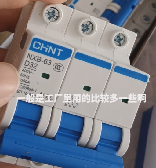
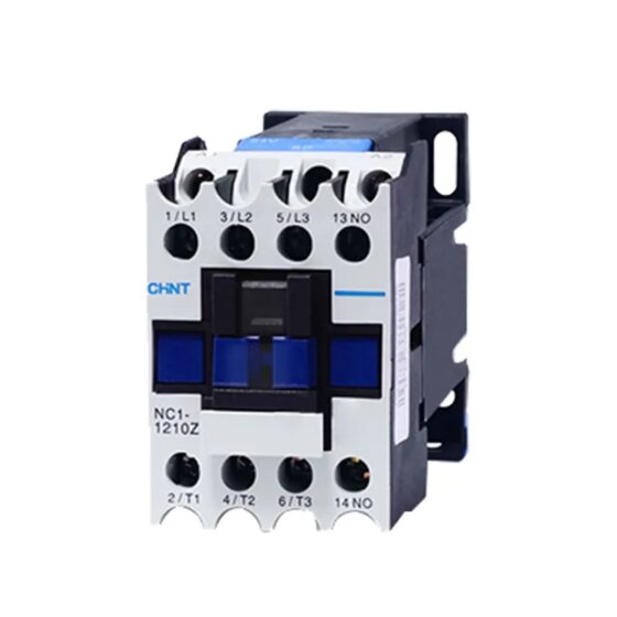
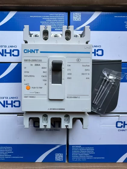
NH42-63-318x560.png "CHINT PC-type automatic transfer switches (ATS)NH42-63/4SZ")