 Contactor,circuit breaker,sensor,Encoder,PLC,Converter

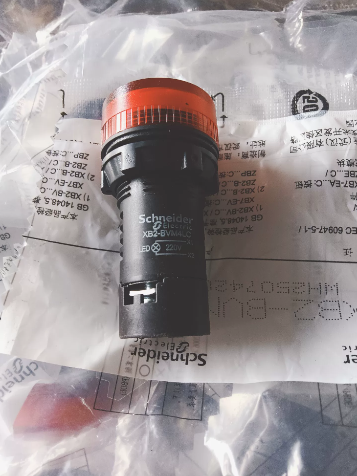
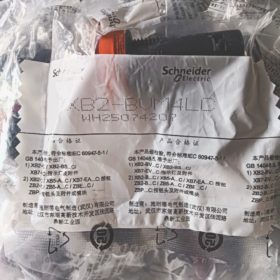
Model Code Explanation (XB2-BVM4LC)
| Model Segment | Definition |
| XB2 | Harmony XB2 Series – 22mm Standard Pushbutton & Pilot Light Range |
| B | Integrated complete pilot light (head and base as one unit, no assembly required) |
| V | Pilot Light |
| M | LED light source, AC 220~230V 50/60Hz AC version |
| 4 | Light head color: Red |
| LC | Factory version complying with Chinese standards, plastic threaded mounting base |
Supplementary color codes for the same series:
1 = White, 3 = Green, 4 = Red, 5 = Yellow, 6 = Blue
Suffixes for voltage differentiation:
M: AC 220V
Q: AC 380V
B: AC/DC 24V
D: DC direct current
- Core Technical Specifications
2.1 Electrical Ratings
Rated Voltage: AC 220~230V, 50/60Hz
Allowable Voltage Fluctuation: 0.8~1.1×Us (176V~253V)
Operating Current: Approx. 20mA
Light Source: High-brightness monochromatic LED, filament-free, long service life
Overvoltage Category: Class I
2.2 Mechanical Mounting Dimensions
Panel Cutout: Standard Φ22.5mm
Mounting Method: Secured via rotating plastic lock nut; compatible with control cabinet panels of 1~6mm thickness
Head Appearance: Round convex lens cover
2.3 Protection & Environmental Specifications
Ingress Protection: IP66 (front dustproof and waterproof); IK05 impact resistance
Operating Temperature: -25℃ ~ +55℃
Storage Temperature: -40℃ ~ +70℃
Applicable Altitude: ≤2000m, no power derating required
Compliance Standards: IEC60947-5-1, GB/T14048.5, CE, RoHS, REACH
2.4 Service Life Metrics
LED Electrical Service Life: ≥50,000 hours of continuous illumination
Vibration Resistance: 15g (40~2000Hz)
- Structure & Wiring Instructions
3.1 Terminal Definition
The base is equipped with only 2 wiring terminals X1 and X2, non-polarized for AC supply
X1: Live wire L
X2: Neutral wire N
AC circuits have no polarity; connecting the two terminals to any position of a 220V circuit will light up the red pilot light.
3.2 Mounting Procedures
- Drill a Φ22.5mm round hole on the control cabinet panel, insert the pilot light body from the front side of the panel;
- Fit the lock nut onto the rear side and tighten manually for fixation;
- Connect control wires to terminals X1 and X2 on the base, then fasten wire clamping screws;
- Switch on power to test steady illumination.
- Application Scenarios
- Standard application for red lights: Equipment fault alarm, emergency stop circuit indication, overload warning, shutdown alert;
- Compatible equipment: PLC control cabinets, air compressors, machine tools, production lines, water pump & fan control boxes;
- Circuit Type: Mains AC 220V control circuit, no intermediate transformer required.
- Cross-Series Selection Reference Table
| Model | Color | Rated Voltage | Application Scenario |
| XB2-BVM1LC | White | AC 220V | Standby, power-on indication |
| XB2-BVM3LC | Green | AC 220V | Normal equipment running status |
| XB2-BVM4LC | Red | AC 220V | Fault, shutdown, alarm |
| XB2-BVM5LC | Yellow | AC 220V | Ready state, pre-alert warning |
| XB2-BVM6LC | Blue | AC 220V | Manual/Auto mode differentiation |
24V low-voltage alternative model: XB2-BVB4LC (Red, 24V AC/DC)
- Troubleshooting Matrix
| Fault Phenomenon | Root Cause | Solution |
| No illumination after power-on | 1. No 220V supply in circuit; 2. Loose wire terminals; 3. Burnt LED chip | Measure circuit voltage with multimeter; retighten wiring terminals; replace the complete pilot light assembly |
| Flickering light with unstable brightness | Voltage exceeds 0.8~1.1 times rated value, poor wire contact | Stabilize supply voltage; re-crimp connecting wires |
| Severe overheating of pilot light | Long-term overvoltage operation, circuit leakage | Verify input voltage; inspect circuit insulation integrity |
| Internal short circuit caused by water ingress into panel | Loose lock nut, oversized panel cutout damaging IP66 performance | Tighten lock nut fully, seal gaps on panel cutout |
- Safe Operation Specifications
- Strictly prohibit direct connection to 380V supply, which will burn out the LED instantly; select XB2-BVQ4LC for 380V circuits;
- Recommended wire: 0.75~1.5mm² solid copper wire;
- Install cabinet sealing gaskets for humid control cabinets and outdoor enclosures to maintain IP66 protection;
- Designed solely for status indication, unable to carry high-power loads; no contact output function;
- Do not strike or grind the lens cover; scratches will drastically reduce light transmittance and protection performance.
- Order & Packaging Information
Individually packed per unit; standard packaging: 5 pieces per small box, 100 pieces per carton
Spare Parts: No separate LED chip spares available; replace the complete pilot light assembly if damaged
Conclusion on Color Replacement for Schneider XB2-BVM4LC (XB2BVM4LC)
- Official Factory Conclusion: The lens cover and LED color cannot be replaced separately
- The XB2-BVM series adopts an integrated non-detachable sealed structure (lens cover, colored LED chip, 220V current-limiting circuit and base housing are integrally injection-molded).
- Schneider official FAQ clearly states: The internal LED module of integrated XB2 pilot lights cannot be disassembled separately, and colored lens covers or LED components are not sold as separate spare parts. Only illuminated pushbuttons with split bases support LED core replacement; this all-in-one light does not allow color component replacement.
- Illumination principle: The lens cover itself is transparent, with a built-in red LED chip (color is not generated via colored filter lenses). Even if the lens cover is forcibly unscrewed, the internal light source remains red and color modification is impossible.
- Two On-Site Color Modification Solutions
Solution 1: Direct Full Unit Replacement (Recommended, Compliant, Factory Standard)
Purchase complete units of target color with the same AC 220V voltage; no wiring modification required, compatible with standard panel cutouts:
White: XB2-BVM1LC
Green: XB2-BVM3LC
Yellow: XB2-BVM5LC
Blue: XB2-BVM6LC
Replacement Steps: Cut off power → Loosen rear lock nut on panel → Remove old red light → Install new colored pilot light → Tighten lock nut and restore wiring.
Solution 2: Temporary Emergency Fix (Only for short-term maintenance, not recommended for long-term equipment operation)
- External colored film: Attach high-temperature resistant translucent colored film to lens surface. Drawbacks: Reduced light transmittance, accelerated aging due to heat, degraded IP protection rating;
- Translucent colored spray coating inside lens cover: Permanently destroys factory IP66 protection rating; water vapor ingress easily triggers short circuits and fails equipment acceptance standards.
- Distinction Between Two Easily Confused Products (To Avoid Wrong Selection)
- XB2-BVM Integrated Pilot Light (This Model): Non-replaceable color, integrated encapsulation, no separate LED core spares;
- XB4 Series Pilot Light / XB2 Split Illuminated Pushbutton: Modular design with separately replaceable LED heads for free color switching, suitable for cabinets requiring frequent color adjustments.
- Supplementary Notes
- Mandatory voltage matching: The original XB2-BVM4LC is rated AC 220V; only models with suffix M (220V) are acceptable for replacement. Models with suffix B (24V) or Q (380V) cannot be used;
- Safety standards compliance: Red/Green/Yellow pilot lights on industrial equipment correspond to fault/Running/pre-alarm status. Unauthorized long-term color modification via film violates machine tool and power distribution safety standards and will fail acceptance inspection;
- Spare Parts Procurement: No separate lens or LED spares; only complete pilot light assemblies can be ordered as replacements.





NH42-63-318x560.png "CHINT PC-type automatic transfer switches (ATS)NH42-63/4SZ")



