 Contactor,circuit breaker,sensor,Encoder,PLC,Converter

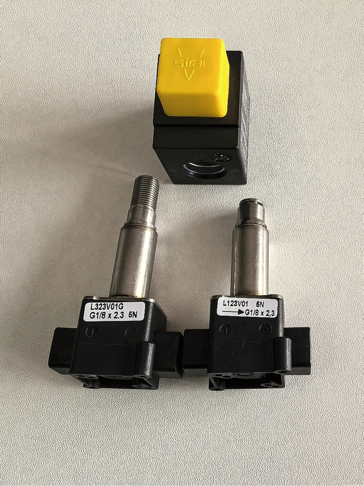

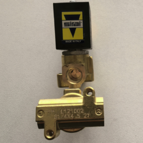
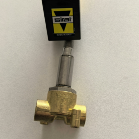
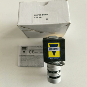
Basic Model Definition
Brand: SIRAI (now owned by ASCO Emerson, original Italian manufacturer)
Model: L323V01G
Function: 3/2 Direct-Acting Normally Closed (NC) Mini Solenoid Valve Body (Coil Not Included; ZA/ZB Series Coils to Be Ordered Separately)
- Core Technical Specifications
Fluid Structure Parameters
| Parameter Item | Specification |
| Circuit Configuration | 3-Way 2-Position, Normally Closed (NC) |
| Actuation Type | Direct-acting (No pilot; reliable actuation at low pressure) |
| Port Thread | G1/4 Female Thread (ISO228/1) |
| Orifice Diameter | 1.5 mm |
| Flow Coefficient Kv | 0.08 m³/h |
| Valve Body Material | OT58 Brass |
| Standard Seal | NBR Nitrile Rubber (FKM Fluoroelastomer / EPDM Optional) |
| Max Medium Viscosity | 37 cSt (5°E) |
Pressure Range
Max Static Pressure Rating: 40 bar
Operating Pressure Differential for AC Coils: 0 ~ 16 bar
Operating Pressure Differential for DC Coils: 0 ~ 10 bar
Temperature Range
Medium Temperature: -10℃ ~ +90℃
Ambient Temperature: -10℃ ~ +50℃ (Max 60℃ for Class F Coils; Max 80℃ for Class H Coils)
Electrical Matching (Coil Not Included with Valve Body)
Compatible Coil Models: ZA10A, ZB10A, ZA13A, ZB14A, etc.
Standard Voltages:
AC: 24V/50Hz, 110V, 220/230V 50Hz
DC: 12V, 24V
Ingress Protection: IP67 when fitted with standard DIN connector; 100% ED (Continuous energization without coil burnout)
- 3/2-Way Operating Principle
- De-energized (Normal Closed State): Inlet Port 1 is sealed; Port 2 communicates with exhaust Port 3 for pressure relief.
- Energized (Open State): Solenoid pulls plunger; flow path 1→2 opens, exhaust Port 3 is closed.
Applications: Pneumatic direction switching, vacuum gripping, small air circuit shutoff, water spray control.
- Compatible Media & Industrial Applications
- Applicable Media: Compressed air, nitrogen, clean water, diluted coolant, non-corrosive inert gas.
NBR is incompatible with oil and high-temperature steam; select FKM seal version for corrosive media.
- Typical Applications
Mini pneumatic directional valves for automation equipment
Water circuit control for small washers and humidifying spray systems
Small air circuit shutoff for packaging machines & textile machinery
Laboratory instruments & miniature vacuum circuit control
- Model Selection & Matching Guidelines
- Complete Order Model Format: L323V01G-ZA10A 230VAC (Valve Body + Coil + Rated Voltage)
- Seal Upgrade: Custom valve bodies with FKM fluoroelastomer seals available for high-temperature / oil-water working conditions.
- Alternative Models: Same series L323V02G (Normally Open NO), L323V03G Universal Type
- Mounting Requirements: Mountable at any angle. Install a 40–100 mesh filter upstream of piping to prevent plunger jamming by contaminants. Only wrap the last two rear threads of male pipe threads with PTFE tape to avoid debris entering the valve chamber.
- Common Troubleshooting Matrix
| Fault Phenomenon | Root Cause | Remedial Action |
| No switching when energized | Burned coil, mismatched voltage, pressure differential exceeds 10 bar for DC | Replace matching coil; reduce pipeline pressure differential |
| Persistent leakage after shutdown | Contaminants on plunger, aged seals | Disassemble and clean plunger; replace NBR/FKM seal kit |
| Coil heats up rapidly | Incorrect voltage selection, long-term excessive pressure differential, damaged coil insulation | Verify nameplate voltage; adopt Class H high-temperature coil |
| Continuous air leakage from exhaust port | Worn plunger, seal scratched by particulate media | Install upstream filter; replace complete valve body assembly |
ASCO SIRAI L323V01G Solenoid Valve Instruction Manual
Full Product Name: SIRAI L323V01G 3/2 Direct-Acting Normally Closed Mini Solenoid Valve Body (Coil Not Included)
Brand Affiliation: SIRAI Italy, a fluid control brand under Emerson ASCO
Applicable Standards: CE, UL, RoHS, DIN43650 electrical connector, ISO228/1 pipe thread
Table of Contents
- Product Overview & Model Interpretation
- Core Technical Specifications
- Valve Body Structure & Fluid Circuit Principle
- Material & Seal Selection
- Matching Coil Models & Electrical Specifications
- Overall Dimensions & Mounting Methods
- Piping Installation Specifications
- Electrical Wiring Instructions
- Media Compatibility & Application Scenarios
- Maintenance Procedures
- Fault Diagnosis & Remedies
- Complete Order Model Rules
- Safety Prohibitions
- Product Overview & Model Interpretation
1.1 Product Introduction
The L323V01G is a 3-Way 2-Position Normally Closed (NC) direct-acting solenoid valve body. Pilot-free design enables reliable startup under low pressure. Compact size adapts to miniature pneumatic, water and vacuum control loops. Valve body and coils are supplied separately; ZA/ZB series coils must be ordered independently.
1.2 Model Breakdown – L323V01G
| Segment | Definition |
| L323 | L323 series miniature direct-acting solenoid valve platform |
| V | Brass valve body version (OT58 Brass) |
| 1 | 3/2 Normally Closed (NC) |
| G | G1/4 BSPP Female Thread (ISO228/1) |
Suffix Comparison for Same Series:
02 = 3/2 Normally Open (NO)
03 = 3/2 Universal Type
Thread Suffix F = G1/8
- Core Technical Specifications
2.1 Fluid Performance
| Parameter Item | Standard Specification |
| Functional Type | 3-Way 2-Position, Normally Closed (NC) |
| Port Size | G1/4 Female Thread |
| Seat Orifice Diameter | 1.5 mm |
| Flow Coefficient Kv | 0.08 m³/h |
| Max Medium Viscosity | 37 cSt (5°E) |
| Max Static Pressure Rating | 40 bar |
| Max Operating Differential Pressure (AC Coil) | 0 ~ 16 bar |
| Max Operating Differential Pressure (DC Coil) | 0 ~ 10 bar |
2.2 Temperature Range
Medium Temperature: -10℃ ~ +90℃ (NBR Seal); -10℃ ~ 120℃ (FKM Fluoroelastomer Seal)
Ambient Temperature: -10℃ ~ +50℃ for standard Class F coils; max 80℃ for Class H high-temperature coils
2.3 Protection & Certifications
IP67 dustproof and waterproof with standard DIN connector
CE EMC compliance, UL coil certification, RoHS lead-free environmental standard
Coils support 100% ED continuous energization without overheating burnout risk
- Valve Body Structure & Fluid Circuit Principle
3.1 Valve Port Number Definition (3-Way)
Port 1 (P): Media Inlet (Air/Water Supply)
Port 2 (A): Actuator Outlet (Cylinders, Spray Nozzles, Vacuum Suction Cups)
Port 3 (R): Exhaust / Drain Port
3.2 Operating States
- De-energized Normal State (NC Closed)
Spring resets the plunger to seal Port 1; Port 2 connects to Port 3 for pressure relief at the actuator end.
- Coil Energized Open State
Solenoid magnetic force overcomes spring tension to pull the plunger; flow path 1→2 opens for media output, and Port 3 exhaust passage is sealed.
- Material & Seal Selection
4.1 Base Materials
Valve Body: OT58 Brass
Plunger & Moving Armature: Stainless Steel
Spring: 304 Stainless Steel
4.2 Seal Material Selection Table
| Seal Grade | Material | Applicable Media | Max Temperature |
| Standard Factory Fit | NBR Nitrile Rubber | Compressed air, clean water, diluted coolant | 90℃ |
| Optional Upgrade | FKM Fluoroelastomer | Engine oil, diesel, high-temperature water, weakly corrosive solvents | 120℃ |
| Special Custom | EPDM Ethylene Propylene Rubber | Hot water, ozone, weak acid water | 110℃ |
- Matching Coil Models & Electrical Specifications
Coils are not included with valve bodies. Complete valve assembly requires matching ZA/ZB series coils; standard models: ZA10A, ZB10A, ZA13A, ZB14A.
5.1 Standard Voltage List
AC Alternating Current: 24V 50Hz, 110V 50Hz, 230V 50Hz
DC Direct Current: 12V DC, 24V DC
5.2 Coil Electrical Characteristics
Insulation Class: Optional Class F (155℃) / Class H (180℃)
Connector: DIN43650 3-pin standard plug (2 power pins + earth pin)
Power Consumption: Approx. 8VA for AC; Approx. 6W for DC
- Overall Dimensions & Mounting Methods
- Mounting & Fixing: Two M3 through mounting holes at valve bottom; mountable at any orientation (horizontal, vertical, inverted without position restrictions).
- Key Overall Dimensions (mm):
Total valve length: 45.5, Width: 28, Height: 21; Thread depth: 9.9
- Coil Assembly: Vertically snap coil onto positioning posts on valve top; secure via rotary latch, no tools required for assembly/disassembly.
- Piping Installation Specifications
- Install upstream filter: 40–100 mesh precision screen to prevent seal scratching by particulate contaminants.
- Thread Sealing: Only wrap the last two rear threads of male pipe fittings with PTFE tape; forbid debris entering valve chamber.
- Torque Control: Tightening torque for G1/4 fittings: 8–10N·m to avoid thread slipping or brass body cracking.
- Media Flow Direction: Strictly follow marking 1(P)→2(A) on valve body; reverse pressurization prohibited.
- Maintenance Clearance: Reserve minimum 30mm clearance on coil side for disassembly.
- Electrical Wiring Instructions
8.1 Pre-Wiring Safety Requirements
Perform wiring with power disconnected; confirm zero circuit voltage before plug insertion/removal.
Voltage fluctuation limited within ±10% of rated voltage.
8.2 Terminal Definition (3-Pin DIN Connector)
Pin 1: Power Line L / DC Positive (+)
Pin 2: Neutral Line N / DC Negative (-)
Pin 3: Protective Earth (Yellow-Green cable; reliable equipment grounding required)
8.3 AC vs DC Distinction
- AC Coils: Non-polarized; Pin1/Pin2 can connect live and neutral interchangeably.
- DC Coils: Pin1 connects positive, Pin2 connects negative. Reverse polarity will not damage coil but prevents valve switching.
8.4 Waterproof Treatment
Rubber sealing gasket built into plug; tighten lock nut fully after wiring to maintain IP67 rating. Select LED-indicator waterproof plugs for humid outdoor environments.
- Media Compatibility & Application Scenarios
9.1 Permitted Media
Dry compressed air, nitrogen, clean water, diluted cutting fluid, vacuum negative pressure circuits
9.2 Prohibited Media
Concentrated acid & alkali, strong organic solvents, high-viscosity oil, particle-laden wastewater, steam (custom high-temperature FKM version required for steam service)
9.3 Typical Industrial Applications
- Mini cylinder direction switching for automation equipment
- Adhesive spraying & water mist humidification control for packaging machinery
- Small air circuit shutoff for textile machines
- Laboratory instruments & miniature medical fluid circuits
- Vacuum gripping & water switch control for small cleaning equipment
- Maintenance Procedures
10.1 Routine Monthly Inspection
- Check coils for abnormal overheating or abnormal noise
- Inspect pipe threads for media leakage
- Verify no continuous air/water dripping from exhaust port
10.2 Periodic Disassembly & Cleaning (Every 3000 Operating Hours)
- Shut off air/water supply, release residual pressure and cut power supply.
- Remove coil, disassemble plunger assembly at valve bottom.
- Rinse contaminants from plunger and valve seat with purified water and anhydrous alcohol.
- Inspect seals for aging or cracking; replace full seal kit if damaged.
- Reassemble in original sequence and perform air/water leakage test.
10.3 Spare Parts List
Seal kit, complete plunger assembly, matching coils, DIN waterproof connectors
- Fault Diagnosis & Remedy Matrix
| Fault Phenomenon | Root Cause | Standard Remedial Solution |
| Valve fails to switch on energization | 1. Burned coil; 2. Mismatched voltage; 3. Differential pressure over 10 bar for DC | Measure coil resistance, replace compatible coil; reduce pipeline differential pressure |
| Persistent leakage at Port 2 after power-off | Contaminant adhesion on plunger, scratched worn NBR seals | Disassemble and clean plunger; replace full seal set |
| Continuous air leakage at exhaust Port 3 | Damaged seat seal, sealing surface worn by particulate media | Install upstream filter; replace complete valve body assembly |
| Coil overheats rapidly | Excessive supply voltage, long-term over differential pressure, aged coil insulation | Match supply voltage to nameplate; replace Class H high-temperature coil |
| Threaded fitting leakage | Insufficient PTFE tape wrapping, insufficient fitting torque | Rewrap sealing tape and fasten to specified torque |
- Complete Order Model Rules
Standard Full Model Format:
L323V01G-ZA10A 24VDC
Breakdown: Valve Body Model + Coil Model + Rated Voltage
Examples:
L323V01G-ZB10A 230VAC (Complete valve with 220V AC coil)
L323V01G-ZA13A 24VDC (Complete valve with 24V DC coil)
Seal Upgrade Marking for Orders: Append suffix -FKM, e.g. L323V01G-FKM-ZA10A 24VDC
- Safety Operating Prohibitions
- Static pressure exceeding 40 bar strictly forbidden; overpressure will rupture brass valve body directly.
- DC circuit differential pressure cannot exceed 10 bar for long-term operation, otherwise full shutoff cannot be achieved.
- Operation without upstream filter prohibited; contaminants will permanently damage seals.
- Hot plug/unplug of coil connector forbidden; electric arcs may burn coil terminals.
- FKM seal version mandatory when medium temperature exceeds 90℃; NBR seals degrade rapidly and fail.
- Reverse media installation (inlet via Port2, outlet via Port1) prohibited; permanent internal leakage will occur.
- Do not cover coil surface with thermal insulation cotton or debris; sufficient heat dissipation space must be reserved.





NH42-63-318x560.png "CHINT PC-type automatic transfer switches (ATS)NH42-63/4SZ")



