 Contactor,circuit breaker,solar inverter,electric meter,solar batteries


Model & Order Code Explanation
Basic Identification
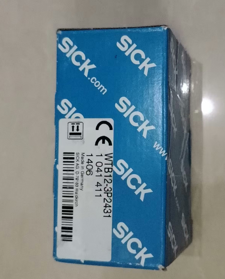
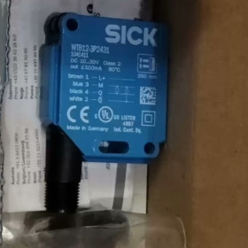
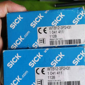
Original Order Code: 1041411
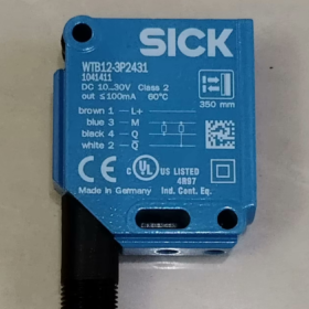
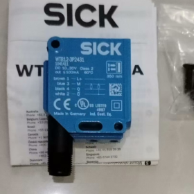
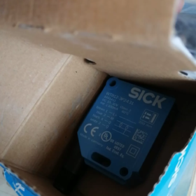
Corresponding Model: WTB12-3P2431
Product Series: W12-3 Industrial Photoelectric Sensor Series
Product Type: Diffuse Photoelectric Sensor with Background Suppression (BGS)
Model Code Breakdown
| Code | Description |
| WT | Diffuse photoelectric sensor (general prefix for W series) |
| B | Built-in Background Suppression (BGS), eliminates interference from rear background |
| 12 | W12 standard square industrial housing series |
| -3 | 3rd-generation upgraded platform equipped with SIRIC intelligent optical chip |
| P | PNP output (sourcing output) |
| 2431 | Function code: 350 mm sensing range, M12 4-pin connector, potentiometer adjustment, light-on/dark-on switchable |
- Core Technical Specifications
| Item | Specification |
| Sensing Principle | Diffuse photoelectric sensor (Background Suppression type) |
| Light Source | Visible red LED, wavelength: 640 nm |
| Standard Sensing Range | 20 mm ~ 350 mm (based on standard white card with 90% reflectivity) |
| Supply Voltage | DC 10 V ~ 30 V |
| Output Type | Single-channel PNP digital output, light-on / dark-on selectable |
| Max Output Current | 100 mA |
| Response Time | ≤ 0.33 ms |
| Switching Frequency | Max. 1500 Hz |
| Adjustment Mode | 5-turn potentiometer for threshold setting |
| Connection Type | M12 4-pin male connector |
| Housing Material | Metal body + PMMA optical lens |
| Protection Class | IP66 / IP67 / IP69K |
| Operating Temperature | -40 ℃ ~ +60 ℃ |
| Dimensions (W × H × D) | 15.6 mm × 48.5 mm × 42 mm |
| Weight | Approx. 120 g |
| Certifications | CE, RoHS |
- Application Environment
Recommended Applications
- Automotive Manufacturing: Presence detection and type identification of seat frames and stamped parts; resistant to interference from metallic tooling backgrounds.
- Food & Beverage Filling Lines: Position detection of bottles and packaging boxes. IP69K rating withstands high-pressure hot water washing and sanitization.
- Packaging Machinery: Product positioning and label detection, unaffected by discoloration or wear on conveyor belts.
- Logistics Sorting: Presence and posture detection of parcels, free from interference from wall or conveyor backgrounds.
- 3C Electronic Production Lines: Feeding position detection for PCBs and small components; reliable detection of dark-colored workpieces.
Not Recommended Applications
- Detection of fully transparent objects such as ultra-thin transparent glass and films (no dedicated algorithm for transparent object detection).
- Long-distance detection beyond 350 mm.
- Extreme corrosive environments with prolonged exposure to corrosive gas or liquid.
- Areas with high voltage and strong electromagnetic interference (no enhanced EMC shielding).
- Full Series List (W12-3 Background Suppression Diffuse Series)
| Order Code | Model | Output Type | Sensing Range | Connection |
| 1041411 | WTB12-3P2431 | PNP | 20~350mm | M12 4-pin connector |
| 1041412 | WTB12-3N2431 | NPN | 20~350mm | M12 4-pin connector |
| 1041409 | WTB12-3P2411 | PNP | 20~350mm | 2m fixed cable |
| 1041410 | WTB12-3N2411 | NPN | 20~350mm | 2m fixed cable |
| 1041404 | WTF12-3P2431 | PNP | 30~175mm (Foreground Suppression) | M12 4-pin connector |
| 1041408 | WTF12-3N2431 | NPN | 30~175mm (Foreground Suppression) | M12 4-pin connector |
- Cross-Brand Replacement List
Original Manufacturer Replacement
Models with identical specifications in the same series are fully interchangeable mechanically and electrically. For example, WTB12-3P2411 (cable type) can replace the connector version, with only different wiring methods.
Equivalent International Brands
| Brand | Equivalent Model | Matching Rate | Remarks |
| Omron | E3Z-LS63 | 95% | PNP, background suppression, 300 mm range, M12 connector, slightly smaller size |
| Pepperl+Fuchs (P+F) | OBT350-R100-2EP-IO-V31 | 92% | 350 mm range, PNP, with IO-Link, richer functions |
| Schneider Electric | XUM9APSBM8 | 90% | Same range, PNP output, M12 connector, compatible mounting holes |
Domestic Compatible Replacements
Hugong E3Z-D63 (PNP): Compatible basic detection functions and similar mounting dimensions. Cost is approx. 1/3 of the original model, ideal for cost-sensitive general applications.
Xinje PSB350-MNDT: Background suppression type, PNP output, 350 mm range. Cost-effective domestic industrial solution.
- Common Faults & Troubleshooting Procedures
- No output and indicator light off
Check if supply voltage is within DC 10~30 V; verify wiring polarity (Brown = Positive, Blue = Negative); inspect M12 pins for oxidation or looseness; check cables for open circuits.
- Failure to detect objects, no trigger signal
Confirm the target is within the effective sensing range; turn the potentiometer clockwise to increase sensitivity; clean dust and oil on the optical lens; check reflectivity of the target (effective range decreases for dark or light-absorbing objects).
- False triggering, output signal without target
Adjust mounting angle to avoid highly reflective backgrounds; shield intense ambient light (sunlight, high-power lamps); keep sufficient spacing between multiple sensors to prevent optical crosstalk; turn the potentiometer counterclockwise to reduce sensitivity.
- Actual sensing range shorter than rated value
Wipe dirt off the lens; recalibrate the potentiometer for maximum range; note that dark and matte objects will reduce the effective sensing distance.
- Typical Application Cases
- Position Detection of Automotive Seat Base Components
Installed on rotary workstations of automotive assembly lines to verify proper assembly of seat frame parts. Background suppression eliminates interference from metallic rotary fixtures, ensuring stable detection of stamped parts in black, grey and metallic finishes. Long-term false detection rate is lower than 0.01%.
- Bottle Detection for Beverage Filling Lines
Mounted at the end of bottled beverage lines to detect PET bottles for inkjet marking. IP69K protection withstands regular high-pressure hot water cleaning. Background suppression is immune to color wear and fading on conveyors, supporting the maximum 1500 Hz switching frequency for high-speed production.
- Component Reel Detection for SMT Lines
Used on rack stations of electronic assembly lines to check installation of component reels. Accurately detects small plastic reels and blocks interference from metal rack backplates. Compact size suits densely arranged production layouts.
Supplementary Notes
This model is a mass-production standard product of SICK with no obsolescence notice. Regular stock is available via standard distributors for procurement and technical support.
Troubleshooting Manual for SICK W12-3 Series Diffuse Photoelectric Sensors
The SICK W12-3 series includes three sub-types: WT (Standard Diffuse), WTB (Background Suppression) and WTF (Foreground Suppression). Adopting the 3rd-generation SIRIC intelligent optical chip, it features IP66/IP67/IP69K high protection. Its faults follow general rules for photoelectric sensors while having series-specific causes. Below is classified troubleshooting covering over 95% of on-site abnormal conditions.
- Power & Wiring Faults (No Response at All)
Symptom
Power indicator off, no signal output, sensor completely out of operation.
Root Causes
- Reversed wiring polarity or mismatched M12 pin definition
- Supply voltage out of DC 10~30 V rated range (undervoltage / overvoltage)
- Broken internal cable, loose or oxidized connector pins leading to poor contact
- Short-circuited output triggering built-in overcurrent protection and latch-up
Troubleshooting Steps
- Confirm wiring standard: Brown = DC Positive, Blue = DC Negative, Black = Signal Output. M12 4-pin definition: Pin 1 = Positive, Pin 3 = Negative, Pin 4 = Output, Pin 2 = Spare.
- Measure supply voltage with a multimeter to eliminate undervoltage/overvoltage caused by line voltage drop or power supply failure.
- Check loose or corroded M12 connectors. Replace with a spare cable to rule out intermittent open circuits.
- In case of output short circuit, disconnect the load and restart power. The self-recovering overcurrent protection generally will not cause permanent damage.
- Detection Failure (No Output with Target Present)
Symptom
No signal output and no indicator change when the target passes the sensing area.
Root Causes
- Target beyond effective range or with extremely low reflectivity
- Potentiometer threshold set too low
- Dust, oil or condensation on optical lens blocking light path
- Excessive mounting angle deviation; reflected light fails to reach receiver
- Exclusive for WTB (Background Suppression): Too small distance between target and background, which is filtered out by algorithm
Troubleshooting Steps
- Verify range matching: Rated range is based on 90% reflectivity white card. Effective distance decreases by 30%~50% for black, matte or curved objects; reserve sufficient margin.
- Clean the lens gently with lint-free cloth and anhydrous alcohol to remove dust, oil and condensation — the most common on-site cause.
- Turn the sensitivity potentiometer clockwise gradually until stable triggering is achieved.
- Adjust mounting angle to keep the optical axis perpendicular to the target surface and avoid reflected light deviation caused by oblique incidence.
- For WTB models: If the target is close to the background, recalibrate the potentiometer and ensure the distance between target and background is ≥ 20 mm for reliable distinction.
- False Triggering & Abnormal Operation (Output without Target)
Symptom
Unintended output when no target exists, or unstable flickering signals during detection.
Root Causes
- Intense ambient light interference: Direct sunlight or high-power halogen/LED lights shining on the receiver
- High-reflective background objects (metal fixtures, mirror belts, white walls) misread as targets
- Optical crosstalk between multiple sensors installed side by side
- Excessively high sensitivity detecting airborne dust, lint or mist
- Severe electromagnetic interference near inverters, servo motors or parallel layout of power cables and signal cables
- Loose mounting bracket causing optical axis offset due to vibration
Troubleshooting Steps
- Block direct strong light or adjust installation angle away from incident light.
- Replace standard diffuse sensors with WTB background suppression models if troubled by background interference. For WTB units, slightly turn the potentiometer counterclockwise to narrow sensing range and shield high-reflective backgrounds.
- Maintain horizontal spacing ≥ 50 mm between adjacent sensors or stagger optical axes to avoid mutual irradiation.
- Lower sensitivity appropriately to eliminate false triggers from fine particles and mist.
- Use shielded cables with single-point grounding in high-EMI environments. Separate signal cables and power cables into different conduits with spacing ≥ 20 cm.
- Fasten brackets and screws to eliminate vibration.
- Unstable Performance (Intermittent Operation)
Symptom
Same target is detected intermittently; sensing distance fluctuates randomly.
Root Causes
- Periodic dust/condensation on lens leading to variable light transmittance
- Excessive power supply ripple or poor contact causing unstable voltage
- Partially broken cable conductors with intermittent open circuit under bending or vibration
- Parameter drift of optical components due to sharp temperature changes
- Unfixed posture or orientation of targets leading to fluctuating reflected light intensity
Troubleshooting Steps
- Increase lens cleaning frequency in high-humidity and dusty environments; install dust covers if necessary.
- Measure power ripple to ensure stable power supply. Add filter power supplies for extreme working conditions to suppress surge.
- Replace with spare cables to exclude intermittent circuit and connector faults.
- Reserve over 20% extra sensing range under extreme high/low temperature to offset component drift.
- Optimize tooling positioning to keep consistent posture and orientation of passing targets.
- Hardware Damage & Aging Faults
Symptom
Function cannot be restored after conventional troubleshooting, indicating permanent hardware failure.
Root Causes
- Cracked, scratched lens or damaged coating leading to light path failure
- Failed housing seal; water/dust ingress causing internal PCB corrosion
- Worn potentiometer from frequent adjustment with no response
- Internal circuit breakdown caused by overvoltage or surge (mostly from lightning strike or power failure)
- LED light source aging and power attenuation under long-term high temperature, resulting in reduced sensing distance
Troubleshooting Steps
- Visual inspection: Check lens cracks, housing fractures and seal failure. Note that IP69K protection is only valid for intact housings. Protection performance fails immediately once the lens is damaged.
- Replace the whole sensor if the potentiometer has no response throughout adjustment travel.
- Replace the sensor directly if power is normal but indicator stays off (internal circuit breakdown, non-repairable).
- Replace the sensor if the actual sensing distance remains below 70% of rated value after lens cleaning (light source aging).
On-site Quick Diagnosis (5-Step Troubleshooting Method)
- Check Power: Measure voltage, verify wiring and check power indicator
- Visual Inspection: Clean lens, check mounting tightness and housing integrity
- Adjust Threshold: Turn potentiometer from low to high and test triggering performance
- Eliminate Interference: Block strong light, isolate background and test with independent power supply
- Replacement Test: Swap with a confirmed good unit to distinguish between sensor failure and peripheral system faults


")


NH42-63-318x560.png "CHINT PC-type automatic transfer switches (ATS)NH42-63/4SZ")


