 Contactor,circuit breaker,solar inverter,electric meter,solar batteries

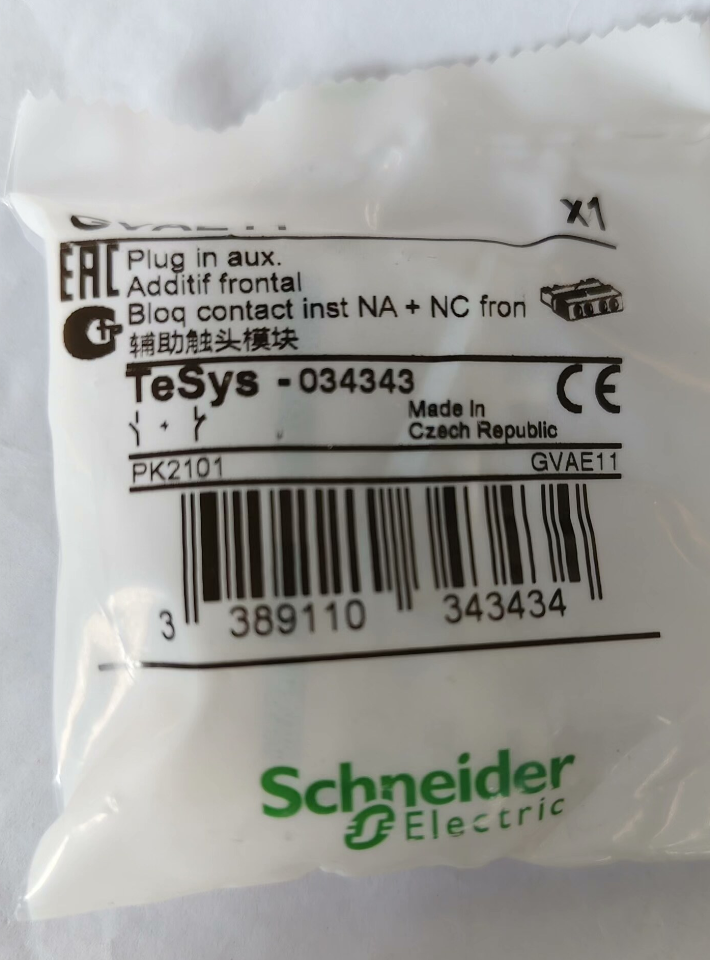


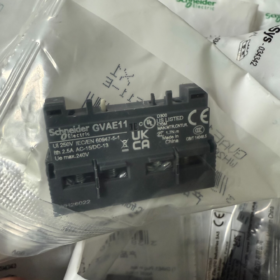
GVAE11 is a 1NO + 1NC instantaneous auxiliary contact block of Schneider TeSys GV series. It is front-mounted and compatible with GV2/GV3 series motor circuit breakers. With a rated current of 2.5A and IP20 protection degree, it is used for status monitoring and signal feedback of motor control circuits, serving as a standard accessory for motor control in industrial automation systems.
| Code Segment | Meaning | Description |
| GVA | Product Category | Auxiliary contact block for GV series |
| E | Mounting Position | Front mounting, different from side-mounted models |
| 11 | Contact Configuration | 1 Normally Open (NO) + 1 Normally Closed (NC) instantaneous contacts with mechanical linkage |
Full Model Definition: GVAE11 = Schneider GV series, front-mounted, 1NO+1NC instantaneous auxiliary contact block
- Core Technical Specifications
| Category | Specifications | Remarks |
| General Characteristics | ||
| Product Type | Instantaneous auxiliary contact block | Mechanically linked, operates synchronously with main contacts of circuit breaker |
| Contact Configuration | 1NO + 1NC (Instantaneous) | NO/NC status switches in sync with the main circuit of the circuit breaker |
| Compatible Devices | Schneider TeSys GV2/GV3 series motor circuit breakers | Compatible with GV2L, GV2LE, GV2ME, GV2P, GV2RT, GV3L, GV3P and other models |
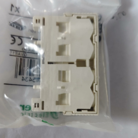
| Mounting Method | Front snap-on installation | Tool-free assembly & quick removal with precise positioning |
| Electrical Parameters | ||
| Rated Operational Voltage | 24–240V AC, 24–60V DC | Suitable for standard voltages of control circuits |
| Rated Operational Current | 2.5A (Ith) | Continuous current carrying capacity |
| Rated Insulation Voltage | 690V AC | Complies with insulation requirements for industrial control circuits |
| Mechanical Endurance | 100,000 operating cycles | High reliability for frequent operations |
| Electrical Endurance | 100,000 operating cycles (AC-15 2.5A/240V) | Meets long-term service requirements of control circuits |
| Terminal Type | Screw terminals | Copper wire cross-section: 0.5–1.5mm²; Tightening torque: 0.8–1.2Nm |
| Physical & Environmental Parameters | ||
| Protection Degree | IP20 | Prevents finger access to live parts |
| Dimensions (W × H × D) | 45 × 20 × 15mm | Compact structure, no extra installation space required for circuit breakers |
| Operating Temperature | -25℃ ~ +60℃ | Wide temperature range for industrial environments |
| Color | Grey | Matches the appearance of GV series circuit breakers |
| Certifications | CCC, UL, CSA, EAC | Multi-standard certifications for global application |
| Ordering Information | ||
| Manufacturer Part No. | GVAE11 | Official Schneider model |
| Standard Order Code | GVAE11 | Original imported version |
| EAN Code | 3.38911E+12 | International universal commodity code |
- Full Model List (GVAE Series Auxiliary Contacts)
| Model | Contact Configuration | Mounting Position | Compatible Devices | Main Application |
| GVAE1 | 1NO or 1NC (Optional) | Front | GV2/GV3 Series | Simple status indication, single signal output |
| GVAE11 | 1NO + 1NC | Front | GV2/GV3 Series | Standard status monitoring, output open/close signals simultaneously |
| GVAE20 | 2NO | Front | GV2/GV3 Series | Control circuits requiring multiple NO signals |
| GVAE02 | 2NC | Front | GV2/GV3 Series | Control circuits requiring multiple NC signals |
| GVAE14 | 1NO + 1NC | Side | GV2/GV3 Series | Side mounting for space-limited installations |
| GVAE24 | 2NO | Side | GV2/GV3 Series | Side mounting for multiple NO signal demands |
| GVAE04 | 2NC | Side | GV2/GV3 Series | Side mounting for multiple NC signal demands |
- Replacement Models & Competitor Comparison
4.1 Internal Schneider Replacements
| Original Model | Replacement Model | Differences | Application Scenarios |
| GVAE11 | GVAE14 | Different mounting position (side mounting) | Insufficient front space, side mounting required |
| GVAE11 | GV2ME + Built-in Contacts | Integrated design, no extra assembly needed | New equipment selection for integrated layout |
| GVAE11 | GV3P + Built-in Contacts | Upgraded series with enhanced functions | High-standard applications requiring advanced protection |
4.2 Cross-brand Competitor Comparison
| Brand | Model | Contact Configuration | Compatible Devices | Main Differences |
| Schneider | GVAE11 | 1NO + 1NC | GV2/GV3 Series | Precise mechanical linkage, IP20 protection, high compatibility |
| ABB | MS132-01 | 1NO + 1NC | MS132 Series | Side mounting, rated current 3A, similar price |
| Siemens | 3RV2091-1A | 1NO + 1NC | 3RV20 Series | Plug-in mounting, rated current 2A, complete certifications |
| Eaton | PKZM0-AUX11 | 1NO + 1NC | PKZM0 Series | Front mounting, rated current 2.5A, spring terminals |
| Chint | NXC-A11 | 1NO + 1NC | NXC Series | Cost-effective, reliable domestic alternative |
- Application Environments & Typical Cases
5.1 Recommended Applications
Motor Control Circuit: Feedback circuit breaker ON/OFF status for PLC/DCS system monitoring
Alarm System: Trigger audible and visual alarms via NC contacts when the circuit breaker trips
Interlock Control: Prevent simultaneous startup of multiple motors and realize sequence control
Remote Monitoring: Transmit status signals to SCADA system for remote diagnosis
Safety Circuit: Form safety protection circuits together with emergency stop buttons
5.2 Not Recommended Applications
Main Circuit Usage: Rated current is only 2.5A, not applicable for motor main circuits
High-frequency Switching: Over 1000 switching cycles per hour will shorten service life
Severe Electromagnetic Interference Environment: Additional shielding is required to avoid malfunction
Humid/Corrosive Environment: IP20 protection is insufficient; install extra enclosure or select higher protection grade products
5.3 Typical Application Cases
Case 1: Pump Unit Control in Wastewater Treatment Plant
Equipment: 15kW submersible pump, GV2P32 circuit breaker + GVAE11 auxiliary contact
Configuration: NO contact of GVAE11 connected to PLC digital input module; NC contact connected to alarm circuit
Outcome: Real-time monitoring of pump operating status, automatic alarm and event recording upon faults
Case 2: Conveyor System in Automotive Production Line
Equipment: 12 conveyor lines, each equipped with GV2P32 + GVAE11
Configuration: GVAE11 contacts linked with PLC to realize sequential startup and interlock protection for conveyors
Features: Mechanical linkage ensures accurate status feedback and reduces misjudgment of control systems
- Troubleshooting & Maintenance Manual
6.1 Common Faults & Solutions
| Fault Phenomenon | Possible Causes | Solutions |
| No change of contact signals | 1. Improper installation of contact block | 1. Reinstall the block and ensure the clip is fully engaged |
| 2. Damaged mechanical linkage | 2. Inspect linkage mechanism and replace damaged unit | |
| 3. Burned or oxidized contacts | 3. Clean or replace the contact block | |
| 4. Wrong wiring | 4. Check wiring and confirm correct connection of NO/NC contacts | |
| Contact welding | 1. Excessive current in control circuit | 1. Ensure control circuit current ≤ 2.5A |
| 2. Overheating caused by frequent switching | 2. Reduce switching frequency or select higher-rated contacts | |
| 3. Arc erosion | 3. Replace with a new contact block | |
| Signal interference | 1. Control wires not separated from main wires | 1. Separate control wires from main wires (spacing ≥ 100mm) |
| 2. No shielded cable used | 2. Use shielded cable with single-end grounding | |
| 3. Poor grounding | 3. Inspect and ensure reliable grounding | |
| Loose installation | 1. Clip not fully locked | 1. Reinstall until a click sound is heard |
| 2. Loosening caused by vibration | 2. Fit shock-absorbing pads or reinforce installation |
6.2 Maintenance Procedures
- Daily Inspection (Weekly)
Check installation condition and ensure no looseness
Inspect terminals for overheating and looseness
Test contact switching to confirm synchronization with circuit breaker
- Routine Maintenance (Every 6 Months)
Power off and remove dust on the contact block
Measure contact resistance (shall be ≤ 50mΩ)
Check flexibility of mechanical linkage
- Annual Maintenance
Replace frequently used contact blocks
Test insulation performance of control circuits
Retighten all electrical connections
6.3 Quick Diagnosis Tips
No signal? Check installation and linkage first.
Contact welded? Limit current and cut switching times.
Signal interference? Separate wires, apply shielding and good grounding.
Loose fitting? Re-clip firmly and add shockproof measures for vibrating sites.
- Selection & Installation Guidelines
7.1 Selection Rules
Compatibility: Confirm matching with GV2/GV3 series circuit breakers; not applicable for other series
Contact Configuration: Select 1NO+1NC (GVAE11), 2NO (GVAE20) or 2NC (GVAE02) according to control demands
Mounting Position: Choose GVAE11 for front mounting, GVAE14 for side mounting
Current Matching: Control circuit current shall not exceed 2.5A; select higher-specification products if overloaded
7.2 Installation Notes
Installation Sequence: Install circuit breaker first, then attach the contact block and fully lock the clip
Wiring Standard: Use 0.5–1.5mm² copper wires with tightening torque of 0.8–1.2Nm; avoid over-tightening
Clear Marking: Label NO/NC contacts to prevent wiring errors
Linkage Test: Manually operate the circuit breaker after installation to verify synchronous contact action
Protection Measures: Install extra enclosures for dusty or humid environments
- Production Status & Replacement Solutions
Current Status of GVAE11: In production, no discontinuation plan (as of June 2026)
Upgrade & Replacement Options:
- Functional Upgrade: GV3 series models with built-in contacts (no extra assembly, fewer fault points)
- Intelligent Upgrade: TeSys T series (with communication function for network-based status transmission)
- Domestic Alternative: Compatible domestic GVAE11 models (lower cost with equivalent performance)


 Sensor")


")


NH42-63-318x560.png "CHINT PC-type automatic transfer switches (ATS)NH42-63/4SZ")


