 Contactor,circuit breaker,sensor,Encoder,PLC,Converter

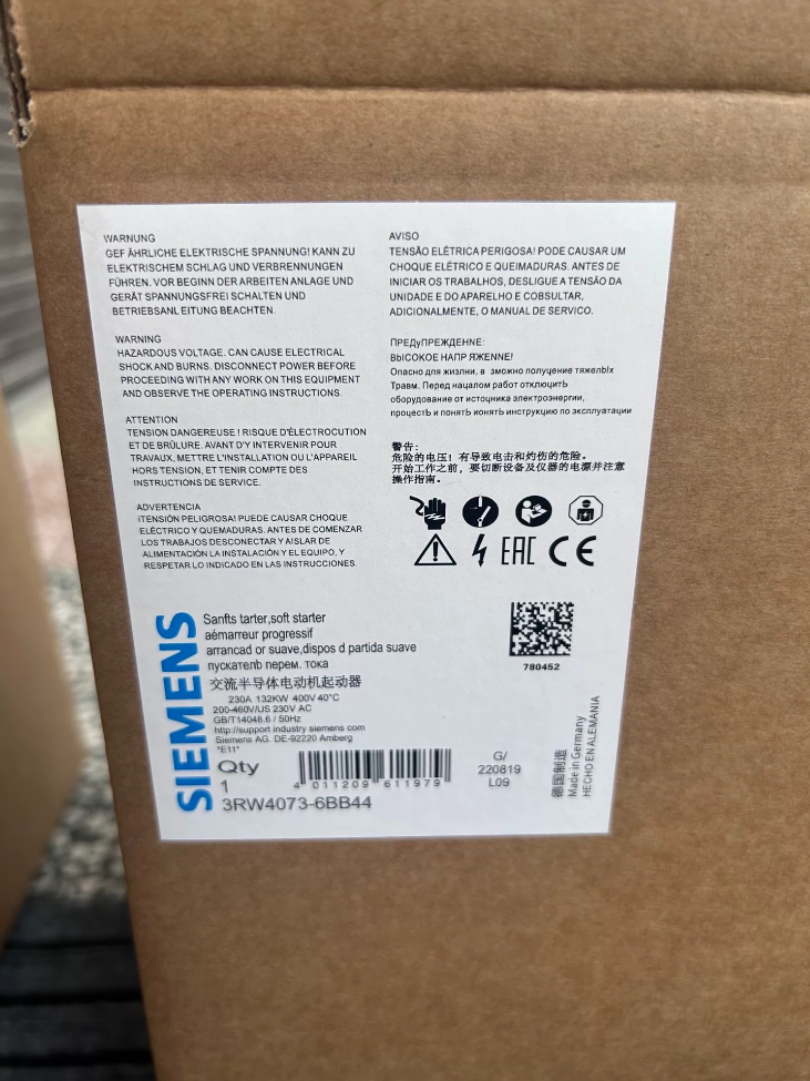

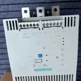
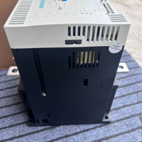
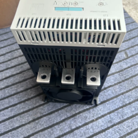
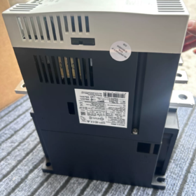
SIRIUS 3RW40 Standard Soft-Starter, Discontinued, Integrated Bypass Contactor, Frame Size S12
- Model Decoding
3RW: Soft-Starter series;40: Standard series;74: Frame S12, rated current 280 A
6: Screw terminals (main circuit bus-bar connection)
BB: Control supply AC 230 V
4: Main circuit voltage 200-460 V AC; Last digit 4: Standard version
- Key Electrical Specifications
| Item | Specifications |
| Main circuit operating voltage | 200‑460 V AC, 50/60 Hz |
| Rated operational current Ie @40 ℃ | 280 A |
| Rated motor power @400 V | 160 kW (standard connection) |
| Control supply voltage | AC 230 V |
| Integrated bypass contactor | ✅ Built‑in; bypass thyristors after start‑up to reduce heat generation |
| Protection class | IP20, cabinet‑mount installation |
| Trip class | Class10 / 15 / 20 adjustable, built‑in motor overload protection |
| Starting current limit | 1.5‑5 × Ie adjustable |
| Soft‑start ramp time | 0‑20 s;Soft‑stop time 0‑20 s |
| Ambient temperature | ‑25~+60 ℃ |
| Dimensions Frame S12 | W270 × H470 × D278 mm |
- Terminals & Functional Highlights
- Start command: Short terminals 1-3 for start, open for stop; terminal 2-3 accepts DC24V control signal
- Auxiliary relay contacts:
13-14: Run status output
23-24: Stop status output
95-96-98: Fault alarm contact
- Supports motor PTC thermistor protection input
- Front-panel potentiometer setting: current limit, ramp time, soft-stop, motor rated current; LED status / fault indicators
- Direct Replacement Model (New-generation 3RW5 series)
Factory recommended replacement: 3RW5074-6AB14
Identical rating: 280 A /160 kW@400 V; control supply AC230V; integrated bypass; screw terminals
Functionally compatible, reduced footprint, enhanced diagnostics, drop-in replacement for 3RW4074-6BB44
- Typical Applications
Pumps, fans, compressors, conveyors and other light-to-medium starting loads. Not suitable for heavy-duty frequent starting; select high-performance 3RW55 series for heavy-duty conditions.
- Selection & Protection Notes
- Max. cable length between soft-starter and motor ≤300 m
- Semiconductor protection: 3NH / 3NE series semiconductor fuses (coordination type 2) is recommended
- Derate output for installation altitude > 1000 m
- For retrofit spare-parts: use surplus stock / second-hand units; new projects shall adopt 3RW50 series.
3RW4074-6BB44 (Frame S12) Installation Instructions
DIN-rail mounting NOT supported. Only panel-mount via bolt fixing. IP20 cabinet-mount installation. Unit must be installed vertically to maintain upward-downward cooling airflow.
Mechanical Fixing
- Mounting method: Fasten onto cabinet back-plate by 4 × M8 bolts. No DIN-rail clips available for this large-size S12 frame.
- Overall dimensions: Width 270 mm × Height 470 mm × Depth 278 mm
- Allowable mounting inclination (without external fan):
Max. tilt ±10° relative to vertical back-plate. Never lay flat or invert unit, otherwise thermal trip will occur due to deteriorated cooling.
- Required ventilation clearances (side-by-side installation must comply strictly):
Top clearance ≥ 100 mm (critical for hot-air exhaust)
Bottom clearance ≥ 75 mm (cool-air intake)
Lateral clearance ≥ 5 mm
If multiple soft-starters are closely arranged, increase vertical clearances. Install cabinet exhaust fan for high-temperature environments.
Wiring Instructions
- Main circuit L1/L2/L3, T1/T2/T3: Bus-bar bolted connection
Terminals are bus-bar type, suitable for bus-bar or large-size cables (95-300 mm²). Apply torque-wrench to specified torque; retorque after initial operation to prevent overheating at terminals.
Input: L1-L2-L3; Output to motor: T1-T2-T3. Do NOT reverse input and output connections.
- Control-circuit screw terminals:
A1-A2: Control supply AC 230 V; start command, PTC input and auxiliary relay contacts use screw terminals.
- Protective earth PE: Connect protective-earth bolt on device housing. Do NOT rely only on bus-bar for earthing continuity.
Environmental Conditions
Install inside electrical cabinet only (IP20 rating). Avoid dust, corrosive gas.
Ambient temperature: -25 ℃~+60 ℃; derate output above 40 ℃.
Derate output for altitude > 1000 m; maximum permissible installation altitude 5000 m. Voltage rating is further reduced above 2000 m.
Max. motor cable length 300 m. Output reactor required for longer cables.
Installation Prohibitions
- ❌ Horizontal / flat / inverted mounting is forbidden, airflow loss causes thermal faults.
- ❌ DIN-rail mounting not possible (no DIN-rail accessories for S12 frame).
- ❌ Do not mount heat-generating components (contactors, circuit-breakers) directly above soft-starter.
- ✅ Ensure natural cabinet air convection; forced ventilation recommended for frequent-start applications.
Installation differences for replacement model 3RW5074-6AB14
New-generation 3RW5074-6AB14 (160 kW) is also S12 frame, bolt-on panel-mount. Required ventilation clearances are same as 3RW4074-6BB44. Mounting hole pattern is compatible for direct field replacement.
Common Faults of 3RW4074-6BB44 (S12 / 160 kW)
This unit has no numerical fault codes. Diagnostics rely on three front-panel LEDs: DEVICE power, STATE/BYPASS status, OVERLOAD overload. Fault relay terminals 95-96-98 provide remote fault signalling.
Integrated bypass contactor, thyristor power modules and thermal cooling path are most frequent failure points for this large-frame unit.
- Device over-temperature trip (DEVICE yellow LED, STATE red LED)
Symptom: Trip during starting, radiator is extremely hot
- Insufficient cabinet ventilation clearance, insufficient top-side space (<100 mm); hot-air recirculation in multi-unit layout; high cabinet ambient temperature; dust-clogged heat-sink fins.
- Mounting tilted / laid-flat, cooling airflow destroyed.
- Too-frequent motor starts (high number of starts per hour).
- Internal bypass contactor fails to close, thyristors continuously carry full load current.
Troubleshooting: Clean heat-sink dust; maintain specified ventilation gaps; reduce start frequency; listen for bypass-contactor closing click; power-off and cool unit ≥30 minutes before reset.
- Phase-loss / No-load fault (STATE/BYPASS red LED)
Symptom: Fault trips immediately after start command is applied
- Loose main-circuit bus-bar terminals (L1/L2/L3); blown semiconductor fuse on one phase.
- Open-circuit motor-side wiring T1/T2/T3; broken motor cable.
- Motor rated current less than 20 % of soft-starter rated current (under-load detection trips when oversized soft-starter drives small motor).
- Defective internal current-transformer, incorrect main-current sampling by control board.
Troubleshooting: Retighten all power bus-bar connections; measure three-phase input & output voltages. Verify motor rated current must not be far below 160 kW.
- Motor overload trip (OVERLOAD red LED ON)
- Excessive mechanical load, jammed pump / fan machinery.
- Front-panel Ie potentiometer mis-adjusted (not set according to motor nameplate current); incorrect overload trip Class setting.
- Motor PTC thermistor protection triggered (terminals T11-T12): motor winding over-temperature.
- Mains supply voltage drop increases starting current.
After electronic thermal overload trip, thermal-model must cool down. Repeated immediate reset attempts will cause re-trip.
- Bypass contactor fails to close (Most common ageing-related fault)
Symptom: STATE/BYPASS LED does not switch to steady-green after completion of soft-start; unit runs continuously hot.
- Soft-start ramp time not completed, bypass condition not satisfied; ramp-time setting excessively long.
- Burned-out bypass-contactor coil; pitted / welded / non-closing contact points (common ageing failure on legacy units).
- Main-control-board no drive signal for bypass contactor.
Risk: Thyristors continuously conduct full operating-current, rapid over-temperature trip or permanent power-module damage.
Troubleshooting: Listen for audible “click” closing sound at end of start ramp. Never permit long-time operation without valid bypass closure; repair or replace bypass contactor assembly.
- No response at power-on, DEVICE LED off
- Missing / incorrect AC 230 V control-supply voltage at terminals A1-A2; loose terminals.
- Blown internal fuse on control-power-supply board, power-supply board failure.
This model requires AC 230 V control supply; DO NOT apply DC 24 V to A1-A2.
- Short-circuit trip immediately upon start command; DEVICE red LED
- Thyristor module short-circuit breakdown (common S12 large-frame failure, caused by surge-voltage, lightning-transient or output short-circuit).
- Phase-to-phase or phase-to-earth short-circuit on motor / power cable.
- Welded-closed contacts on internal bypass contactor.
Troubleshooting: Power-off and wait 5 minutes for circuit discharge before cabinet access. Measure thyristor anode-cathode resistance with multimeter. Thyristor failure normally requires replacement of power-section assembly.
- False PTC thermistor fault alarm
Symptom: Fault alarm occurs even before start-up.
Loose PTC wiring terminals; damaged motor thermistor.
If PTC sensor is not used, terminals T11-T12 must be short-circuited, otherwise external-sensor fault will trigger.
- Motor fails to rotate upon start command
- Initial starting-voltage set too low; current-limit setting too restrictive for load torque.
- Soft-start ramp-time set too short.
- Mechanical load seized / jammed.
- One-phase loose / high-resistance joint on main-circuit bus-bar.
Important On-Site Servicing Precautions
- After de-energising main power circuit: Wait minimum 5 minutes for residual-voltage discharge before opening cabinet covers, to avoid residual-voltage shock hazard.
- All main-circuit bus-bar bolt torques must be applied with torque-wrench; retorque after initial operating period to prevent terminal overheating.
- For second-hand / surplus-stock units: critical inspection points include bypass-contactor contact condition, thyristor module integrity, and heat-sink dust accumulation.
Fault-Indication Table for Siemens 3RW4074-6BB44
⚠️ This unit has no numerical fault-codes; diagnostics are performed via three front-panel LED indicators
Front-panel LED labels:
- DEVICE (Device Power)
- STATE/BYPASS (Status / Bypass)
- OVERLOAD (Overload)
Fault-relay terminals: 95-96-98. Relay contacts toggle for any fault event. Reset button: RESET/TEST.
| DEVICE | STATE/BYPASS | OVERLOAD | Fault Description | Troubleshooting Action |
| Off | Off | Off | No control‑supply voltage | Check AC 230 V supply at A1‑A2; inspect control‑circuit fuse |
| Green steady | Green flashing | Off | Normal soft‑start in progress | Ramp‑up phase, normal operating state |
| Green steady | Green steady | Off | Normal bypass running | Start‑up complete, bypass‑contactor closed, normal operation |
| Green steady | Red steady | Off | Phase loss / No‑load detected | 1. Blown fuse / loose main‑circuit connections; 2. Bus‑bar terminal loosening; 3. Motor current too low; 4. Current‑transformer fault. Retighten L1/L2/L3 and T1/T2/T3 bus‑bar connections. |
| Green steady | Off | Red steady | Motor thermal overload trip | Motor over‑load / mechanical jam; incorrect Ie potentiometer setting; thermal‑model protection. Allow sufficient cooling time before reset; avoid frequent reset attempts. |
| Green steady | Off | Red fast‑flash | PTC thermistor fault | Open‑circuit / short‑circuit PTC wiring. Short‑circuit terminals T11‑T12 if motor thermistor input is unused. |
| Yellow steady | Red steady | Off | Soft‑starter internal over‑temperature | Dust‑clogged heat‑sink; insufficient ventilation clearance; excessive start frequency; bypass‑contactor not closing; high cabinet ambient temperature. Power‑off and allow complete cooling; clean heat‑sink assembly. |
| Red steady | Red steady | Any | Severe hardware failure | Thyristor breakdown; welded bypass‑contactor contacts; main‑board damage. Unit requires repair; do not attempt further operation. |
| Green steady | Yellow flashing | Yellow flashing | Parameter‑setting invalid warning | Mismatch between motor Ie setting and selected trip Class. Re‑adjust potentiometers according to motor nameplate data. |
Special Operating Conditions
- STATE/BYPASS LED fails to turn steady-green after soft-start completion
Bypass-contactor has not closed. Thyristors remain energised and will quickly trigger thermal trip. Listen for mechanical closing click sound at ramp completion; verify ramp-time parameter; repair or replace bypass-contactor assembly if contacts are burned.
- Fault-reset operation
Auto-reset mode: Automatic reset after thermal cooling.
Manual-reset mode: Press front-panel RESET/TEST push-button after root-cause elimination.
For thermal-protection trips: reset will not take-effect until internal thermal-model has cooled, even if reset button is pressed repeatedly.
- Fault-relay terminals 95-96-98:
Healthy state: 95-96 closed, 95-98 open.
Any fault condition: 95-96 opens, 95-98 closes, for remote alarm signalling.
Quick Field-Diagnosis Cheat-Sheet
- DEVICE LED Yellow → Soft-starter internal over-heat (heat-sink, bypass-contactor, ventilation clearance)
- STATE LED Red → Main-circuit phase-loss or missing motor-load detection
- OVERLOAD LED Red → Motor overload or PTC thermistor fault
- DEVICE LED Red → Catastrophic power-hardware failure (thyristor / main-control-board)





NH42-63-318x560.png "CHINT PC-type automatic transfer switches (ATS)NH42-63/4SZ")



