 Contactor,circuit breaker,sensor,Encoder,PLC,Converter

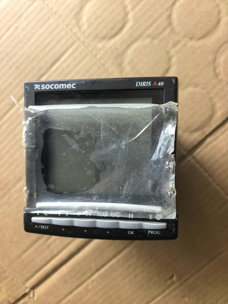

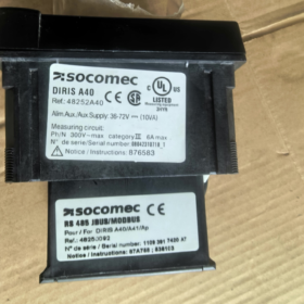
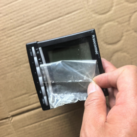
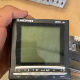
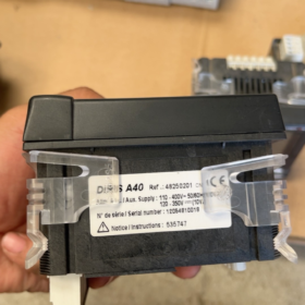
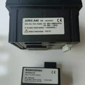
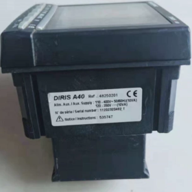
Brand: SOCOMEC
Model Code: DIRIS 48250201
Product Series: DIRIS A40 Multi-function Power Meter
Complete Order Code: 48250201
Core Information
- Full Product Name
DIRIS A40 Multi-function Energy / Power Monitoring Meter
Order Code: 48250201
- Standard Configuration (Model 48250201)
Measurement: Three-phase voltage, current, power, power factor, harmonic, energy metering
Communication: Modbus RS485
Dimension: 96×96mm panel mounting
Power supply: AC/DC 80–270V
Input: Direct voltage input up to 480V; current input requires external CT
Functions: Demand, THD harmonic, event logging, time-of-use energy
Output: Basic version without built-in I/O (Select other variants for relay/pulse output)
- Reference for Distinguishing Similar Models
48250201: DIRIS A40, Modbus, No I/O
48250202: Version with pulse output
48250203: Version with digital input / relay output
Typical Applications
Low-voltage switchgear, busbar cabinets, UPS incoming feeders, data center power distribution, factory energy consumption monitoring; interfacing with SCADA, PLC and energy management systems.
Alternative Options
Original direct replacement: DIRIS A40 series;
Domestic alternatives: Nayu, Yada, Acrel multi-function network power meters (Modbus register compatibility verification required).
Modbus RTU Register Summary for SOCOMEC DIRIS A40 (Order No. 48250201)
Important Prerequisites
- Protocol: Modbus RTU, Function Code 03 (Read Holding Registers). All measurement data are stored in holding registers;
- Data format: 32-bit signed/unsigned integer (occupies two consecutive 16-bit registers, Big-Endian, high word first);
- Address in manual = decimal offset address (PDU address, starts at 0)
For configuration software using 4xxxx format: Offset address + 40001
Example: Offset 786 → Register 40787
- Raw values need scaling division to obtain actual engineering values;
- Two sets of register maps exist: Old map (Firmware ≤2008) / New map (Firmware ≥2009). The table below is the new standard register map used for most field devices.
- Default Communication Parameters
Slave address: 1
Baud rate: 9600
Data bits: 8, Stop bits: 1, Parity: None
Parameters can be modified via front panel menu
- Common Real-Time Measurement Registers (PDU Offset, FC03)
| PDU Offset | Reg Count | Parameter Name | Scaling Factor | Unit | Data Type |
| 786 | 2 | L1-N Voltage U1 | /100 | V | S32 |
| 788 | 2 | L2-N Voltage U2 | /100 | V | S32 |
| 790 | 2 | L3-N Voltage U3 | /100 | V | S32 |
| 792 | 2 | L1-L2 Line Voltage U12 | /100 | V | S32 |
| 794 | 2 | L2-L3 Line Voltage U23 | /100 | V | S32 |
| 796 | 2 | L3-L1 Line Voltage U31 | /100 | V | S32 |
| 798 | 2 | Phase A Current I1 | /100 | A | S32 |
| 800 | 2 | Phase B Current I2 | /100 | A | S32 |
| 802 | 2 | Phase C Current I3 | /100 | A | S32 |
| 804 | 2 | Frequency | /100 | Hz | S32 |
| 806 | 2 | Total Active Power ΣP | /100 | kW | S32 |
| 808 | 2 | Total Reactive Power ΣQ | /100 | kvar | S32 |
| 810 | 2 | Total Apparent Power ΣS | /100 | kVA | S32 |
| 812 | 2 | Total Power Factor PF | /1000 | — | S32 |
| 814 | 2 | L1 Active Power P1 | /100 | kW | S32 |
| 816 | 2 | L2 Active Power P2 | /100 | kW | S32 |
| 818 | 2 | L3 Active Power P3 | /100 | kW | S32 |
- Energy Metering Registers (Energy Counter, 32-bit Unsigned)
| PDU Offset | Reg Count | Parameter Name | Unit | Scaling |
| 860 | 2 | Import Active Energy kWh+ | kWh | Raw value direct use |
| 862 | 2 | Export Active Energy kWh- | kWh | Raw value direct use |
| 864 | 2 | Inductive Reactive Energy kvarh+ | kvarh | Raw value direct use |
| 866 | 2 | Capacitive Reactive Energy kvarh- | kvarh | Raw value direct use |
| 856 | 2 | Operating Hour Counter | h | /100 |
⚠️ Model 48250201 basic version has no pulse output or DI/DO; I/O status registers are not required.
- Reading Example
Read Total Active Power: Offset address 806, read 2 consecutive registers
Returned data [High Word, Low Word] forms a 32-bit integer → Value ÷100 = kW
Example: Raw reading = 12560 → 12560 /100 = 125.60 kW
- Common Pitfalls & Notes
- Word Order: DIRIS A40 uses Big-Endian (high register = high 16-bit). Most configuration software supports this natively; some drivers require manual swap of high/low word.
- Incompatibility between old and new firmware register maps
All readings equal zero: Likely old firmware register map (starts at 0x700).
- CT/PT Ratio: After ratio setting inside the meter, register values already represent primary-side actual values. Do NOT multiply by transformer ratio again.
- Avoid reading excessive continuous registers in one request; limit to ≤20 registers per command to prevent communication errors.
- Extended registers for harmonic, THD, maximum demand and event logs are available and generally unnecessary for conventional data acquisition.
- Access Official Full PDF Document
Official Manual Reference: 536103B (DIRIS A40/A41 Modbus communication manual), containing complete register list, alarm parameters and write registers.
Procedure to Modify RS485 Modbus Communication Parameters via Front Panel for SOCOMEC DIRIS A40 (48250201)
Front Panel Button Definition (96×96 Model)
◀ LEFT: Cursor left / Scroll up
▶ RIGHT: Cursor right / Enter & Confirm
▲ UP: Value increase / Scroll up
▼ DOWN: Value decrease / Scroll down
Default Administrator Password: 100
Default Communication Settings: Slave address=1, Baud rate=9600, Data bits=8, Stop bits=1, Parity=None
Step-by-Step Operation
Step 1: Enter Configuration Menu
Meter displays normal measurement screen (voltage/current view)
- Long press [▶ RIGHT] confirm key for 3~5 seconds
- Screen prompts CODE ?, password input required
Step 2: Input Password 100
▲ UP: Increment digit
▶ RIGHT: Shift cursor to next digit
Set digits sequentially: `1` → `0` → `0`
After input, long press [▶ RIGHT] to enter main configuration menu
Step 3: Navigate to Communication Menu
Scroll using ▲ / ▼ to locate:
RS485 COMMUNICATION
Press ▶ RIGHT to enter submenu
Step 4: Modify Communication Parameters Item by Item
Four configurable items:
- COM ADR (Modbus Slave Address)
Range: 1~247. Ensure unique address for each meter on the bus.
▶ Enter → Adjust value via ▲▼ → ▶ Confirm
- BAUD (Baud Rate)
Options: 1200 / 2400 / 4800 / 9600 / 19200 / 38400 / 57600 /115200
- PARITY
NO: No parity (Recommended for site use)
EVEN: Even parity
ODD: dd parity
- STOP BIT
1 / 2; Standard site setting: 1
⚠️ Critical: Host device (PLC/Gateway/Modbus Poll) parameters must match the meter exactly, otherwise communication failure occurs.
Step 5: Save and Exit
After all parameters modified:
- Scroll to EXIT using ▲▼
- Press ▶ RIGHT to confirm exit
- Prompt SAVE? YES/NO
Select YES to save; select NO to discard all changes.
After successful saving, meter automatically returns to measurement main screen. New communication settings take effect immediately.
⚠️ Common Faults & Reminders
- Forgotten Password 100
Panel modification unavailable. Two solutions:
① Use Easy Config software via RS485 to read or reset password;
② Factory reset (CT ratio, energy data will be cleared. Proceed with caution).
- Troubleshooting checklist if communication fails after parameter modification
No duplicated slave addresses; baud rate, parity and stop bits fully matched
RS485 wiring: A to A, B to B. Do not reverse polarity
120Ω terminating resistor at bus end to be deployed as required
Confirm model 48250201 integrates built-in RS485; no extra communication module required
- Menu Language
Older firmware: English menu `RS485 COMM`
Newer firmware: Chinese menu supported RS485通讯
Recommended Parameter Template
| Parameter | Recommended Setting |
| Slave Address | Assign according to site layout (1~247) |
| Baud Rate | 9600 |
| Parity PARITY | NO (None) |
| Stop Bit STOP | 1 |





NH42-63-318x560.png "CHINT PC-type automatic transfer switches (ATS)NH42-63/4SZ")



