 Contator,disjuntor,sensor,Codificador,CLP,Conversor

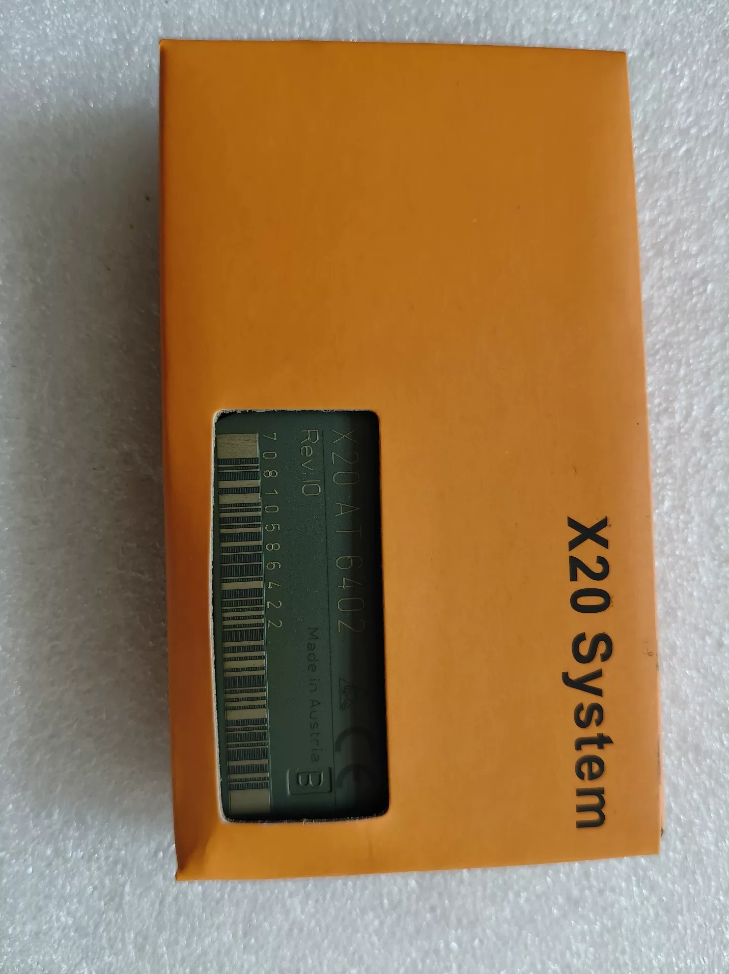

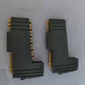
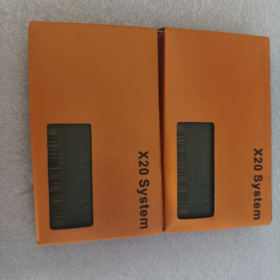
X20: Série de sistemas de E/S X20
NO: Temperatura Analógica entrada
6402: 6módulo termopar de canal; X20cAT6402 é a versão conformalcoated (condensação & corrosivoresistente a gases)
Descrição Geral
X20AT6402 é um módulo de aquisição de temperatura de termopar de 6 canais para E/S distribuída PLC X20. Possui compensação de junção fria terminal integrada, suportando tipos de termopares J/K/N/S/B/R. Sigma Delta 16 bits ADC; ele pode gerar valores de temperatura de engenharia ou leituras brutas de milivolts.
⚠️Nota: Sem isolamento galvânico entre canais; existe isolamento entre o lado do barramento e o lado de E/S.
Acessórios obrigatórios: X20TB12 (12bloco terminal de pinos), Base de ônibus X20BM11. Os terminais NÃO são fornecidos com o módulo.
Principais especificações técnicas
| Item | Especificação |
| Canais | 6 entradas de termopar |
| Termopares suportados | J., K, N, S, B, R (EN60584) |
| ADC | Sigma‑Delta, 16-pedaço |
| Compensação de junta fria | Compensação integrada baseada em terminal; não é necessário PT1000 externo |
| Tempo de filtro | Configurável: 1 ms ~ 66,7 ms |
| Faixa de entrada | ±70mV (sinal mV do termopar) |
| Resolução | 0.1 ℃ / 0.01 ℃ selecionável por software; valor bruto:1.0625 μV |
| Precisão básica @25℃ | J.: ±0,10%; K/N: ±0,11%; S: ±0,17% |
| Tensão de modo comum | ±15V |
| Consumo de energia | Ônibus: 0.01 C; Lado de E/S: 0.91 C |
| Temperatura operacional | Montagem horizontal:0-55°C; Montagem vertical:0-50°C; desclassificar 0,5℃/100m acima de 2.000m de altitude |
| Classe de proteção | IP20, apenas para montagem em gabinete |
| Temperatura de armazenamento | -40 ~ +85℃ |
| Diagnóstico | Status do módulo, detecção de quebra de fio de canal, Indicadores de status LED |
| Formato de saída | INT; temperatura de engenharia ou valores brutos de mV selecionáveis |
Notas de fiação
- Cada canal de termopar usa 2 terminais (CT+, TC). Seis canais ocupam 12 alfinetes, bloco terminal X20TB12 correspondente.
- Não inverta a polaridade do termopar; sempre use fios de extensão de termopar correspondentes.
- Sem isolamento galvânico entre canais. Para medição multiponto, controle a diferença de potencial de referência para evitar interferência de modo comum.
- A compensação Coldjunction usa medição de temperatura terminal integrada; mantenha o bloco terminal longe de componentes geradores de calor.
Configuração de Software (Estúdio de Automação)
- Adicione hardware `X20AT6402` na árvore de hardware.
- Definir tipo de sensor de forma independente (J/K/N/S/B/R) para cada canal.
- Configurar tempo de filtro; selecione a saída: temperatura de engenharia ℃ ou valor bruto de milivolts.
- Habilitar diagnóstico de quebra de fio.
Seleção alternativa da série X20
| Modelo | Canais | Características |
| X20AT2402 | 2 | Módulo termopar econômico de 2 canais, mesmo suporte de sensor |
| X20ATA492 | 2 | Isolamento galvânico canal a canal, requer sensor de junta fria PT1000 externo nos terminais |
| X20cAT6402 | 6 | Revestido conformal; para alta umidade / ambientes de gabinete de gás corrosivo |
Aplicação Típica
Fornos de tratamento térmico, fornos, máquinas de moldagem por injeção, extrusoras, fornos, aquisição de temperatura multiponto para equipamentos relacionados a energia.
Lista de verificação de inspeção de módulos usados
- Verificação visual: Sem marcas de queimadura terminal; contatos dourados do backplane intactos.
- Teste de inicialização: LED DE FUNCIONAMENTO normal; sem alarmes de falha do módulo.
- Teste funcional: Conecte o termopar tipo K conhecido; compare as leituras com o termômetro de referência em todos os canais.
- Verifique a revisão do hardware; distinguir a versão padrão da variante `c` conformalcoated.
B&R Manual de instalação do X20AT6402 (Versão prática em inglês)
Documento oficial completo: Manual do usuário do sistema X20, capítulo 9.32.7 para X20AT6402. Baixar de B&Site oficial R após login. X20cAT6402 compartilha mecânica de hardware idêntica com revestimento isolante aplicado.
Este é o slicestyle X20 I/O. Partes obrigatórias: Base de ônibus X20BM11 + Bloco terminal de mola X20TB12; terminais não estão incluídos no módulo.
1 Pré-condições de segurança
- Instale apenas dentro do quadro elétrico; classificação de proteção IP20. Não para implantação externa.
- Desconecte a alimentação de 24 Vcc para instalação / remoção / fiação. Hotswap é suportado, mas execute a fiação com a energia removida.
- Proteção ESD: Use pulseira antiestática. Não toque diretamente nos contatos do backplane folheados a ouro com a mão.
- Condições ambientais
| Item | Parâmetro |
| Temperatura operacional (montagem horizontal) | 0~+55℃ |
| Temperatura operacional (montagem vertical) | 0~+50℃ |
| Altitude | 0-2.000 m sem restrições; >2000 eu, reduzir a temperatura ambiente em 0,5 ℃ por 100 m de elevação |
| Umidade relativa | 5-95%, sem condensação |
| Armazenar / temperatura de transporte | -40~+85℃ |
2 Instalação Mecânica (Trilho DIN TS35 EN60715)
2.1 Folga obrigatória para dissipação de calor
Folga mínima de 10 mm à esquerda e à direita de cada módulo.
Montagem horizontal: ≥35mm de espaço de ventilação livre acima e abaixo do módulo.
Montagem vertical: A CPU deve ser colocada abaixo de todos os módulos de E/S.
O ângulo de inclinação não deve exceder 120°.
2.2 Procedimento de montagem
- Prenda a base do barramento X20BM11 no trilho DIN, pressione para baixo para travar firmemente.
- Encaixe os módulos sliceI/O X20 sequencialmente na base, mantenha os módulos firmemente adjacentes.
- Insira o X20AT6402 para baixo na base do X20BM11 até ouvir um clique; confirme se ambas as travas laterais estão totalmente acopladas.
- Ajuste X20TB12 (12bloco terminal de mola de pino) na face frontal do módulo. Os terminais podem ser desconectados para pré-fiação offline.
Procedimento de remoção
- Remova a fonte de alimentação.
- Pressione a trava de liberação triangular na parte superior do módulo; levante o módulo para cima para separá-lo da base do barramento.
- Puxe o bloco de terminais diretamente para fora.
2.3 Lista de materiais de hardware obrigatória
| Número da peça. | Descrição | Propósito |
| X20AT6402 | 6módulo de entrada de termopar de canal | Unidade de aquisição de sinal |
| X20BM11 | Base de ônibus | Montagem em trilho DIN, barramento de backplane, 24 V distribuição de energia |
| X20TB12 | 12bloco terminal de mola de ‑pino | Fiação de campo do termopar |
3 Fiação Elétrica
3.1 Fonte de alimentação de ônibus
X20BM11 recebe 24VDC para alimentar o barramento backplane e o módulo X20AT6402.
Consumo de energia: Lado do barramento 0,01W; Lado de E/S 0,91W.
3.2 Fiação de campo do termopar (Terminais X20TB12)
Seis canais de termopar, cada canal usa TCx+, Par diferencial TCx; total 12 alfinetes.
Sempre use fio de extensão de termopar compatível; observe rigorosamente a polaridade.
⚠️Crítico: Sem isolamento entre canais; isolamento bustoI/O presente. Mantenha a tensão de modo comum ≤±15V para evitar desvios de medição em sistemas multisensores.
Compensação de junção fria: Medição de temperatura terminal integrada. Localize o bloco terminal longe dos contatores, fontes de alimentação e outros dispositivos geradores de calor.
Prática de cabeamento: Passe os cabos de sinal mV de baixo nível do termopar separadamente dos cabos de alimentação; evite agrupamento paralelo. Aterramento de extremidade única do cabo blindado: conecte a blindagem ao aterramento do gabinete; deixe a blindagem do sensor flutuando.
Fiação do terminal de mola: Seção transversal do condutor 0,081,5mm². Pressione a aba da mola com uma chave de fenda, inserir fio, solte para travar o condutor.
Prática recomendada: Amarre os terminais negativos do termopar ao aterramento de referência do módulo para suprimir erros de medição induzidos por ondulação.
3.3 Atribuição de terminais
| Canal | Positivo | Negativo |
| TC1 | 1 | 2 |
| TC2 | 3 | 4 |
| TC3 | 5 | 6 |
| TC4 | 7 | 8 |
| TC5 | 9 | 10 |
| TC6 | 11 | 12 |
4 Indicadores LED de status
Definição de LED do painel frontal do módulo:
- CORRE Verde: Steadyon = módulo em execução saudável; piscando = nenhuma configuração válida; desligado = sem energia / falha de hardware.
- ERRO Vermelho: Ligado = falha do módulo; piscando = canal quebrado / falha do sensor.
Detecção de quebra de fio: Diagnóstico habilitado no software; LED ERR pisca no circuito aberto do termopar, PLC recebe código de falha.
5 Configuração de hardware do Automation Studio
- Insira o hardware `X20AT6402` na árvore de hardware; verificar a compatibilidade do firmware.
- Parâmetros por canal:
Tipo de sensor: J. / K / N / S / B / R
Tempo de filtro:1 ms ~ 66,7 ms; definido como 66,7 ms para supressão de ruído de rede elétrica de 50 Hz.
Modo de saída: Temperatura de engenharia ℃ / valor mV bruto.
Resolução:0.1℃ /0,01℃ selecionável.
Habilitar diagnóstico de quebra de fio.
- Baixar configuração de hardware, reinicie o barramento de E/S X20.
- Validação: Conecte termopar conhecido; verificar as leituras de temperatura com o termômetro de referência.
6 Comissionamento & Solução de problemas
| Sintoma | Orientação para solução de problemas |
| ERR LED vermelho permanentemente aceso | Verifique a alimentação de 24V; verificar o engate da trava X20BM11; verifique a versão do firmware; danos ao hardware |
| Leituras de temperatura instáveis / nervosismo | Polaridade do fio de extensão invertida; roteamento misto com cabos de alimentação; tensão de modo comum >±15V; mau contato terminal; tempo de filtro muito curto |
| Leitura de -273°C para todos os canais | Relatórios de diagnóstico de circuito aberto; inspecionar os cabos do termopar e o assentamento do bloco terminal |
| Anormalidade em canal único | Verificar +/- polaridade; danos no sensor do termopar; friso terminal solto |
7 Manutenção & Substituição de peças sobressalentes
- Capacidade de troca a quente: A troca de desligamento é preferida; substituição de módulo ativo permitida. Não é necessário baixar novamente o projeto ao substituir por um número de peça idêntico.
- Ambiente de gabinete: Mantenha o gabinete livre de poeira, evitar condensação.
- Distinguir o X20AT6402 padrão do X20cAT6402 revestido; peças sobressalentes não podem ser trocadas arbitrariamente.
8 Acesso a documentos oficiais
- B&Site oficial R → Suporte → Download do documento, pesquise o número da peça `X20AT6402`;
- Documentos disponíveis: Ficha de dados, Manual do usuário do sistema X20. B&Login de usuário R necessário para download de PDF.
Referência de código de falha X20AT6402 & Exemplo de mapeamento de variável ST
1 Status de diagnóstico do canal (2 bits de status por canal)
Cada canal do termopar retorna: Valor da temperatura + bits de status do canal
| 2status do canal de bits | Descrição | Valor da falha (0.1℃ Modo INT) | Ação recomendada |
| 0 | Medição normal | Valor real da temperatura | Nenhuma ação necessária |
| 1 | Subfaixa de entrada (abaixo do intervalo de medição) | -32767 (0x8001) | Verifique a configuração do tipo de termopar; nível de milivolts de entrada muito baixo |
| 10 | Entrada acima da faixa (acima do intervalo de medição) | +32767 (0x7FFF) | O termopar excede a faixa de medição; verifique novamente a seleção do sensor |
| 11 | Circuito aberto / quebra de fio | +32767 (0x7FFF) | Termopar quebrado / fio de extensão; conexão de terminal solta |
Sinalizador de falha do módulo global: `0x8000` = falha geral do módulo
Tabela de diagnóstico de LED
| LIDERADO | Cor | Estado | Descrição da falha |
| R(Correr) | Verde | Desligado | Sem alimentação de 24 V para o módulo |
| R(Correr) | Verde | Constante | Estado de EXECUÇÃO normal |
| R(Correr) | Verde | Piscando | Configuração de hardware não baixada, modo pré-operacional |
| E(Erro) | Vermelho | Desligado | Nenhuma falha presente |
| E(Erro) | Vermelho | Constante | Falha de hardware / incompatibilidade de firmware |
| E(Erro) | Vermelho | Piscando | Pelo menos um canal: quebra de fio / acima da faixa / abaixo da faixa |
| LED do canal CH1-CH6 | Verde | Constante | Medição de canal íntegra |
| LED do canal CH1-CH6 | Verde | Piscando | Circuito aberto de canal / alarme de violação de alcance |
2 Mapeamento de variável ST StructuredText (Estúdio de Automação)
X20AT6402 tem 6 canais. Cada canal fornece valor de temperatura INT + byte de status do canal.
Dois modos de resolução disponíveis: 0.1 ℃ (INT), 0.01 ℃ (FORÇA).
3 Lista abrangente de solução de problemas de campo
- Todos os canais lidos 32767
Sintoma: Todos os canais retornam `0x7FFF`, status do canal =3 (circuito aberto).
Lista de verificação: X20TB12 totalmente encaixado; Travas X20BM11 bloqueadas; 24 Queda de tensão de alimentação V.
- Retornos de canal único 32767, outros canais normais
Possíveis causas raiz: Termopar quebrado / fio de extensão; friso terminal solto; polaridade do termopar invertida.
- Tremulação de leitura de temperatura / deriva
1) Tempo de filtro muito curto e interferência de rede presente; defina o tempo de filtro para 66,7 ms para supressão de 50 Hz.
2) O fio de extensão do termopar corre paralelo aos cabos de alimentação; roteamento de cabos separado; aterramento de blindagem singleend no gabinete.
3) Tensão de modo comum entre canais >±15V. Sem isolamento entre canais; grande diferença de potencial de referência entre vários termopares.
- ERR LED vermelho sólido, LED RUN piscando em verde
Incompatibilidade de versão de firmware; a configuração do hardware não corresponde ao hardware físico. Distinguir X20AT6402 de X20cAT6402, não faça compilação cruzada da configuração.
- Leitura fixa de 273°C
Sintoma típico de circuito aberto quando o diagnóstico de quebra de fio está ativado; inspecione primeiro o circuito de fiação do sensor.
4 Dica do bloco de funções de diagnóstico
A biblioteca padrão do Automation Studio fornece `X20DiagGetChannelState()`bloco de função. Ele lê diretamente o status de falha do canal sem análise manual de máscara de bits.
Insira o ID do hardware para X20AT6402: `161BA9`; função retorna estado de falha de canal enumerado.





NH42-63-318x560.png "Chaves de transferência automática tipo PC CHINT (ATS)NH42-63/4SZ")



