 Contator,disjuntor,sensor,Codificador,CLP,Conversor

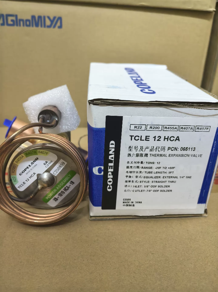

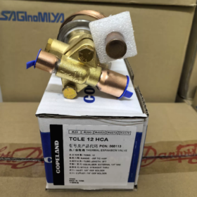
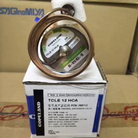
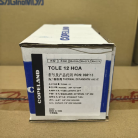
TCLE 12 HCA
- TCL: T-Series Take-Apart Válvula de expansão termostática
- E: External Equalizer
- 12: Nominal Capacity: 12 US Tons (Standard Rating for R22)
- H: Refrigerant Code → R22 / R407C
- C: Charge Type; UM: Non-MOP (Standard Charge)
OEM Part Number (PCN): 057003
- Especificações principais
Nominal Capacity: 12 TR (≈35.2 kW) @ R22 air conditioning standard condition
Compatible Refrigerants: R22, R407C
Conexão: ODF brazed connections
Entrada: 5/8″ ODF
Tomada: 7/8″ ODF
Construção: Take-apart modular design (power assembly + cage assembly + corpo da válvula; components replaceable individually)
Flow Feature: Bi-Flow, suitable for air-source heat pumps
Superaquecimento: Externally adjustable
Pressão Máxima de Trabalho: 450 psig
Bulb Charge: Standard charge, No MOP protection
Application Conditions: Medium-temperature air conditioning, commercial chillers, rooftop units, air-source heat pumps
- Recursos do produto
- Serviceable take-apart structure: Cage or power assembly can be replaced separately without full valve replacement upon failure;
- Bi-directional throttling: Single valve controls refrigerant flow in both cooling and heating cycles, ideal for heat pump systems;
- Stainless steel power element with superior corrosion resistance;
- External superheat adjustment screw for convenient on-site commissioning;
- Classic commercial TXV from ALCO (formerly Emerson Alco Controls) T-series.
- Seleção & Diretrizes de Substituição
- ❌ Not applicable for R410A. Select models with corresponding refrigerant codes for R410A;
- Distinguish HCA (Non-MOP) and HC (MOP-equipped); the two variants cannot be exchanged arbitrarily;
- Similar models within the series: TCLE10HCA (10TR), TCLE7-1/2HCA (7.5TR);
- External equalizer line must be installed and routed to the suction line downstream of the sensing bulb at evaporator outlet;
- Secure sensing bulb tightly against upper section of suction line; fully insulate bulb assembly and avoid direct airflow impact.
- Aplicações Típicas
Air-source heat pumps, commercial central air conditioning, rooftop air conditioning units, refrigeradores de água, medium-temperature commercial refrigeration equipment.
Complete Installation Procedure for Emerson TCLE-12HCA
(External Equalizer, Bi-Flow, Take-Apart ALCO TXV)
The TCLE is an external equalized, bi-flow, modular take-apart thermostatic expansion valve. Critical installation points: valve flow direction, thermal protection during brazing, sensing bulb positioning, external equalizer routing. Improper handling will lead to liquid slugging or unstable refrigerant feed.
- Inspeção Pré-Instalação
- Verifique o modelo: TCLE-12HCA (R22/R407C, Non-MOP, External Equalizer). Do not use on R410A systems;
- Inspect sensing bulb and capillary tube for cracks, kinks or damage; minimum bend radius for capillary ≥50 mm;
- Confirm piping layout: Install filter drier + sight glass upstream of the valve to prevent debris blockage of the cage;
- Critical note: Remove the top power assembly before brazing (TCLE take-apart design) to prevent high temperature damage to bulb charge inside the diaphragm.
- Valve Body Installation Requirements
- Direção do Fluxo: Strictly follow the arrow marking on valve body! Refrigerant enters via 5/8″ inlet and exits from 7/8″ outlet; reverse installation is prohibited.
- Posição de montagem
Install as close as possible to evaporator distributor inlet; minimize piping distance;
Preferred orientation: Montagem vertical (power assembly upward); horizontal installation is acceptable, inverted mounting is not recommended.
- Mandatory Brazing Specifications (Highest Priority)
Fully wrap valve body with wet rags and keep moist during brazing; valve body temperature must not exceed 120°C;
Do not direct torch flame onto valve body or power assembly; aim flame toward copper tubing;
Purge piping with 0.05~0.15 MPa dry nitrogen during brazing to avoid oxide scale entering the valve;
Allow natural cooling after brazing; rapid quenching with cold water is forbidden; refit power assembly only after complete cooling.
- Torque Specification: Tighten power assembly flange to 35 N·m. Do not over-tighten to avoid flange cracking.
- Sensing Bulb Installation (Determines stable valve regulation)
- Location Requirements
Mount on horizontal straight section of suction line at evaporator outlet, as close to evaporator as possible; maintain ≥1.2 m distance from compressor suction port; avoid elbows, valves and oil traps.
- Mounting Angle Rules for Horizontal Piping
Suction line OD <25 milímetros: Secure sensing bulb at 12 o’clock position (top of pipe)
Suction line OD >25 milímetros: Secure sensing bulb at 4 ou 8 o’clock position (45° below horizontal) to avoid oil accumulation at pipe bottom interfering temperature reading
- Requisitos de contato
Polish copper pipe surface to remove oxide and grease;
Ensure full curved-surface contact between sensing bulb and tubing; fasten with stainless steel hose clamp; thin layer of thermal grease is optional;
Plastic cable ties are not allowed.
- Capillary Tube Arrangement
Lay capillary loosely with natural coils; avoid tension and sharp kinks;
Prevent capillary from contacting valve body to avoid temperature interference;
If sensing bulb is installed higher than valve power assembly, route capillary upward into an inverted U loop, preventing liquid charge inside bulb from flowing back.
- Thermal Insulation
Wrap sensing bulb and adjacent pipe section with closed-cell insulation to block direct ambient airflow.
- External Equalizer Line Connection
(TCLE external equalizer valve; missing or misrouted equalizer will cause severe malfunction)
❗Mandatory: External equalizer line must be connected; blocking the port is strictly prohibited!
- Tap Point Location: 80~120 mm downstream of sensing bulb (toward compressor) on suction line
✅ Correct sequence: Evaporator Outlet → Sensing Bulb → Equalizer Tap Point → Compressor
❌ Proibido: Equalizer tap upstream of sensing bulb!
- Tap Orientation: Route equalizer tubing upward from the top of suction line to prevent oil draining into equalizer capillary and blockage.
- Tubing: Use 1/4″ copper tubing; keep length as short as practicable; allow slight downward gradient, avoid U-shaped oil traps.
- Apply cooling protection during brazing equalizer line; purge debris after welding.
- System Leak Test & Pre-Start Procedure
- Complete all brazing work, conduct pressure holding leak test with dry nitrogen at 2.5~3.0 MPa; confirm zero leakage on valve body, equalizer line and pipe joints;
- Thoroughly evacuate the refrigeration system;
- The adjustment screw is factory preset for standard superheat. Do not adjust immediately upon initial startup. Allow stable operation for 20~30 minutes before fine-tuning;
Regras de ajuste (Hexagonal Screw):
Clockwise rotation → Higher superheat (reduced refrigerant feed)
Counter-clockwise rotation → Lower superheat (increased refrigerant feed)
Adjust maximum 1/4 turn each time; wait for system stabilization before further modification; avoid large single adjustments.
- Operações Proibidas (Linhas Vermelhas de Instalação)
- Brazing valve body or power assembly without wet rag cooling; will permanently disable thermostatic element;
- Omission or blockage of external equalizer line;
- Mount sensing bulb at locations with liquid or oil accumulation; do not expose bulb to direct fan airflow;
- Bend or squeeze sensing bulb capillary tube;
- Do not install valve upstream of solenoid valve or filter drier. Liquid line sequence: Receiver → Filter Drier → Sight Glass → TXV → Evaporator.
- Additional Notes for Heat Pump Units
The TCLE-12HCA supports bi-directional flow for air-source heat pump heating & cooling cycles:
Suction piping switches mode between heating and cooling. Sensing bulb and equalizer tap must be installed on the fixed evaporator side (indoor/outdoor heat exchanger outlet), not downstream of four-way reversing valve.
TCLE-12HCA (R22/R407C) Standard Superheat Setting & On-Site Commissioning Guide
- Definição Básica
Superheat = Measured Suction Line Temperature at Evaporator Outlet − Saturation Temperature Corresponding to Evaporating Pressure
Evaporator saturation temperature: Look up from R22 refrigerant property table according to suction pressure reading.
- Target Superheat Values
1) Standard Air-Cooled Chiller / Commercial Air Conditioning (Modo de resfriamento)
✅ Target static superheat: 5~7 K (5~7 ℃)
2) Air-Source Heat Pump (Modo de resfriamento)
✅ Target static superheat: 6~8 K
Do not set below 4 K: High risk of liquid refrigerant returning and compressor liquid slugging;
Do not set above 10 K: Underutilized evaporator heat transfer area, insufficient cooling capacity and excessive discharge temperature.
⚠️ TCLE-12HCA is Non-MOP version. Without maximum operating pressure limitation, liquid slugging risk rises under low load; avoid excessively low superheat setting.
- Standard On-Site Measurement Procedure
- Stabilize unit operation: Full fan speed, steady load, continuous operation ≥20 minutes;
- Measure suction line surface temperature at sensing bulb position (attach temperature probe tightly to copper pipe with insulation);
- Measure suction pressure at external equalizer tap point for highest accuracy and eliminate piping pressure drop error;
- Find saturation temperature from suction pressure, then calculate superheat.
- TCLE Adjustment Screw Operation Rules
Adjustment bolt is located below power assembly (hex drive):
Clockwise rotation → Higher spring preload → Higher superheat → Less refrigerant supply
Counter-clockwise rotation → Lower spring preload → Lower superheat → More refrigerant supply
⚠️ Critical Operation Rules
- Máximo 1/4 turn per adjustment. Half turn or larger single rotation is forbidden;
- Wait 10~15 minutes after each adjustment until system stabilizes before re-measurement;
- Factory preset superheat is approximately 6 K. Run trial operation first; avoid immediate adjustment on startup.
- Visual Judgement via Frost Pattern (Auxiliary Method without Gauge/Thermometer)
Condição normal (Superheat 5~7 ℃)
Uniform condensation or light frost on evaporator coil; condensation extends gradually from evaporator outlet toward compressor along suction line, no frost on compressor housing.
Insufficient Superheat (Excessive Refrigerant Feed, Hazardous)
Heavy frost spreads along suction line all the way to compressor suction port and compressor shell; risk of liquid slugging. Immediately turn clockwise to raise superheat.
Excessive Superheat (Insufficient Refrigerant Feed)
Frost only appears on front section of evaporator; rear coil remains unfrosted; suction line dry and warm; insufficient cooling capacity and high discharge temperature. Turn counter-clockwise to reduce superheat.
- Correct & Incorrect Installation Reference for Sensing Bulb & Equalizer (Refer to Diagram)
- Figure (um): Small-diameter suction line, bulb mounted at pipe top (12 horas) → ✅ Correct
- Figure (b): Large-diameter suction line, bulb mounted at 45° horizontal lower position (4/8 horas) → ✅ Correct, avoids oil accumulation interference
- Figure (c): ❌ Incorreto: External equalizer tap upstream of sensing bulb
- Figure (d): ✅ Correto: Equalizer tap downstream of sensing bulb (80~120 mm spacing)
- Figure (e): ❌ Incorreto: Sensing bulb installed after oil trap; oil accumulation distorts temperature reading
- Figure (f): Recommended layout: Sensing bulb first, equalizer tap approx. 100 mm downstream
Non-negotiable rule for TCLE external equalizer TXV:
Gas flow sequence: Evaporator Outlet → Sensing Bulb → Equalizer Tap → Compressor. Sequence cannot be reversed!
- Solução de problemas comuns de comissionamento
- Instável, fluctuating superheat
Check loose sensing bulb, damaged insulation or direct fan airflow;
Inspect equalizer line for flattening or internal blockage;
Verify low refrigerant charge or clogged filter drier.
- Superheat remains high after repeated counter-clockwise adjustment
Possible cage assembly blockage; clogged liquid line filter;
Undersized valve capacity;
Confirm valve body not installed in reverse direction.
- Liquid slugging occurs immediately after slightly lowering superheat
Verify external equalizer line is fully unobstructed;
Poor system oil return or liquid accumulation inside evaporator;
Do not set superheat below 4 K.
- Extra Commissioning Tips for Heat Pump Units
Dual-mode heating & cooling units:
Do not adjust cooling TXV under heating operation! Switch to cooling mode and wait for stable conditions before commissioning.
Large pressure differential exists between heating and cooling modes; prioritize achieving qualified superheat under cooling mode.





NH42-63-318x560.png "Chaves de transferência automática tipo PC CHINT (ATS)NH42-63/4SZ")



