 Contator,disjuntor,sensor,Codificador,CLP,Conversor

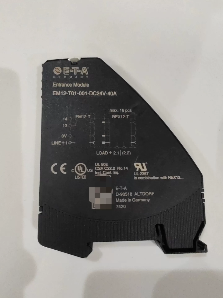


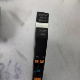
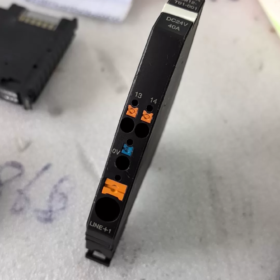
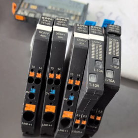
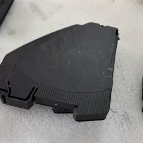
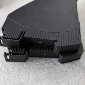
(Modelo Completo: EM12-T01-001-DC24V-40A)
- Informações Básicas
Marca: ETA Alemanha
Série: Sistema modular de distribuição de energia CC REX12-T
Nome do produto: Módulo de alimentação principal / Módulo de distribuição de barramento de energia
Aplicativo: Unidade de entrada principal para sistema protetor de circuito eletrônico REX12-T, que distribui uniformemente a energia do barramento positivo DC24V para uma linha completa de protetores multicanal
- Detalhamento do código do modelo
`EM12-T01-001`
- EM12: Série de módulos de alimentação combinada com REX12
- T: Tipo de sinal analógico padrão (sem comunicação IO-Link; equipado com contato de alarme coletivo passivo Si)
- 01: Versão com alimentação de pólo positivo único
- 001: Versão básica de hardware com padrão DC24V, 40Especificações
Especificações completas do sufixo:
CC24V: Tensão operacional nominal
40UM: Corrente de entrada total máxima do módulo
- Parâmetros elétricos principais
| Item de parâmetro | Valor da especificação |
| Tensão nominal | CC24V, faixa de operação DC18~30V |
| Corrente de entrada total máxima | 40UM |
| Consumo de energia estática sem carga | 10mA típico |
| Proteção contra polaridade reversa | Diodo anti-reverso integrado |
| Buffer de queda de tensão | 10EM (nenhum alarme falso para queda de tensão de curto prazo) |
| Contato de alarme Si | Contato passivo normalmente aberto; carga DC30V/0,5A, condução mínima 10V/1mA |
| Método de fiação | Terminais de mola push-in sem ferramentas, fio de cobre máximo de 10mm² |
| Tensão suportável dielétrica | Entrada/Saída AC2000V para 1 minuto |
| Resistência de Isolamento | ≥100MΩ @500VCC |
- Ambiental & Dimensões Mecânicas
Montagem: Trilho DIN padrão de 35 mm
Dimensões Gerais: L12,4 mm × A98 mm × D80 mm
Temperatura operacional: -25℃ ~ +60 ℃
Temperatura de armazenamento/transporte: -40℃ ~ +85 ℃
| Classe de Proteção | IP20 (apenas para uso interno do gabinete) |
| Certificações | UL508A, CSA, CE, RoHS, ALCANÇAR |
- Funções principais
- Distribuição Central de Energia do Barramento
Conecte a fonte de alimentação externa de 24 VCC a este módulo. Barramentos metálicos integrados na lateral fornecem energia automaticamente em paralelo para todos os protetores de circuito REX12-T conectados em série no lado direito do trilho sem fiação de módulo cruzado.
- Alarme de falha coletiva global (Contato Si)
Uma vez que qualquer protetor REX12 desarme devido a sobrecarga ou curto-circuito, o contato Si passivo interno abre. Ele pode ser conectado ao PLC ou a luzes indicadoras para obter um sinal de falha unificado para toda a linha de circuitos.
- Proteção contra polaridade reversa & Resistência à flutuação de tensão
Pólos de alimentação positivos e negativos invertidos não danificarão o módulo. O buffer de queda de tensão de 10ms evita alarmes falsos causados por queda instantânea de tensão nas fontes de alimentação chaveadas.
- Compatibilidade de Expansão
Conexão em série ilimitada de disjuntores eletrônicos REX12 de canal único/duplo no lado direito. Vários módulos EM12-T01 podem ser conectados em paralelo para expandir a capacidade total de corrente.
- Cenários típicos de aplicação
24Distribuição de carga VDC em gabinetes de controle industriais: Saídas CLP, servoacionamentos, sensores, válvulas solenóides, robôs, distribuição de energia CC a bordo para transporte ferroviário, caixas de controle elétrico para máquinas de construção.
- Comparação com modelos da mesma série
- EM12-T01-001: Tipo analógico padrão apenas com contatos de alarme passivos, nenhuma função de comunicação
- EM12D-T: Versão de comunicação inteligente com suporte para IO-Link/Modbus RTU, capaz de ler corrente do canal e códigos de falha
- EM12-T00: Versão simplificada sem contatos de alarme
- PM12-T: Módulo de expansão potencial para extensão de barramento multifilar
- Nome completo padrão do pedido
Modelo de pedido completo: EM12-T01-001-DC24V-40A
SKUs de estoque de referência para distribuidores: DigiKey 302-1471-ND, RS 175-0362
Especificação de instalação completa para ETA EM12-T01-001-DC24V-40A
- Formulário de montagem padrão
Montagem Padrão Exclusiva: Trilho DIN padrão TH35-7.5 de 35 mm (EN50022)
Sem fixação por parafuso de base ou opções de montagem na parede; apenas instalação com clipe em trilho DIN. Somente montagem horizontal lado a lado é permitida; vertical, a instalação invertida ou inclinada é proibida.
Dimensões gerais: L12,4 mm × A98 mm × D80 mm, largura de módulo único, perfeitamente conectado lado a lado com disjuntores REX12 da mesma série.
- DIN Rail Clip-In Installation Steps (Operação de desligamento necessária!)
- Pré-processamento ferroviário
Adote trilho padrão de aço/alumínio TH35 e rebarbe após o corte. Monte o trilho horizontalmente com espaçamento dos parafusos de fixação ≤250 mm para evitar tremores e deformações.
- Module Clip-In
Prenda o slot superior do módulo na borda superior do trilho DIN, pressione a parte inferior do módulo suavemente até que um “clique” som indica bloqueio completo. Verifique se não há folga vertical e se o módulo não pode ser levantado.
- Regras básicas de layout do sistema
EM12-T01 deve ser instalado no início mais à esquerda de todo o circuito REX12 como ponto de entrada de energia principal;
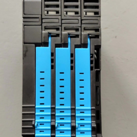
Encaixe o barramento metálico lateral à direita do módulo contra o barramento esquerdo do próximo disjuntor REX12, feche a trava de conexão lateral para realizar a fonte de alimentação do barramento paralelo;
Um único EM12-T01 suporta máximo 40 disjuntores eletrônicos REX12 conectados em série;
Expansão multicircuito: Vários módulos EM12-T01 devem fornecer energia de forma independente; a interconexão direta lado a lado de vários módulos EM12 é proibida.
- Especificação de desmontagem
Desconecte a alimentação principal primeiro. Use uma chave de fenda para soltar a trava inferior e levante o módulo para removê-lo. A desmontagem de módulos conectados em série sob alimentação ativa é estritamente proibida, o que cortará o barramento e causará falha de energia do circuito.
- Instalação de fiação (Compatível com entrada de cabo superior/inferior)
Zonas Terminais & Especificações de bitola de fio
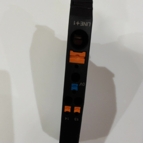
- LINHA+ (24V entrada positiva principal, fonte de alimentação primária)
Fio aplicável: 0.5~10mm² fio de cobre multifilar, Terminal de parafuso M4, torque recomendado 1,2N·m
- 0V (Terminal negativo CC comum)
Fio aplicável: 0.14~2,5 mm²
- E (Contato passivo de alarme de falha coletiva)
Fio aplicável: 0.14~2,5 mm², carga máxima DC30V/0,5A
Requisitos de fiação
Estão disponíveis entradas de cabo superior e inferior; select wiring direction according to cabinet layout;
Fios de entrada principais pesados (≥6mm²) devem ser roteados separadamente dos fios de sinal Si em diferentes dutos de cabos para reduzir a interferência;
Feche as travas laterais de interconexão dos módulos somente após toda a fiação estar concluída, então ligue a energia.
- Dissipação de Calor & Requisitos de instalação de espaçamento
- Reserve ≥50 mm de espaço de ventilação vertical entre os componentes superiores e inferiores no mesmo trilho DIN;
- Este módulo é uma unidade de alimentação de alta corrente 40A; não o monte perto de componentes geradores de calor, como fontes de alimentação de alta potência, inverters and contactors;
- Nenhuma lacuna de isolamento obrigatória para vários módulos densamente dispostos, mas a temperatura ambiente do gabinete deve ser controlada ≤60℃;
- A ventilação por convecção natural deve ser garantida dentro do gabinete; instalar ventiladores de resfriamento para gabinetes selados sem ventilação.
- Instalação Reforçada para Vibração & Condições de trabalho severas
Para cenários de alta vibração, incluindo máquinas-ferramentas, trânsito ferroviário e máquinas de construção:
- Instale batentes finais do trilho DIN em ambas as extremidades do trilho para evitar o deslizamento horizontal dos módulos;
- Anexe almofadas de absorção de choque de borracha de 3mm na parte traseira do trilho para reduzir a ressonância;
- Verifique regularmente o torque do terminal e o status de travamento da trava.
- Proibições estritas de instalação
- Vertical, instalação invertida ou inclinada acima de 45° é proibida, which deteriorates heat dissipation and triggers overheat protection;
- Conexão ao vivo, é proibido desconectar ou desmontar módulos conectados em série; corte de energia no barramento causará desligamento do equipamento;
- Installing EM12 in the middle or right side of REX12 circuit is forbidden, levando à falha na fonte de alimentação do barramento;
- Fios de entrada mais finos que 0,5mm² ou mais grossos que 10mm² são proibidos, resultando em crimpagem de terminal solto e superaquecimento;
- Instalação direta sem proteção em ambientes empoeirados, névoa de água ou ambientes de condensação são proibidos (IP20 somente para uso interno do gabinete);
- A corrente de carga total de longo prazo do único EM12 nunca deve exceder o valor nominal de 40A.
- Materiais de instalação auxiliares recomendados
- Batentes de fixação final em trilho DIN (evitar deslizamento do módulo);
- Chave de fenda de torque M4 (unified terminal tightening torque 1.2N·m);
- Terminais de crimpagem para fios multifilamentos para evitar curto-circuito causado por fios de cobre espalhados;
- Separação de dutos de cabos: Passe os fios principais de alimentação de 24 V e os fios de sinal de alarme Si separadamente.
Parâmetros de temperatura de ETA EM12-T01-001-DC24V-40A (Padrão do manual do fabricante original)
- Temperatura ambiente normal de operação
Faixa operacional padrão: -30 ℃ ~ +60 ℃, a condensação é estritamente proibida durante a operação (EM 60204-1 padrão de aplicação de gabinete)
23℃ temperatura ambiente: A operação contínua em plena carga a 40A é permitida
40℃: Reduza a corrente nominal para 95% (38UM)
50℃: Reduza a corrente nominal para 90% (36UM)
60℃: Reduza a corrente nominal para 85% (34UM)
Instalação densa lado a lado de vários módulos: Desclassificar ainda mais a corrente para 80% do valor acima
- Redução da temperatura de altitude (Condições de trabalho em alta altitude)
≤2000m: Suporte completo para faixa operacional de -30~+60℃
3000eu: Temperatura ambiente máxima permitida reduzida para +55℃
4000eu: Temperatura ambiente máxima permitida reduzida para +50°C
- Armazenar & Temperatura de Transporte (Status de desligamento)
Temperatura de armazenamento: -40 ℃ ~ +70 ℃ (com embalagem original de fábrica)
Limite de armazenamento de longo prazo: -40℃ ~ +85 ℃ (apenas exposição de curto prazo, não é permitido ligar)
- Instalação & Fiação da temperatura ambiente
Ambiente operacional para montagem e fiação: +5 ℃ ~ +60 ℃. A desmontagem e montagem do terminal não são recomendadas abaixo de 5°C; fios frios tendem a desgastar e causar torque terminal instável.
Limitações de uso suplementares
- A classificação IP20 aplica-se apenas ao uso interno do gabinete; não pode ser exposto diretamente a ambientes externos com temperaturas extremas, névoa de água ou poeira;
- Para gabinetes selados sem ventiladores de resfriamento forçado, Recomenda-se que a temperatura ambiente do gabinete de longo prazo seja controlada ≤50 ℃;
- Nenhuma falha funcional ocorre ao iniciar a baixa temperatura de -30 ℃, mas pré-aqueça sob condição sem carga por um período antes da operação em plena carga sob estado frio.





NH42-63-318x560.png "Chaves de transferência automática tipo PC CHINT (ATS)NH42-63/4SZ")



