 Contator,disjuntor,sensor,Codificador,CLP,Conversor


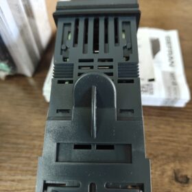
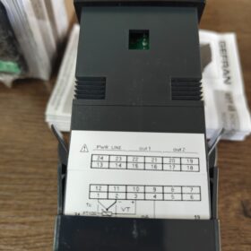
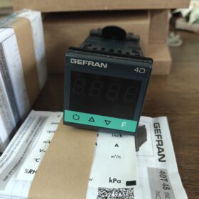
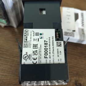
| Campo | Código | Descrição |
| Série | 40T | Indicador universal de processo / unidade de alarme (mostrar & apenas alarme, NÃO é uma temperatura PID controlador) |
| Tamanho do painel | 48 | 48×48mm (1/16 DE, recortar: 45×45mm) |
| Exibir dígitos | 4 | 4-display LED de dígitos |
| Fornecimento do transmissor | 0 | Sem fonte de alimentação do sensor integrada |
| Saída 1 + Saída 2 | RR | OUT1=Relé; OUT2=Relé |
| Avaliação: 5UM / 250VAC, Normalmente aberto (NÃO) contato | ||
| 3terceira saída | 0 | Sem saída do terceiro relé |
| Entrada digital / Retransmissão analógica | 0 | Sem DI digital, sem saída de retransmissão analógica de 4 ~ 20mA |
| Interface de comunicação | 0 | Sem comunicação RS485 (Modbus não suportado) |
| Fonte de energia | 0 | 11~27 VAC/VDC fonte de alimentação AC/DC universal |
| (Sufixo 1 = 100 ~ 240 VCA de potência de ampla faixa) |
- Principais Especificações Técnicas
- Entrada universal (Configurável através de botões do painel frontal)
Termopar: K, J., E, T, R, S, B, N, etc..
IDT: Pt100 (2-arame / 3-arame)
Sinais lineares: 4~20mA, 0~20mA, 0~10V, 0~60mV, etc..
- Precisão: ±0,2%FS ±1 dígito
- Proteção do painel frontal: IP65
- Profundidade geral: 99 milímetros
- Ciclo de amostragem: 15~120ms ajustável
- Funções: Exibição do valor do processo, até 2 alarmes independentes, detecção de quebra/curto-circuito do sensor; Sem função de controle PID
- Notas principais
✅ Posicionamento: Indicador digital com alarme, não pode controlar diretamente a temperatura; apenas para monitoramento + alternar saída de alarme
❌ Sem comunicação RS485, não é possível conectar ao barramento PLC
❌ Sem saída de retransmissão de 4~20mA
❌ Sem fonte de alimentação do sensor de 24 V integrada
✅ Compatível com DC24V / Fonte de alimentação AC24V
- Alternativa Comum & Modelos variantes da série
40T-48-4-00-RR-0-0-0-1: Fonte de alimentação alterada para 100~240VAC
40T-48-4-00-RR-0-2-0-0: Equipado com saída de retransmissão analógica adicional de 4~20mA
40T-48-4-24-RR-0-0-0-0: Fonte de alimentação do transmissor de 24V integrada
PERIGO 40T-48-4-00-RR-0-0-0-0 Parâmetros de dimensão
- Dimensão geral (L × A × Profundidade)
48 milímetros × 48 milímetros × 99 milímetros
Padrão 1/16 Fator de forma DIN
- Dimensão do recorte de montagem do gabinete
45 milímetros × 45 milímetros
Tolerância de usinagem recomendada: +0.5milímetros
- Informações Complementares
Avaliação do painel frontal: IP65
Profundidade traseira do instrumento (dentro do armário): 99milímetros; reserve ≥105 mm de espaço interno para fiação durante o projeto do gabinete
O modelo 40T-96 da mesma série é a versão horizontal 96×48, não confunda
Precisão de medição GEFRAN 40T-48
Precisão nominal oficial
- Termopar / Entrada RTD
±0,2% da escala completa (FS) ±1 dígito
Condição de teste: Temperatura ambiente 25℃
- Entrada Analógica Linear (mV, 0~10V, 0/4~20mA)
±0,2% da escala completa (FS) ±1 dígito
Deriva de temperatura
Quando a temperatura ambiente se desvia de 25℃:
≤ ±0,01% FS / ℃
Notas Suplementares Importantes
- Resolução: 4-display LED de dígitos, unidade mínima de exibição 1 dígito
- A precisão refere-se apenas ao próprio instrumento, excluindo erro do sensor
- A precisão da atuação do alarme segue a precisão da medição sem desvio adicional
- Limitação: Sem regulamentação PID, apenas medição & alarme; sem índice de precisão de controle
Exemplo prático
Faixa definida como 0~200℃:
Erro máximo de medição do instrumento ≈ ±0,4℃ ±1 dígito
PERIGO 40T-48-4-00-RR-0-0-0-0 Configuração de saída
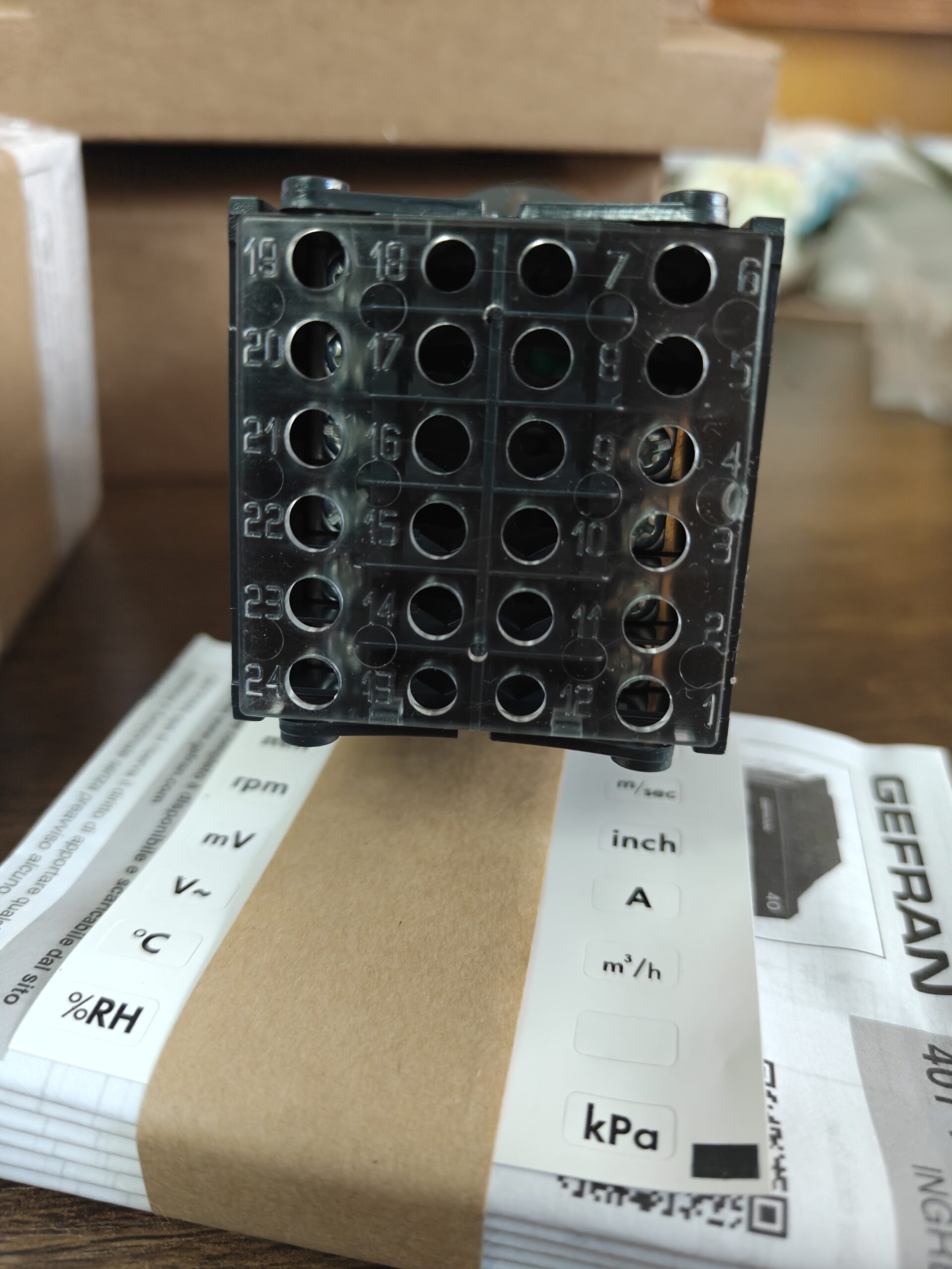
Segmento de saída do modelo: …00-RR-0-0-0-0
- RR = SAÍDA1, SAÍDA2
- 7o dígito `0`: Sem terceira saída
- 8o dígito `0`: Sem saída de retransmissão analógica
- 9o dígito `0`: Sem interface de comunicação
- Saídas integradas
2 Saídas de relé
Formulário de contato: Normalmente aberto (NÃO)
Avaliação de contato: 5UM / 250VAC; 5UM / 30CCV (carga resistiva)
Aplicativo: Alarme de limite alto/baixo, sinal do interruptor de limite; pode acionar pequenos contatores e luzes indicadoras
✅ Recurso: Saídas de alarme independentes; valor e modo de alarme (limite alto/baixo, alarme de desvio, etc.) pode ser configurado separadamente
- Saídas NÃO disponíveis neste modelo
- ❌ Não 4~20mA / 0Saída de retransmissão analógica de ~10V (dígito = 0, não 2)
- ❌ Sem saída de tensão do inversor SSR
- ❌ Sem comunicação Modbus RS485
- ❌ Sem saída lógica de transistor NPN/PNP
- ❌ Sem saída de controle PID (esta unidade é apenas para monitoramento & alarme, incapaz de regular a temperatura)
- Combinações de saída opcionais da série (para referência de seleção de modelo)
RR: Relé duplo (modelo atual)
RS: Relé OUT1 + Saída da unidade OUT2 SSR
SS: Saídas duplas de drive SSR
Sufixo dígito `2`: Saída de retransmissão analógica extra de 4~20mA
Dígito do sufixo `4`: Interface Modbus RTU RS485
Lembrete de fiação
Os relés são contatos secos passivos. Fonte de alimentação externa é necessária. O instrumento não fornece energia interna aos contatos; não conecte diretamente aos circuitos do sensor.
PERIGO 40T-48-4-00-RR-0-0-0-0 Modo de operação do relé
✅ Os relés OUT1 e OUT2 suportam configuração personalizada via painel frontal
Perceber: Este é um indicador de alarme digital sem controle PID. Os relés só podem ser usados como saídas de alarme, não saídas de controle de temperatura.
- Modos de alarme configuráveis (Independente para dois relés)
- Alarme Alto Absoluto (Oi)
O relé é energizado quando o ponto de ajuste do valor medido
- Alarme Absoluto Baixo (Lo)
O relé é energizado quando o valor medido < ponto de ajuste
- Alarme de Desvio (Positivo / Desvio Negativo)
Disparo baseado no desvio relativo ao ponto de ajuste (comumente usado para monitoramento diferencial)
- Alarme de quebra de sensor
O relé é ativado em circuito aberto do termopar/Pt100 ou sinal acima da faixa
- Parâmetros Auxiliares Ajustáveis
Histerese de Alarme: Impedir o ciclo rápido do relé (conversa)
Trava de alarme: O relé permanece energizado após o disparo do alarme; é necessária a reinicialização manual do painel
Supressão de alarme de inicialização: Desative temporariamente os alarmes na inicialização para evitar disparos falsos
Lógica de contato: Selecione energizado em alarme OU desenergizado em alarme
- Limitações Críticas
- Os contatos de hardware são contatos secos normalmente abertos. O hardware físico não pode ser alterado para Normalmente Fechado; “desenergizado em alarme” é realizado puramente pela lógica do software.
- Não pode ser configurado como saída de controle liga/desliga PID (40Série T é indicador, não controlador PID como 400 / 2500 série).
- OUT1 e OUT2 funcionam de forma independente; combinação como limite alto em um canal e limite baixo no outro é suportada.
- Procedimento de acesso aos parâmetros
Pressão longa [Tecla F] para 2 segundos → Digite a senha padrão 99
Navegue dentro do grupo de menu `CFG`:
o.1: Ponto de ajuste do alarme OUT1
o.2: Ponto de ajuste do alarme OUT2
Selecione o tipo de alarme, histerese, função de trava e supressão de inicialização nos submenus correspondentes





NH42-63-318x560.png "Chaves de transferência automática tipo PC CHINT (ATS)NH42-63/4SZ")



