 Contator,disjuntor,sensor,Codificador,CLP,Conversor

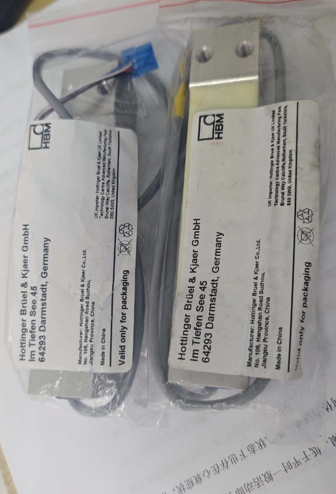

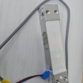
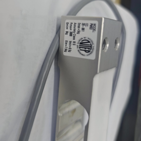
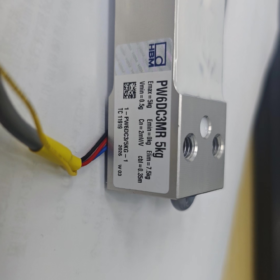
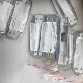
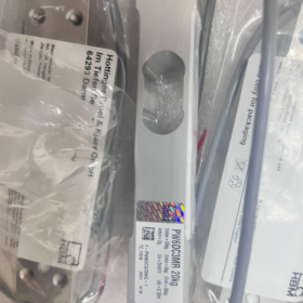
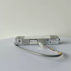
PW6DC3MR/XXkg
PW6D: Série de produtos, tipo de ponto único otimizado para pesagem dinâmica de alta velocidade
C3: Classe de precisão de 3,000 divisões de verificação de acordo com OIML R60
MR = Multi-faixa: Comparado com a versão C3 padrão, suporta um intervalo mínimo de verificação menor, adequado para instrumentos de pesagem de múltiplas faixas
XXkg: Capacidade nominal (3/5/10/15/20/30/40kg)
Exemplo completo de modelo de pedido: 1-PW6DC3MR/10KG-1
- Especificações principais
- Opções de capacidade
3kg, 5kg, 10kg, 15kg, 20kg, 30kg, 40kg
- Parâmetros Elétricos
Saída nominal: 2.0 mV/V
Resistência de entrada da ponte: ~350Ω
Tensão de excitação recomendada: 5~12V CC (Máx.. 15 Em DC)
Construção: 6-projeto de fio (o cabo pode ser cortado) para eliminar erros de medição causados pela queda de tensão do cabo; compatível com instrumentos de 4 fios
Resistência de Isolamento: >2000 MΩ
- Precisão & Certificações
OIML R60 C3MR, nLC=3000 divisões
Compensação de carga descentralizada em conformidade com OIML R76; dimensão máxima da plataforma para célula de carga única: 300×300mm
Não linearidade / Histerese / Repetibilidade: ≤±0,017%FS
- Mecânico & Especificações Ambientais
Material: Liga de alumínio
Classe de Proteção: IP67
Deflexão nominal: 0.18~0,29mm (Alta rigidez, resposta dinâmica rápida)
Faixa de temperatura compensada: -10 ℃~ +40 ℃
Faixa de temperatura operacional: -10 ℃~ +50 ℃
Sobrecarga Segura: 150%FS; Sobrecarga final: 300%FS
Parafuso de montagem: M6; Torque de aperto recomendado: 10 N·m
- Principais vantagens
✅ Otimizado para pesagem dinâmica: Alta frequência natural, ideal para verificação de peso em alta velocidade e enchimento volumétrico
✅ Compensação de carga descentralizada integrada para minimizar erros de excentricidade da plataforma
✅ Vedação IP67, aplicável em ambientes de produção empoeirados e úmidos
✅ Cabo blindado de 6 fios garante sinal estável para fiação de longa distância
✅ A variante MR multi-range suporta intervalos de verificação menores, compatível com equipamentos de pesagem comercial legalmente verificados
- Aplicações Típicas
Verificadores de peso em linha, máquinas de classificação por peso
Embalagem automática em pequena escala, pó & equipamento de enchimento de partículas
Balanças de plataforma industrial, balanças combinadas com vários cabeçotes
Monitoramento dinâmico de peso em linhas de produção automatizadas
- Definição de fiação (Cabo blindado padrão de 6 fios)
| Sinal | Cor típica do fio |
| +Exc Excitação Positiva | Azul |
| -Exc Excitação Negativa | Preto |
| +Sentido Sentido Positivo | Verde |
| -Sentido Sentido Negativo | Cinza |
| +Sig Sinal Positivo | Branco |
| -Sig Sinal Negativo | Vermelho |
| Escudo | Verde/Amarelo |
Para instrumentos de 4 fios: Curto-circuito +Sense para +Exc, e -Sense para -Exc
- Mesma série & Referências Alternativas
- PW6DC3: Precisão padrão C3 (não RM), menor custo, não pode suportar intervalos de verificação pequenos em vários intervalos
- PW2DC3MR: Célula de carga de ponto único de tamanho menor da HBM, com tamanho de plataforma máximo permitido menor
- Alternativas domésticas: Células de carga C3 de ponto único da Zemic, UM&D, Instrumentos de medição eletrônicos Zhonghang. Verifique o layout do furo de montagem, Classificação mV/V e tamanho máximo da plataforma antes da substituição.
- Precauções de instalação
- As superfícies de montagem devem ser planas e rígidas. Não solde ou bata no corpo da célula de carga.
- Tighten M6 bolts strictly at 10 N·m to avoid thread stripping on aluminum housing.
- Load shall be applied vertically downward; avoid lateral force and torque impact.
- Prevent mechanical bending and tension at the cable outlet; single-end grounding is recommended for shielding.
Complete Load Cell Selection Guide (Illustrated with HBM PW6DC3MR Single-Point Load Cell)
Etapa 1: Confirm Mechanical Structure Type (Highest Priority)
Match load cell structure according to load condition:
| Cenário de aplicação | Tipo recomendado | Applicability for PW6DC3MR |
| Single load cell supporting one platform, checkweigher, small packaging scale | Single-Point Load Cell ✅ | PW6DC3MR is a single-point type. Built-in eccentricity compensation; one platform requires only one load cell |
| Material hoppers, bins, multi-cell platform scales | Viga de cisalhamento / Viga cantiléver | ❌ Not applicable to PW6D |
| Tension weighing, hanging scales | S-Beam Load Cell | ❌ Not applicable to PW6D |
| Heavy-duty truck scales, pesagem de tanques | Column / Spoke Load Cell | ❌ Not applicable to PW6D |
Hard restriction of PW6DC3MR: Maximum platform dimension: 300×300mm. Platform exceeding this size will cause excessive eccentricity error.
Etapa 2: Cálculo de capacidade (Most Common Pitfall in Selection)
Fórmula de cálculo
Rated Capacity of Load Cell ≥ (Platform Dead Weight + Maximum Product Weight) × Safety Factor
Stable static weighing: Safety factor 1.2~1.3
Dynamic checkweighing, material drop impact, vibrating production line: 1.5~2.0 (1.5 recomendado)
Exemplo prático (PW6DC3MR)
Platform dead weight = 1.5kg, maximum product weight = 10kg, inline dynamic checkweighing:
Total load = 1.5 + 10 = 11.5kg; 11.5 × 1.5 = 17.25kg
Priority selection: PW6DC3MR/20KG. Avoid 15kg (insufficient margin) and excessive 30kg capacity (poor resolution for light loads).
⚠️ Two critical rules:
- Do not operate continuously near full capacity;
- Do not oversize capacity excessively, which degrades resolution for low-weight measurement.
Etapa 3: Accuracy Class Selection (C3 / C3MR / Comparação C6)
Veja a série HBM PW6D como exemplo:
- C3: Padrão 3000 divisões, para pesagem industrial em geral, incapaz de atingir intervalos de verificação ultrapequenos
- C3MR (Seu modelo): Variante multi-gama, Certificação OIML R60, suporta intervalo mínimo de verificação menor (Mínimo)
✅ Adequado para equipamentos que necessitam de certificação metrológica legal, verificação de peso em alta velocidade, enchimento volumétrico e alta resolução de exibição (medição em nível de grama)
- C6: 6000 divisões, maior precisão, custo mais alto, requisitos mais rigorosos para rigidez de montagem e ambiente operacional
Regra de seleção rápida para C3 vs C3MR
Equipamento requer certificação metrológica comercial, controle de peso de alta precisão, intervalo de pequena escala (nível de grama) → PW6DC3MR
Apenas monitoramento de processos internos, não é necessária certificação de pesagem, requisitos de precisão soltos → PW6DC3 (versão padrão)
Principais indicadores de precisão a serem revisados: Não linearidade, histerese, repetibilidade, rastejar, erro de desvio de temperatura.
Etapa 4: Ambiente Operacional, Material & Classe de Proteção
- Material
PW6DC3MR: Liga de alumínio; adequado para alimentos secos padrão e oficinas automatizadas.
Para lavagem, úmido ou corrosivo / ambientes de névoa salina: Prefira células de carga de ponto único de aço inoxidável.
- Classe de Proteção
PW6D: IP67, à prova de poeira e à prova de respingos; NÃO para submersão permanente.
Para equipamento totalmente lavado ou instalação subaquática: São necessárias células de carga hermeticamente seladas IP68.
- Faixa de temperatura
Faixa compensada: -10~+40℃; operação prolongada fora desta faixa leva a grave desvio de zero. Modelos personalizados de ampla temperatura necessários para condições extremas de temperatura.
- Proteção contra explosão: Para áreas explosivas perigosas, use células de carga certificadas intrinsecamente seguras. O PW6DC3MR padrão não é à prova de explosão.
Etapa 5: Correspondência de parâmetros elétricos com instrumento
- Sensibilidade: PW6DC3MR = 2.0 mV/V, a especificação mais comum para pesagem industrial; confirmar a compatibilidade do instrumento.
- Tipo de fiação: PW6D adota 6 fios (com linhas de feedback Sense)
Instrumento que suporta 6 fios: Fiação completa para eliminar queda de tensão do cabo
Instrumento que suporta apenas 4 fios: Curto-circuito +Sense para +Exc, -Sentido para -Exc
- Tensão de excitação: Recomendado 5~12 V CC, máximo 15 Em DC
- Resistência da ponte: ~350 Ω de resistência de entrada, compatível com transmissores de pesagem padrão
Etapa 6: Verificação de Dimensões Mecânicas (Facilmente esquecido)
- Comprimento total, altura, passo do furo de montagem, especificação de thread (PW6D usa parafusos de montagem M6)
- Verifique o espaço de instalação mecânica
- Garanta a transmissão vertical da carga; o projeto da estrutura deve eliminar a força lateral e o torque
Padrão de torque de montagem PW6D: Torque de aperto do parafuso M6 10 N·m. A carcaça de alumínio corre o risco de danificar a rosca sob torque excessivo.
Etapa 7: Distinguir Dinâmico / Cenários de aplicativos estáticos
Pesagem Estática (Escala de plataforma de armazém): O padrão C3 é suficiente; priorizar a estabilidade zero a longo prazo
Pesagem Dinâmica (Verificador de peso em linha, Classificação on-line): PW6DC3MR preferido; alta frequência natural otimizada, resposta rápida e resistência à vibração
Lista de verificação de erros comuns de seleção
❌ Considere apenas o peso máximo do produto sem incluir o peso morto da plataforma
❌ Use célula de carga de ponto único PW6D para plataformas maiores que 300×300 mm, resultando em erro de excentricidade excessivo
❌ Adote fator de segurança de apenas 1.2 sob impacto dinâmico, levando à fadiga do elemento elástico e danos permanentes
❌ Adquira C3 padrão em vez de C3MR quando for necessária certificação de pesagem, não cumprir o requisito mínimo de intervalo de escala
❌ Selecione célula de carga de alumínio IP67 para ambiente úmido de lavagem, levando à entrada de água a longo prazo e falha prematura
❌ Capacidade superdimensionada causa leituras instáveis e baixa resolução para produtos leves
Modelo de seleção rápida (Pronto para uso direto)
- Estrutura: Ponto Único ✅ (Plataforma ≤300×300 mm)
- Carga Total: Plataforma ____kg + Produto máximo ____kg = ____kg × Fator de segurança ____ = ____kg → Modelo selecionado PW6DC3MR/____kg
- Precisão: Certificação metrológica necessária? Sim → C3MR; Não → C3
- Ambiente: Oficina seca, IP67 aceitável; Lavagem / ambiente corrosivo → mudar para célula de carga de aço inoxidável
- Elétrica: Suportes de instrumentos 2.0 mV/V; confirme a fiação de 6 ou 4 fios
- Instalação: Verifique a dimensão, Espaço de montagem M6, estrutura de transmissão de força vertical
Como determinar a posição de montagem das células de carga
Explicação baseada na célula de carga de ponto único HBM PW6DC3MR (plataforma unicelular); regras gerais para plataformas de pesagem multicelulares também estão incluídas.
- Distinguir dois tipos estruturais: Ponto Único vs Multi-Célula
(1) Célula de carga de ponto único (PW6DC3MR, célula única suportando uma plataforma)
Células de carga de ponto único apresentam compensação de carga descentralizada integrada.
Posição de montagem padrão: Centro geométrico da parte inferior da plataforma
✅ Arranjo ideal:
Alinhe o centro do furo de suporte de carga da célula de carga com o centro do comprimento e largura da plataforma.
Dimensão máxima permitida da plataforma: 300 × 300 milímetros (Limite de especificação PW6D)
⚠️ Restrições Críticas:
Se a célula de carga se desviar do centro:
O erro de excentricidade aumenta
Leituras inconsistentes quando o peso é colocado nos quatro cantos
Mesmo a instalação centralizada não pode compensar o erro se a plataforma exceder o limite máximo de dimensão do fabricante
Método prático: Desenhe duas diagonais da plataforma retangular; a interseção é a posição de montagem central.
(2) Estrutura Multicelular (3/4 Células de carga cantilever/feixe de cisalhamento, Balanças de plataforma, Funis de armazenamento)
A posição de montagem segue o princípio da distribuição uniforme da carga de acordo com o centro de gravidade
- Plataforma retangular com quatro células de carga: Dispostos simetricamente perto de quatro cantos
- Caixa de armazenamento circular com três células de carga: Distribuído uniformemente em um layout de triângulo equilátero
- Alvo: A carga transportada por cada célula de carga deve ser tão uniforme quanto possível em condições de carga vazia e plena
- Cinco princípios universais para todos os sistemas de pesagem
Princípio 1: O centro de gravidade combinado deve estar dentro do envelope de suporte das células de carga
- Condição descarregada: O centro de gravidade do peso próprio da plataforma está dentro da área de suporte
- Condição totalmente carregada: Quando o material é colocado na excentricidade máxima, o centro de gravidade geral combinado permanece dentro do envelope de suporte
Se o centro de gravidade se mover para fora da região de suporte: Risco de tombamento da plataforma, e a célula de carga suporta enorme força lateral e torque, levando a danos permanentes.
Princípio 2: Elimine a força lateral e o torque nas células de carga
As células de carga devem suportar apenas força de compressão vertical
❌ Condições proibidas:
Força componente lateral gerada pela posição de montagem distorcida
Torque induzido por rigidez insuficiente da estrutura de suporte
✅ Solução:
Projetar paradas mecânicas para restrição horizontal. Mantenha uma pequena folga vertical; os batentes não devem suportar carga vertical.
Princípio 3: Garanta a transmissão de força vertical
A superfície de suporte de carga da célula de carga deve estar paralela à superfície inferior da plataforma de pesagem.
A base de montagem deve ser plana e rígida; evite suspensão de placas finas e contato local concentrado.
A carcaça de alumínio PW6DC3MR proíbe carregamento de contato pontual.
Princípio 4: Evite fontes fortes de vibração e tensão de expansão térmica
Seleção da posição de montagem:
Mantenha distância de fontes de vibração fortes, como motores e rolos transportadores
A expansão/contração térmica de estruturas longas pode puxar a célula de carga; estrutura de suporte deslizante é necessária quando necessário
Princípio 5: Evite tensão de tração na saída do cabo
A saída do cabo do PW6DC3MR fica na extremidade do sensor.
Requisito de arranjo: Reserve loops de cabo frouxos; evite tensão e dobras repetidas na raiz do cabo para evitar quebra interna do fio.
- Posicionamento passo a passo para plataforma de ponto único (PW6DC3MR)
- Medir a dimensão da plataforma externa: Comprimento L × Largura L
- Calcular coordenadas centrais: L/2, C/2
- Alinhe o centro do furo de suporte da célula de carga com o ponto central calculado
- Verificação da dimensão da plataforma:
≤300×300mm: Instalação centralizada normal
>300×300mm: PW6D não pode ser usado. Mude para uma célula de carga de ponto único maior ou uma solução multicélula
- Verificação de teste de peso:
Coloque pesos de calibração sequencialmente nos quatro cantos da plataforma e observe o desvio de leitura.
Erro excessivo de quatro cantos indica posição deslocada da célula de carga ou plataforma superdimensionada.
- Operação de posicionamento de quatro cantos para plataforma multicelular (4 Exemplo de célula de carga)
- Layout simétrico; quatro pontos de apoio formam um retângulo
- Deixe uma margem adequada entre os pontos de apoio e a borda da plataforma; evite colocar muito perto das bordas
- Nivelamento bruto sob carga vazia com pré-carga
- Execute a calibração com erro de quatro cantos após carregar pesos em cada canto
- Instale batentes mecânicos para evitar que a plataforma deslize sob impacto
- Erros comuns de posição de montagem
- Célula de carga de ponto único instalada longe do centro da plataforma → leituras inconsistentes nos quatro cantos
- Plataforma superdimensionada ainda usando célula de carga de ponto único PW6D → erro de excentricidade excessivo
- Rigidez insuficiente da estrutura de suporte; a deformação da estrutura sob carga induz torque na célula de carga
- Paradas mecânicas bloqueadas; a expansão térmica cria força adicional levando a um desvio zero contínuo
- Células de carga dispostas muito próximas das bordas; o centro de gravidade se move para fora do envelope de suporte quando o material é colocado excentricamente
- A tensão da correia cria uma força de tração horizontal transferida para a célula de carga em controladores de peso em linha (Estrutura independente necessária para isolar a tensão da correia)
- Conselhos adicionais para o seu equipamento (Verificador de peso com PW6DC3MR)
Para controladores de peso em linha: A estrutura do transportador de correia não deve ser fixada rigidamente à plataforma de pesagem.
O motor do transportador e a tensão da correia produzem força de tração horizontal contínua.
Solução recomendada: Somente a plataforma de pesagem transporta produtos; a estrutura do transportador fica independente no solo para isolar a força horizontal.





NH42-63-318x560.png "Chaves de transferência automática tipo PC CHINT (ATS)NH42-63/4SZ")



