 Contator,disjuntor,sensor,Codificador,CLP,Conversor

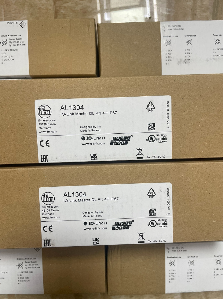

Posicionamento Básico do Produto
Nome completo do modelo: AL1304 DataLine IO-Link Mestre DL PN 4P IP67
Marca: IFM (Alemanha)
Perfil principal: 4-porta Classe A mestre IO-Link com barramento PROFINET + portas Ethernet duplas independentes para IoT JSON/MQTT. É um módulo de E/S distribuída em campo com classificação IP67, permitindo instalação externa direta na máquina sem gabinetes de controle.
Detalhamento do código do modelo
AL: Campo da série DataLine mestre IO-Link
13: Versão do barramento PROFINET
04: 4-portas IO-Link classe A do canal
Sem marcação de sufixo = Caixa IP67 laranja industrial padrão
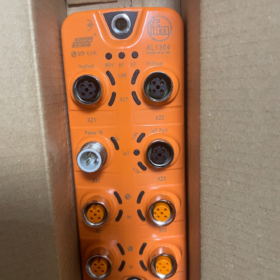
- Layout da porta de hardware principal (8 × Conectores M12)
Definições de porta de cima para baixo:
- X1: Porta Ethernet PROFINET (M12 com código D, 100 Mbps) → Conecte-se à rede de controle PLC
- X2: Porta Ethernet IoT independente (M12 com código D) → Rede isolada de TI/nuvem para upload de dados de sensores via JSON/MQTT
- X3~X6: 4 × Portas IO-Link Classe A (M12 5-pin A-coded)
Each port integrates 2DI + 1FAZER, with a total of 8DI / 4DO for the unit
- X7: Entrada de energia (M12 A-coded, 24 CCV)
- X8: Ethernet Daisy-Chain Output (M12 com código D) → For bus daisy-chain expansion
- Principais especificações elétricas
3.1 Fonte de energia
Tensão operacional: 18~30V CC (padrão 24 V industrial DC)
Max Total Power Consumption: ≤6 W
Power Connector: M12 A-coded, with reverse polarity and short-circuit protection
3.2 IO-Link Channels (4 × Class A)
IO-Link Version: V1.1, Conformance Class C; suporta IRT, MRP, CiR and S2 redundancy
Digital Inputs per Port: 2 DE (Compatível com PNP/NPN)
Alto nível: 11~30V CC; Baixo nível: 0~5 V DC
Digital Output per Port: 1 FAZER (PNP)
Max Load per Channel: 300 mA, with short-circuit/overload protection
Max Current per Channel: 0.3 UM; total output current limiting for four channels
3.3 Desempenho de comunicação
PROFINET Control Network (X1/X8)
Velocidade: 100Base-TX, 100 Mbps
Topologias Suportadas: Topologia de linha, Redundância de anel MRP
Compatibilidade: Siemens S7-1200, S7-1500, CPU 315, CPU 400 and other PROFINET controllers
Supporting File: GSDML file available for download with official manuals
Independent IoT Ethernet (X2, Rede isolada por hardware)
Protocolos: JSON TCP/IP, MQTT
Velocidade: 10/100 Negociação automática de Mbps
Vantagem Central: Isolamento de hardware entre rede de controle e rede de nuvem de TI, impedindo a intrusão de rede externa em sistemas de controle PLC. Os dados brutos do sensor são carregados diretamente nas plataformas MES/nuvem sem ocupar o tempo de ciclo do PLC.
3.4 Ambiental & Especificações Mecânicas
Classe de Proteção: IP67 (impermeável e à prova de poeira, montagem direta em corpos de máquinas)
Temperatura operacional: -25℃ ~ +60 ℃
Temperatura de armazenamento: -40℃ ~ +80 ℃
Material da Habitação: Poliamida PA, resistente a vibrações e resistente a óleo
Padrões de vibração: EM 60068-2-6, EM 60068-2-27
Montagem: 2 através de furos para parafusos M4; montado na parede ou montado na máquina
- Principais destaques funcionais
- Arquitetura de rede dupla isolada
PROFINET é dedicado ao movimento PLC e controle lógico; a porta IoT independente carrega separadamente dados de diagnóstico, como temperatura, contadores e vibração sem interferência mútua, em conformidade com os padrões de segurança de rede de fábrica.
- 4 Canais IO-Link com DI/DO integrado
Cada canal pode conectar diretamente sensores IO-Link (pressão, fluxo, fotoelétrico, codificadores, módulos de temperatura) ao mesmo tempo que fornece entradas e saídas digitais integradas, eliminando a necessidade de blocos terminais extras.
- Recursos PROFINET avançados completos
Sincronização IRT em tempo real, Redundância de anel MRP, Modificação da configuração on-line do CiR, Diagnóstico de rede SNMP, adequado para linhas de produção de alta velocidade e estações de trabalho robóticas.
- Software de configuração gratuito moneo|configurar gratuitamente
Verifica automaticamente todos os dispositivos IO-Link, importação de arquivos IODD com um clique, download de parâmetros em lote, diagnósticos on-line e alarmes de falha.
- Diagnóstico Abrangente
Upload em tempo real de curto-circuito na porta, quebra de cabo, perda de dispositivo, sinais de subtensão e tempo limite de comunicação para PLC; logs JSON de falha são enviados simultaneamente por meio da porta IoT.
- Embalagem Padrão & Acessórios opcionais
Entrega padrão
1 × Unidade Principal AL1304
Manual de instalação rápida impresso
Acessórios que podem ser encomendados separadamente
Cabos PROFINET M12 com código D (direto / angular)
Cabos de alimentação com codificação M12 A
Tampas de proteção contra poeira nas portas
Cabos Ethernet em cadeia
- Comparação de seleção de séries (Série AL13xx PROFINET)
| Modelo | Portas IO-Link | Porta IoT | Classe de Proteção | Cenários típicos de aplicação |
| AL1304 | 4 × Class A | Portas Ethernet duplas independentes | IP67 | Estações de trabalho pequenas, máquinas autônomas, aplicações com ≤4 sensores |
| AL1306 | 8 × Class A | Portas Ethernet duplas independentes | IP67 | Estações multisensoriais, aquisição distribuída de dados em linhas de produção |
| AL1307 | 8 × Class A | Portas Ethernet duplas independentes | IP69K | Comida & ambientes farmacêuticos com lavagem de alta pressão |
- Indústrias de aplicação típicas
Soldagem automotiva & linhas de revestimento, centros de máquinas-ferramenta
Linhas de produção de embalagens, linhas de classificação logística
Moldagem por injeção, borracha & equipamento de plástico, pequenas máquinas de automação personalizadas
Upload de dados de equipamentos na nuvem, Projetos de aquisição de dados MES
Manual completo de instalação do IFM AL1304 IO-Link Master
Informações do documento
Modelo: AL1304 (DL PN 4P IP67)
Versão: Instalação Padrão Original & Manual de operação
Aplicativo: Mestre IO-Link montado em parede/máquina no local com PROFINET isolado + Redes duplas IoT
Classe de Proteção: IP67, montagem direta ao ar livre/máquina sem gabinetes de controle
Índice
- Requisitos de segurança obrigatórios
- Inspeção Pré-Instalação & Lista de ferramentas
- Especificações de instalação mecânica (Dimensões, Consertando, Torque, Aterramento)
- Definição de porta & Especificações de fiação do conector M12
- Procedimentos passo a passo de fiação elétrica
- Cabeamento & Especificações anti-interferência EMC
- Lista de verificação de inspeção pré-ligação
- Guia de status do indicador LED de inicialização
- Especificações de desmontagem da unidade
- Proibições de instalação & Prevenção de falhas
- Lista de acessórios opcionais originais
1 Requisitos de segurança obrigatórios (Deve ser seguido)
⚠️ Avisos de perigo crítico
- Corte tudo 24 Alimentação V antes de qualquer instalação, remoção ou desmontagem da fiação. A conexão/desconexão a quente de conectores M12 é estritamente proibida, pois queimará chips de driver de porta.
- A fonte de alimentação é de segurança SELV/PELV extra baixa 24 CCV; conexão com 220 VAC ou 380 A alimentação principal VAC é proibida.
- A base de montagem metálica deve ser aterrada de forma confiável para evitar descargas eletrostáticas e danos causados por surtos nos canais Ethernet e IO-Link.
- Para aplicações de alimentos/lavagem, evite a pulverização direta de água de alta pressão nas raízes do conector. Selecione AL1307 (IP69K) para exposição prolongada à lavagem.
- Faixa de temperatura ambiente: Operando -25℃ ~ +60℃; Temperatura de instalação ≥0℃ para evitar o endurecimento da vedação e a entrada de água em baixas temperaturas.
2 Inspeção Pré-Instalação & Lista de ferramentas
2.1 Inspeção de desembalagem
- Verifique a unidade AL1304 quanto a rachaduras, amassados e conectores deformados; confirme se os anéis de vedação FKM estão intactos e sem danos.
- Conteúdo padrão: Unidade principal, manual de instalação rápida impresso. Cabos e tampas contra poeira não estão incluídos e devem ser encomendados separadamente.
- Verifique a marcação do modelo AL1304, confirmar 4 Canais IO-Link Classe A e portas Ethernet duplas com código D.
2.2 Ferramentas necessárias
Chave de torque (0.5~3 N·m), Parafusos M5, arruelas planas/arruelas de pressão
14 chave de boca mm (para apertar conectores M12)
Multímetro (24 Teste de continuidade V e curto-circuito)
Abraçadeiras, braçadeiras de cabo, cabos Ethernet industriais blindados
3 Especificações de instalação mecânica
3.1 Dimensões gerais da unidade
152 milímetros (H) × 59.3 milímetros (C) × 38.4 milímetros (D)
3.2 Métodos de montagem: Parede / Montagem do corpo da máquina (Sem clipes para trilho DIN)
- Dois furos passantes de montagem na parte traseira superior e inferior da unidade; seguro com 2 × Parafusos M5 + arruelas planas.
- Torque de aperto padrão: 1.8 N·m. O torque excessivo é proibido para evitar deformação da carcaça e falha da vedação.
- Requisitos de superfície de montagem: Placa metálica plana livre de rebarbas e contaminação por óleo. Ângulo máximo de inclinação ≤90°. Não monte de cabeça para baixo com os conectores voltados para cima (risco de entrada de acúmulo de água).
- Requisitos de aterramento: Os dois parafusos de montagem M5 também servem como terminais de aterramento da unidade; a base metálica deve ser conectada ao terra de proteção PE. Para placas de montagem não metálicas, passe um fio de aterramento separado para o barramento PE.
3.3 Requisitos de folga de montagem
Reserve ≥30 mm de folga vertical acima e abaixo da unidade para dissipação de calor; ≥20 mm de folga lateral para evitar acumulação de calor.
Mantenha uma distância mínima de 150 mm do inversor e dos cabos de alimentação do servo para reduzir a interferência eletromagnética.
4 Definição completa da porta da unidade (8 Conectores M12 de cima para baixo)
| Número da porta. | Tipo de conector | Codificação | Descrição da função |
| X1 | Ethernet M12 de 4 pinos | Codificado D | Rede de controle PROFINET (conectar ao CLP) |
| X2 | Ethernet M12 de 4 pinos | Codificado D | Rede IoT isolada independente (Carregamento em nuvem MQTT/JSON/MES) |
| X3/X4/X5/X6 | Link IO M12 de 5 pinos | Codificado A | 4 Canais IO-Link Classe A, cada um com 2DI+1DO integrado |
| X7 | Alimentação M12 de 5 pinos | Codificado A | 24 Entrada de energia VCC |
| X8 | Ethernet M12 de 4 pinos | Codificado D | Saída em cadeia PROFINET |
4.1 Torque de aperto geral do conector M12 (Padrão de fábrica)
Torque básico manual: 0.6 N·m
Ambientes severos de vibração/óleo: 1.2~1,5 N·m (apertado com 14 chave mm)
Não ligue se os anéis de vedação estiverem faltando; A proteção IP67 será perdida.
5 Procedimentos passo a passo de fiação elétrica
5.1 Porta de alimentação X7 (Pinagem IO-Link padrão M12 A de 5 pinos)
Definição de alfinete (visto da frente do plugue):
1: Marrom +24 Em DC
2: Preto DI1 (entrada digital compartilhada para canais)
3: Azul 0 V GND
4: Branco DI2 (entrada digital compartilhada para canais)
5: Saída cinza PNP DO (máx. 300 mA)
Faixa de fonte de alimentação: 18~30 VCC, consumo total de energia ≤6 W. Fonte de alimentação com polaridade reversa integrada, proteção contra curto-circuito e sobrecorrente.
5.2 Portas IO-Link X3~X6 (Codificação A independente de 5 pinos por canal)
Cada canal fornece fonte de alimentação independente, Comunicação IO-Link e DI/DO integrado sem terminais externos:
Pino1: 24 Alimentação do sensor V L+
Pino2: DE (Entrada compatível com PNP/NPN)
Pino3: 0 VL-
Pino 4: Linha de comunicação IO-Link (C/Q)
Pino 5: Saída PNP DO, 300 Limitação de corrente em mA por canal
5.3 Cabos Ethernet industriais de 4 pinos com código D para X1/X2/X8
Pino1: Transmissão TD+ +
Pino2: Transmissão TD –
Pino3: RD+ Receber +
Pino 4: RDReceber –
As camadas de blindagem devem ser aterradas em ambas as extremidades para suprimir a interferência do motor. A rede X2 IoT e a rede de controle X1 são isoladas por hardware, sem intercomunicação.
6 Cabeamento & Especificações anti-interferência EMC
- Cabos de alimentação separados (servo, inversor) e cabos IO-Link/Ethernet em bandejas de cabos diferentes com um espaçamento mínimo de 150 milímetros. Use bandejas metálicas blindadas para separação se for inevitável encaminhar juntas.
- Raio de curvatura mínimo dos cabos M12 ≥ 5 × diâmetro externo do cabo; flexões bruscas e compressão nas raízes do conector são proibidas.
- Limites de comprimento de cabo:
Cabo IO-Link: ≤20m
Cabo Ethernet industrial PROFINET: ≤100m (100 Mbps)
- Todas as portas sobressalentes não utilizadas devem ser equipadas com tampas originais contra poeira e à prova d'água, caso contrário, a classificação IP será invalidada.
- A blindagem de todos os cabos Ethernet blindados deve ser cravada em 360° no invólucro metálico do conector com aterramento de ponto único.
7 Lista de verificação obrigatória de inspeção completa antes da ligação
- Fixação Mecânica: Dois parafusos M5 apertados 1.8 N·m; unidade fixa sem oscilação.
- Teste de aterramento: Multímetro para verificar a continuidade entre a base de montagem e o terra de proteção PE; resistência de aterramento <4 Ω.
- Estanqueidade do cabo: Todos os conectores M12 apertados com 0,6~1,5 N·m sem folga.
- Teste de curto-circuito: Desconecte a fonte de alimentação, use o multímetro para confirmar que não há curto-circuito entre X7 Pin1 e Pin3, e nenhum curto-circuito ao terra no Pino 1/Pino 3 de todos os canais IO-Link.
- Segregação de Rede: X1 conectado à rede de controle PLC, X2 para rede IT/MES independente; conectar ambas as portas ao mesmo switch é proibido.
- Todas as portas sobressalentes equipadas com tampas contra poeira.
8 Guia de status do indicador LED de inicialização
LEDs de status integrados no painel frontal para diagnóstico rápido de falhas após a inicialização:
- LED de energia PWR (Verde Sólido): Fonte de alimentação normal; Desligado = Sem energia / Curto-circuito; Piscando = Subtensão <18 V
- NET1 (X1 PROFINET):
Sólido ativado: Link estabelecido; Piscando: Troca de dados; Desligado: Quebra de cabo / Nenhum dispositivo conectado
- NET2 (Rede IoT X2):
Sólido ativado: Link de rede de TI estável; Piscando: Carregamento de dados MQTT/JSON
- LEDs dos canais CH1~CH4 (X3~X6):
Verde Sólido: Comunicação normal do dispositivo IO-Link
Vermelho piscando: Curto-circuito na porta, quebra de cabo ou perda de dispositivo
Desligado: Nenhum dispositivo conectado ao canal
9 Especificações de desmontagem da unidade
- Primeiro corte o 24 V fonte de alimentação principal e aguarde 30 segundos para descarga.
- Afrouxe todos os conectores M12 com um 14 chave mm; não puxe os cabos com força.
- Afrouxe os dois parafusos de montagem traseiros M5 e remova a unidade.
- Instale tampas contra poeira nas portas imediatamente após a desmontagem para proteger os anéis de vedação.
10 Proibições de instalação & Prevenção de falhas
❌ Proibido: Monte a unidade de cabeça para baixo com os conectores voltados para baixo (água acumulada em tomadas)
❌ Proibido: Aperte os parafusos de fixação acima 1.8 N·m; ocorrerão rachaduras na carcaça e vazamento de água
❌ Proibido: Conectores M12 hot plug/desconecte; chips de comunicação vão queimar
❌ Proibido: Roteamento paralelo próximo de cabos de alimentação e cabos IO, causando perda de pacotes de comunicação
❌ Proibido: Conecte as portas X1 e X2 ao mesmo switch, quebrando a segurança do isolamento da rede
❌ Proibido: Operação externa de longo prazo sem tampas contra poeira; poeira causará curto-circuitos nas portas
Prevenção comum de falhas de instalação:
- Desconexões frequentes de comunicação: Verifique o torque do conector, blindagem do aterramento e distância de separação dos cabos de alimentação
- Alarmes persistentes de curto-circuito na porta: Verifique a fiação do sensor IO-Link e garanta carga ≤300 mA
- Dispositivo PROFINET não detectado: Verifique o arquivo GSDML, Endereço IP, nome do dispositivo e cabo Ethernet com código D
- Falha no upload de dados IoT: X2 utiliza um segmento de rede independente sem conflito de IP com a rede PLC
11 Acessórios opcionais originais (Encomendado separadamente)
- Cabos Ethernet PROFINET retos/angulares com codificação D M12 (2 eu / 5 eu / 10 eu)
- Cabos de alimentação de 5 pinos com codificação A M12
- Cabos de sensor IO-Link padrão de 4/5 núcleos
- Pó & tampas de porta impermeáveis (canal único / conjunto completo para unidade)
- Suportes de montagem em aço inoxidável (para equipamentos de alta vibração)
Notas de Tradução
- Termos profissionais de automação industrial adotam expressões industriais de padrão internacional (Link IO, PROFINET, PNP/DI/DO, MRP, TRI, CiR, MQTT, JSON, AUTO/PELV, EMC, GSDML, SIM, Trilho DIN, OU terra etc.)
- Torque, temperatura, comprimento, as unidades atuais mantêm símbolos métricos internacionais consistentes com as planilhas de dados oficiais em inglês do IFM
- Codificação do conector M12 (Codificado A / Codificado D), etiquetas de pinagem e classe de proteção IP67/IP69K seguem a terminologia padrão original de fábrica
- Tabelas, símbolos de aviso, marcas proibidas e estrutura do documento correspondem totalmente ao layout do texto original em chinês para uso direto em manuais técnicos estrangeiros





NH42-63-318x560.png "Chaves de transferência automática tipo PC CHINT (ATS)NH42-63/4SZ")



