 Contator,disjuntor,sensor,Codificador,CLP,Conversor

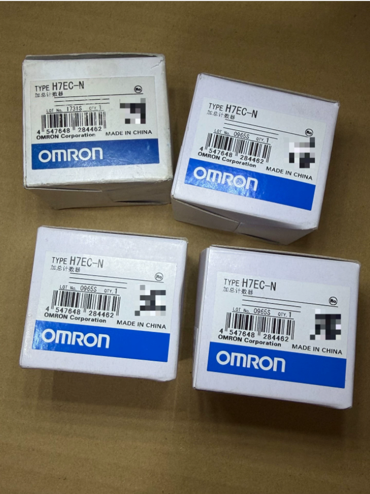

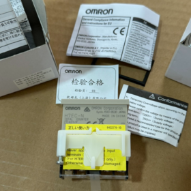
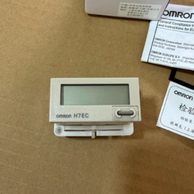
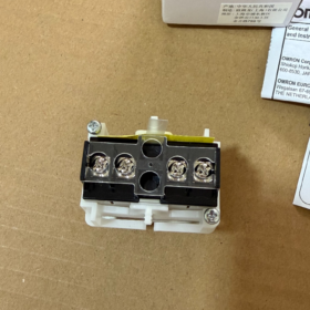
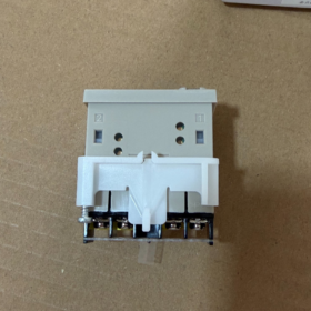
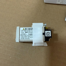
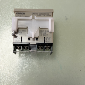
Autoalimentado (bateria de lítio embutida), 8-contagem total de dígitos, Sem tensão(contato seco) entrada, montagem embutida em painel, contando dados retidos após perda de energia
- Explicação do código do modelo
H7EC: 8-dígito contador totalizador série
N: 1/32 Montagem em painel DIN, autoalimentado por bateria interna, Sem tensão (contato seco) entrada
Sufixo B: Carcaça preta; não -B = caixa cinza claro
Distinguir modelos semelhantes:
H7EC-NV: Entrada de tensão DC4.5-30V (NPN/PNP)
H7EC-NFV: Entrada de tensão de ampla faixa AC/DC
H: Com luz de fundo (a luz de fundo requer alimentação externa DC24V; contagem ainda alimentada por bateria interna)
- Principais Especificações Técnicas
| Item | H7EC-N |
| Mostrar | 8LCD de dígitos, altura do caractere:8.6 milímetros, exibição de supressão de zero, sem luz de fundo |
| Faixa de contagem | 0-99999999, Somente contagem crescente |
| Tipo de entrada | Entrada de contato seco sem tensão (interruptores, contatos de relé) |
| Máx.. Velocidade de contagem | 30 Hz / 1 kHz, selecionável via interruptor DIP lateral |
| Largura Mínima do Sinal | 30Hz:16.7 EM; 1kHz:0.5 EM |
| Reiniciar | Front‑panel manual reset + reinicialização do terminal externo; key‑lock switch to disable front‑panel reset key |
| Minimum Reset Pulse Width | ≥20 ms |
| Fonte de energia | Built‑in 3V lithium battery Y92S‑36; não é necessária alimentação externa; backup de dados; replaceable battery |
| Battery Service Life | Approx.10 years standby; approx.5 years continuous counting @30Hz; approx.4 years continuous counting @1kHz |
| Instalação | Flush panel mount, 1/32 DIN; Cut‑out:45×22.2 mm; Dimensão geral:48×24×48.5 mm |
| Panel Protection Rating | IP66 (with waterproof gasket fitted) |
| Temperatura operacional | -10~+55℃ |
| Terminais | Terminais tipo parafuso |
- Wiring Instructions for H7EC-N (No-voltage Input)
This unit requires NO external operating power. Only counting-signal and reset-signal wiring needed.
- Count Input Terminals: Connect to switch or relay dry-contacts. One complete count is triggered by contact closure followed by opening.
- Reset Terminals: Short-circuit external dry-contact to perform reset. A tecla de reinicialização manual também está disponível no painel frontal.
- Chaves DIP de montagem lateral:
VELOCIDADE: Selecione a velocidade de contagem:30Hz/1kHz
BLOQUEIO DE CHAVE: Proteção de chave. ON=Reinicialização do painel frontal bloqueada, apenas reinicialização externa disponível; OFF=Reinicialização do painel frontal habilitada.
⚠️Importante: H7EC-N não pode conectar sensores de proximidade NPN/PNP diretamente! Usar H7EC-NV (modelo de entrada de tensão) para sensores de proximidade.
- Precauções de aplicação
- Nova unidade: Remova a folha isolante da bateria, caso contrário, nenhuma exibição e nenhuma contagem.
- Especificação da bateria: Use Y92S-36 dedicado (3Bateria V Li-Mn). Não substitua outros tipos de bateria. Display piscando indica bateria fraca. Os dados de contagem serão perdidos durante a substituição da bateria.
- Esta é a entrada de contato seco. Evite interferência de tensão induzida. Mantenha os cabos de sinal separados dos cabos de alta potência.
- Redefinir condição: KEY-LOCK deve estar DESLIGADO para que a reinicialização do painel frontal funcione. A reinicialização externa é independente da configuração de bloqueio de teclas.
- Sem luz de fundo embutida. Para versão com luz de fundo, selecione a série H7EC-NV-H; a luz de fundo precisa de alimentação externa DC24V.
- Solução de problemas comuns
- Sem contagem: Verifique a chave DIP de configuração de velocidade; verifique se a largura do pulso atende aos requisitos mínimos; confirme se a folha isolante da bateria foi removida.
- Redefinição do painel frontal ineficaz: Verifique a chave DIP KEY-LOCK, definido como DESLIGADO.
- Visor piscando: Bateria interna fraca, substituir Y92S-36.
- Espúrio / contagem aleatória: O cabo de sinal corre em paralelo com a fiação de energia de alta tensão, causando interferência induzida; use cabo blindado ou reduza o comprimento da fiação.
- Referência de substituição doméstica
8-Contador totalizador de dígitos 48×24mm com bateria embutida, entrada de contato seco. Critérios de seleção principais:
Entrada: Entrada de contato seco sem tensão
Velocidade de contagem comutável entre 30Hz /1kHz
Manual + reinicialização externa, função de bloqueio de teclas, bateria de lítio interna substituível em campo
Dimensão de recorte do painel:45×22.2 mm
Precisão de contagem de Omron H7EC-N
H7EC-N é um contador totalizador acionado por pulso, NÃO é um horímetro. A folha de dados oficial NÃO fornece especificações de erro de contagem percentual ou ppm. (±100ppm é a especificação de precisão de tempo para horímetros da série H7ET e NÃO se aplica aos contadores H7EC.)
- Princípio de contagem
Lógica de contagem: +1 contagem para cada pulso de entrada válido. Pulso válido → contagem de incrementos; pulso inválido → sem incremento. Esta é uma contagem de pulso baseada em eventos, sem erro inerente de medição analógica.
Sob condições válidas de pulso de entrada, erro de contagem teórico zero. Todos os erros práticos se originam de sinais externos, interferência na fiação ou largura de pulso insuficiente.
✅Condições de pulso obrigatórias para contagem confiável
| Contexto | Máx.. Taxa de contagem | Largura Mínima de Pulso (Relação ON/OFF1:1) |
| 30Configuração Hz | 30 pulsos/segundo | ≥16,7ms |
| 1Configuração de kHz | 1000 pulsos/segundo | ≥0,5ms |
Se a largura do pulso de entrada < especificação mínima → pulso não detectado → perda de contagem.
Salto de contato ou interferência elétrica → pulsos falsos extras → contagem excessiva.
Critérios de limite de entrada sem tensão:
SOBRE (gatilho de contagem): Impedância fechada de contato ≤10kΩ
DESLIGADO: Impedância de contato aberto ≥750kΩ, tensão residual ≤0,5V
- Especificações frequentemente confusas
- H7ET-N (Horímetro): Precisão do tempo ±100ppm @25℃, usado para medição de tempo decorrido, não contagem de pulso.
- H7EC-N (Contador): Acumula apenas pulsos de entrada. Nenhum parâmetro “±XX% de precisão”. A confiabilidade da contagem depende inteiramente da qualidade dos pulsos recebidos.
- Fontes práticas de erros no local
- Salto de contato mecânico: Relé / o salto do interruptor de limite gera vários pulsos espúrios → contagem excessiva.
- Largura de pulso insuficiente: Pulso de entrada mais estreito que a especificação mínima → perda de contagem.
- Interferência de fiação: Cabo de sinal roteado ao lado dos cabos de alimentação, tensão induzida causa falso disparo.
- Configuração errada do interruptor DIP de velocidade: Pulsos de alta velocidade aplicados na configuração de 30 Hz → perda massiva de contagem.
- Recomendações práticas para garantir a precisão da contagem
- A frequência de pulso de entrada não deve exceder a configuração de velocidade selecionada. A largura do pulso deve exceder a especificação mínima.
- Adicione circuito de supressão de ressalto RC para contatos mecânicos para evitar contagem excessiva causada por ressaltos.
- Separe a fiação do sinal de contagem dos cabos de alimentação; cabo blindado é recomendado para longos percursos.
- Observe o indicador de ponto decimal do LCD: O ponto decimal pisca ao receber um pulso válido; sem cintilação = o contador não detecta nenhum pulso de entrada.
Comissionamento rápido no local H7EC-N & Procedimento de solução de problemas
H7EC-N: Entrada de contato seco, alimentado por bateria, não é necessário fornecimento externo. Ponto decimal do LCD piscando = pulso de contagem válido recebido; principal indicador de diagnóstico para trabalho de campo.
Sequência de solução de problemas: Bateria & inspeção visual → Configuração da chave DIP → Teste da função de reinicialização → Teste de simulação de sinal de bancada → Teste de sinal de campo real → Mitigação de interferência.
Etapa 1: Solução de problemas sem exibição / problemas de nova unidade
- Confirme se a folha isolante da bateria foi removida. A unidade mostrará uma tela em branco se a folha permanecer ajustada.
- Dígitos piscando: Bateria Y92S-36 fraca. Substitua a bateria; todos os dados de contagem armazenados são perdidos durante a substituição.
- Tela completamente em branco: Bateria com falha; substituir Y92S-36.
⚠️Desconecte toda a fiação antes de substituir a bateria. Use apenas o modelo de bateria especificado.
Etapa 2: Verifique as configurações do interruptor DIP de montagem lateral (crítico)
Dois interruptores DIP localizados na caixa lateral:
- VELOCIDADE (Velocidade de contagem)
30Hz: Para interruptores mecânicos / interruptores de limite, min. largura de pulso ≥16,7ms
1kHz: Para sinais de contato seco de alta velocidade, min. largura de pulso ≥0,5ms
Se a frequência real do sinal exceder a configuração selecionada, pulsos serão perdidos! NÃO selecione 1kHz para interruptores mecânicos; alto risco de contagens excessivas causadas por rejeição.
- BLOQUEIO DE CHAVE (Função de bloqueio de teclas)
DESLIGADO: Chave de redefinição RST do painel frontal habilitada
SOBRE: Chave RST do painel frontal bloqueada, apenas a redefinição do terminal externo funciona. Muitos diagnosticam erroneamente o estado bloqueado como falha de contador.
Etapa 3: Teste de função de reinicialização
- Defina KEY-LOCK como DESLIGADO. Pressione a tecla RST do painel frontal; a leitura deve ser zerada → Redefinição manual funcional.
- Defina KEY-LOCK como LIGADO. A tecla do painel frontal não tem efeito. Terminais de reinicialização externa em curto-circuito por ≥20ms; a leitura deve ser reiniciada → Reinicialização externa funcional.
A reinicialização externa precisa de curto-circuito contínuo de ≥20ms. O toque momentâneo NÃO acionará a reinicialização.
Etapa 4: Teste funcional de bancada do contador (sem fiação de campo)
Simule pulsos de contagem curto-circuitando manualmente os terminais de entrada de contagem
- Curto-circuitar repetidamente e abrir manualmente os terminais de entrada de contagem.
- O ponto decimal do LCD pisca uma vez para cada pulso válido e a contagem aumenta em 1.
✅O ponto decimal pisca e a contagem aumenta: Hardware do contador OK. A falha está na fiação externa / interruptores / sensores.
❌Sem oscilação de ponto decimal: Fiação solta, configuração incorreta do interruptor DIP ou danos ao hardware.
Lembrete importante: H7EC-N é uma entrada de contato seco sem tensão. NÃO conecte diretamente sensores de proximidade NPN/PNP! Use H7EC-NV para entradas de chave de proximidade. Conexão inadequada resulta em contagem errática ou ausência de contagem.
Etapa 5: Diagnóstico de quatro condições típicas de falha
Falha1: Sem contagem, nenhum incremento apesar da atuação do interruptor externo
- Observe o ponto decimal: Sem cintilação → O contador não recebe nenhum sinal válido.
- Verifique o aperto do parafuso do terminal e a continuidade do fio.
- Configuração de VELOCIDADE: Aplicações de chave mecânica configuradas para 30 Hz, não 1kHz.
- Verifique o desempenho do switch com teste de continuidade do multímetro.
- Confirme se a fonte do sinal fornece fechamento de contato seco, não sinal de saída de tensão.
Falha2: Perda de contagem; eventos reais excedem o incremento do contador
- A frequência do sinal de entrada excede o máximo de configuração de VELOCIDADE (por exemplo, sinal de 80 Hz com 30 Hz selecionado → grande perda de pulso).
- Largura do pulso de entrada abaixo da especificação mínima.
- Comutação de mau contato, pulsos válidos incompletos.
Remédio: Reduza a velocidade operacional; ajustar câmera / alterne o tempo para satisfazer o requisito mínimo de largura de pulso.
Falha3: Incremento de contagem espontâneo sem atuação física (falha de campo mais comum)
- Salto de contato mecânico: Relé / o salto do interruptor de limite cria vários pulsos falsos.
✅Solução: Ajustar rede de supressão de ressalto RC em terminais de contato (R≈1k-10k, C≈0,1μF).
- Interferência de fiação: Cabo de sinal de contagem roteado ao longo da fiação de alimentação de 220 V; tensão induzida desencadeia contagens falsas.
✅Solução: Cabos de sinal e alimentação separados; use shielded cable with shield grounded at cabinet-side only; shorten cable runs.
- Leakage current from peripheral equipment produces residual current in open-state condition, causing false triggering.
Fault 4: Front-panel reset key does not zero reading
- Check KEY-LOCK DIP-switch. If set ON, toggle to OFF.
- If front-panel key aging suspected: Test via external-terminal reset. Successful external reset confirms counter hardware integrity.
Step 6: On-site EMC & anti-interference guidelines specific to H7EC-N
- Count-signal cables must NOT share cable trunking with motor, contactor or VFD power cables; maintain ≥10 mm physical separation.
- Use shielded cable for long-distance runs; connect shield to cabinet ground only at cabinet end (counter end ungrounded).
- Always fit RC bounce-suppression for mechanical-contact inputs, especially under 1kHz setting.
- Terminal screw tightening torque 0.98 N·m. Avoid over-torque to prevent terminal damage.
Quick-reference Troubleshooting Mnemonic
Watch decimal-point flicker: flicker = valid pulse received; no flicker = no incoming signal; random increments = interference / salto de contato; reset failure = key-lock engaged; flashing digits = replace battery.
Omron H7EC-N Dimensions (Unidade:milímetros)
- Dimensões Físicas Gerais (L × A × Profundidade)
Front-panel frame: 48(largura) × 24(altura) milímetros (1/32 DIN standard)
Profundidade geral (front-panel surface to rear of terminals): 48.5 milímetros
Complete unit dimension: 48 × 24 × 48.5 mm, weight approx.60 g
- Cabinet Panel Cut-out Dimension (Sheet-metal opening)
45.0(largura) × 22.2(altura) milímetros
Tolerância: width +0.5 mm, height +0.5 mm
Suitable sheet-metal thickness: 1~6 mm
✅Sheet-metal cut-out = 45×22.2 mm. Do NOT cut to 48×24 mm (48×24 is outer frame dimension, not cut-out).
- Notas de instalação
- A classificação de proteção IP66 do painel frontal é perdida quando várias unidades são montadas densamente lado a lado. Mantenha uma folga ≥2,5 mm para desempenho IP66.
- Tamanho do parafuso terminal M3.5, torque de aperto:0.98 N·m.
- H7EC-NV / H7EC-NFV compartilham dimensão física e tamanho de recorte idênticos; a substituição direta de painel a painel é possível.
Memorização Rápida
Tamanho da moldura externa:48×24mm
Recorte em chapa metálica: 45 × 22,2 mm
Folga mínima de profundidade interna do gabinete ≥ 50 mm





NH42-63-318x560.png "Chaves de transferência automática tipo PC CHINT (ATS)NH42-63/4SZ")



