 Contator,disjuntor,inversor solar,medidor elétrico,baterias solares

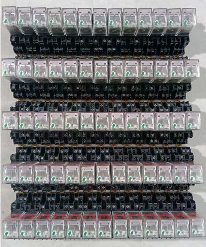

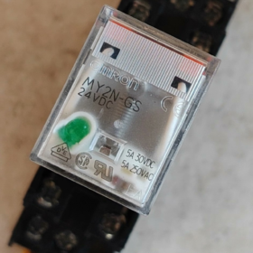
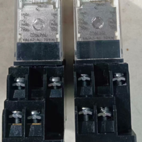
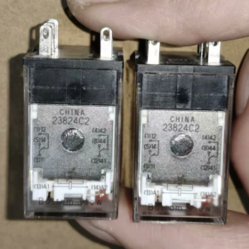
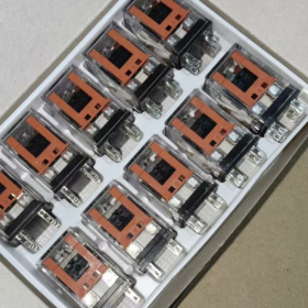
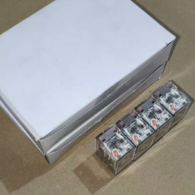
O OMRON MY2N-GS AC220V é um circuito duplo de 2 pólos (DPDT) miniatura de plug-in relé intermediário da série OMRON MY-GS. É o substituto oficial atualizado para o modelo legado clássico MY2N-J. As configurações padrão incluem um indicador LED de operação, indicador de status mecânico e alavanca de travamento de teste manual. Adotando contatos de liga de prata, possui alta confiabilidade, longa vida útil e fiação conveniente. Usado principalmente para amplificação de sinal de saída PLC, comutação de carga e conversão lógica de circuito, é um componente universal fundamental para gabinetes de controle de automação industrial.
- Detalhamento do código do modelo
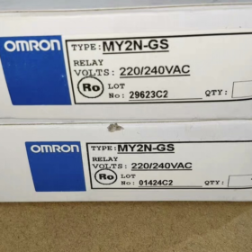
Modelo padrão completo: MY2N-GS AC220/240V
MEU: Série de produtos, relé intermediário de potência miniatura de uso geral
2: Número de conjuntos de contato, 2 conjuntos de contatos de mudança (DPDT, 2 Normalmente aberto + 2 Normalmente fechado)
N: Terminais plug-in padrão com indicador de operação integrado
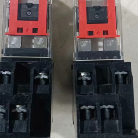
GS: Série de próxima geração (Padrão de Geração). Ele substitui a série MY2N-J original, está equipado com uma alavanca de bloqueio adicional, e oferece durabilidade de contato e desempenho elétrico otimizados.
AC220/240V: Tensão nominal da bobina, CA 220~240V, compatível com fonte de alimentação 50/60Hz.
Notas Suplementares
A maioria dos produtos disponíveis no mercado vem equipada com uma alavanca de travamento por padrão (sufixo -R), suportando testes manuais e bloqueio de contato.
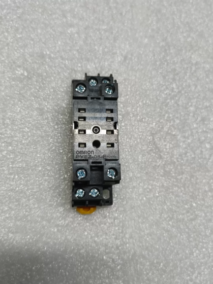
Soquete padrão de 8 pinos compatível: Terminal de parafuso tipo PYF08A, terminal push-in tipo PYF08A-PU.
- Principais Especificações Técnicas
| Categoria | Especificações |
| Configuração de contato | 2 conjuntos de contatos de mudança (DPDT, 2NÃO+2NC) |
| Corrente de contato nominal | 5UM (Carga resistiva AC250V); 5UM (Carga resistiva DC30V) |
| Material de contato | Liga de prata (AgSnO₂) |
| Tensão nominal da bobina | CA 220~240V, 50/60Hz |
| Consumo de energia da bobina | Aprox.. 1.2~1,5VA |
| Tempo de operação | ≤ 20 EM |
| Hora de lançamento | ≤ 20 EM |
| Vida Mecânica | ≥ 50 milhões de operações |
| Vida Elétrica | ≥ 100,000 operações (sob carga resistiva nominal) |
| Tensão suportável dielétrica | 2kV CA / 1min (entre bobina e contatos) |
| Indicação de status | Indicador LED vermelho (acende quando energizado) + Alavanca indicadora mecânica |
| Tipo de montagem | Tipo de plug-in, usado com soquete padrão correspondente |
| Número de pinos | 8 alfinetes |
| Temperatura ambiente operacional | -40℃ ~ +70 ℃ (Sem condensação) |
| Proteção de entrada | IP40 (Corpo do relé) |
| Certificações | CE, UL, CSA, VDE, CQC |
- Lista completa de modelos da mesma série
4.1 Classificado por conjuntos de contatos
| Conjuntos de contatos | Contagem de alfinetes | Modelo Padrão | Modelo com alavanca de travamento | Corrente de contato nominal |
| 2 contatos de mudança (2NÃO+2NC) | 8 alfinetes | MY2N-GS | MY2N-GS-R | 5UM |
| 4 contatos de mudança (4NÃO+4NC) | 14 alfinetes | MY4N-GS | MY4N-GS-R | 5UM |
4.2 Classificações de tensão da bobina comum
Toda a série suporta as seguintes tensões padrão, distinguido apenas pelo sufixo de tensão:
CC: DC12V, CC24V, DC48V
AC: CA24V, CA110/120V, CA200/220V, AC220/240V
- Atribuição de alfinetes & Instruções de fiação
5.1 Definição de alfinete (Vista superior do lado da fiação do soquete)
| Pino Não. | Função | Descrição |
| 13 (A1) | Uma extremidade da bobina | Conecte ao fio ativo AC220V |
| 14 (A2) | A outra extremidade da bobina | Conecte ao fio neutro AC220V |
| 9 | Terminal comum 1 (COM1) | Pino comum para o conjunto de 1º contato |
| 1 | Normalmente fechado 1 (NC1) | Condutas com Pin 9 quando a bobina está desenergizada |
| 5 | Normalmente aberto 1 (NÃO1) | Condutas com Pin 9 quando a bobina está energizada |
| 12 | Terminal comum 2 (COM2) | Pino comum para o conjunto de 2º contato |
| 4 | Normalmente fechado 2 (NC2) | Condutas com Pin 12 quando a bobina está desenergizada |
| 8 | Normalmente aberto 2 (NO2) | Condutas com Pin 12 quando a bobina está energizada |
5.2 Precauções com fiação
- A bobina CA não tem nenhum requisito de polaridade. A1 e A2 podem ser conectados ao fio ativo e ao fio neutro arbitrariamente.
- Para cargas indutivas (contatores, válvulas solenóides), é recomendado conectar um supressor de surto (Circuito amortecedor RC) em paralelo para prolongar a vida útil do contato.
- Não opere além da corrente nominal. Use contatores para comutação secundária de cargas de alta potência.
- A alavanca de travamento pode fechar manualmente os contatos, que é aplicado ao comissionamento de desligamento e inspeção de circuito.
- Aplicações Típicas
Amplifique os sinais de saída do CLP para acionar cargas como válvulas solenóides, contatores e luzes indicadoras
Conversão lógica de circuito, correspondência de nível e isolamento de sinal dentro dos gabinetes de controle
Controle start-stop, relé de sinal e expansão de circuito para equipamentos automatizados
Controle de circuito secundário e transmissão de sinal de proteção em sistemas de distribuição de energia
- Matriz Geral de Solução de Problemas
| Fenômeno de falha | Causa raiz | Soluções passo a passo |
| O relé não funciona e o indicador permanece desligado após ser ligado | 1. Tensão de alimentação anormal / Fiação quebrada | 1. Meça a tensão entre A1 e A2 para confirmar a alimentação normal de AC220V |
| 2. Bobina aberta queimada | 2. Teste a resistência da bobina; substitua o relé se um circuito aberto for detectado | |
| 3. Mau contato com tomada | 3. Reinsira o relé e limpe os pinos do soquete | |
| O indicador acende, mas os contatos não têm saída | 1. Contatos soldados ou oxidados com má condução | 1. Teste a continuidade do contato; substitua o relé se os contatos estiverem danificados |
| 2. Fiação quebrada no lado da carga | 2. Verifique a fiação e a integridade do circuito de carga | |
| 3. Contatos danificados devido a sobrecarga | 3. Verifique a corrente de carga; selecione um modelo com classificação mais alta para condições de sobrecarga | |
| Os contatos não são liberados e permanecem juntos após o desligamento | 1. Soldagem de contato causada por arco elétrico sob forte corrente | 1. Substitua o relé e instale componentes de supressão de surtos |
| 2. Atolamento mecânico ou falha na mola de retorno | 2. Inspecione o mecanismo interno; substitua todo o relé se ocorrer travamento mecânico | |
| Ruído anormal durante a operação | 1. Atração incompleta da armadura devido à baixa tensão | 1. Ajuste a tensão de alimentação para a faixa nominal |
| 2. Óleo ou poeira na superfície do núcleo | 2. Substitua o relé; não desmonte o núcleo manualmente | |
| Aquecimento excessivo ou queima da bobina | 1. Fonte de alimentação de sobretensão | 1. Certifique-se de que a tensão de alimentação esteja em conformidade com o valor nominal; operação de sobretensão é proibida |
| 2. Comutação de alta frequência de longo prazo | 2. Reduza a frequência de comutação ou adote relés de estado sólido |
- Referência de Modelos Alternativos
Substituição do legado da marca original: MY2N-J AC220V (Totalmente compatível com pinos, sem alavanca de travamento)
Alternativas domésticas: Chint NJX-13FW/2Z AC220V, Delixi CDZ9-52P AC220V
Equivalentes importados: Schneider RXM2LB2P7, ABB CR-MX230AC2L, Contato Phoenix REL-MR-230AC/21
Matriz de solução de problemas para relé OMRON MY2N-GS AC220V 5A
Este modelo apresenta 2 conjuntos de contatos de mudança, 8-estrutura de plug-in de pino, Indicador LED de operação e alavanca de travamento. Abaixo está o guia de solução de problemas classificado por sequência de inspeção no local (do simples ao complexo), cobrindo falhas causadas por eletricidade, problemas mecânicos e de instalação.
| Fenômeno de falha | Causa raiz | Soluções passo a passo |
| Nenhuma operação e indicador LED vermelho desligado após ligar | 1. Falha no circuito de alimentação externo: Sem tensão, fiação solta, fio vivo/neutro quebrado | 1. Meça a tensão CA entre o pino do soquete 13(A1) e fixar 14(A2). Confirme a tensão dentro de AC220V±10%. Verifique os interruptores e terminais a montante se nenhuma tensão for detectada. |
| 2. Mau contato do soquete: Pinos oxidados ou conexão solta entre o relé e o soquete | 2. Corte a energia, retire o relé, limpe o óxido nos pinos e terminais de soquete, em seguida, reinsira com firmeza. | |
| 3. Bobina aberta queimada: Avaria por sobretensão, envelhecimento do isolamento ou impacto de surto | 3. Medir a resistência da bobina. A resistência normal é de aprox.. 12~15kΩ a 25℃. Substitua o relé se ocorrer circuito aberto ou resistência anormal. | |
| 4. Alavanca de travamento presa na posição de liberação (para versão -R) | 4. Redefina a alavanca de travamento superior para a posição normal para eliminar o emperramento mecânico. | |
| O LED acende, mas os contatos não têm saída | 1. Fiação errada para circuito de contato: Conexão mista de comum, Terminais NA e NC | 1. Verifique a definição do pino: Terminais COM são Pin 9 e fixar 12; NENHUM terminal é Pin 5 e fixar 8. Certifique-se de que não haja conexão errada com os pinos NC. |
| 2. Circuito de carga quebrado: Sem energia para carga ou terminais soltos | 2. Pressione a alavanca de travamento para fechar manualmente os contatos e testar a continuidade. Se ainda estiver aberto, inspecionar a energia e a fiação no lado da carga. | |
| 3. Contatos queimados ou oxidados causados por sobrecarga prolongada e arco elétrico | 3. Substitua o relé se os contatos permanecerem abertos devido a queima ou oxidação após o fechamento manual. | |
| 4. Atolamento no mecanismo interno: A bobina puxa normalmente, mas a ligação não consegue acionar os contatos | 4. Substitua o relé se for encontrado bloqueio mecânico durante a operação manual. | |
| Os contatos permanecem fechados e não podem ser liberados após o desligamento | 1. Soldagem por contato: Causado por sobrecarga, curto-circuito ou arco elétrico sem supressão de surto para cargas indutivas | 1. Corte a energia e confirme que não há tensão na bobina. Reinicialize a alavanca de travamento e verifique se os contatos abrem. |
| 2. Falha na mola de retorno: Atenuação da elasticidade devido à comutação frequente e alta temperatura | 2. Substitua o relé imediatamente se os contatos ainda estiverem fechados após a reinicialização. Contatos soldados não podem ser reparados para reutilização. | |
| 3. Atolamento de matéria estranha: Poeira ou lascas de ferro presas dentro da armadura ou mecanismo de contato | 3. Certifique-se de que a corrente de carga não exceda 5A. Instale o supressor de surto RC para cargas indutivas. | |
| 4. Bloqueio acidental da alavanca de travamento após teste manual | 4. Limpe a poeira e lascas de ferro ao redor; substitua o relé se o bloqueio mecânico não puder ser corrigido. | |
| Ruído anormal durante a operação | 1. A baixa tensão de alimentação leva à atração incompleta do núcleo e à vibração da armadura | 1. Meça a tensão da bobina e mantenha-a dentro de AC220V±10%. Verifique a queda de tensão no circuito de alimentação se a tensão estiver baixa. |
| 2. Óleo, poeira ou ferrugem na superfície do núcleo, resultando em folga magnética excessiva | 2. Reinsira o relé completamente e aperte os parafusos de fixação do soquete e do trilho. | |
| 3. Anel de curto-circuito quebrado no núcleo (falha única da bobina AC) | 3. Substitua o relé se o ruído persistir após a limpeza da superfície central (anel de curto-circuito danificado ou núcleo desgastado). | |
| 4. Ajuste frouxo entre o relé, soquete e trilho DIN causando ressonância | 4. Ajuste a posição de montagem para eliminar a lacuna de ressonância. | |
| Aquecimento excessivo ou queima preta da bobina | 1. Sobretensão grave excedendo o limite superior AC240V, causando sobrecarga na bobina | 1. Monitore estritamente a tensão de alimentação; operação de sobretensão de longo prazo é proibida. |
| 2. Frequência de comutação excessivamente alta causa superaquecimento cumulativo além do limite de isolamento Classe B | 2. Limite de frequência de comutação ≤ 20 vezes por minuto. Use relé de estado sólido para condições de trabalho de alta frequência. | |
| 3. A má dissipação de calor sob alta temperatura ambiente acelera o envelhecimento do isolamento | 3. Melhore a dissipação de calor dentro do gabinete. Mantenha-se afastado de componentes geradores de calor, como inversores e contatores. A temperatura ambiente não deve exceder 70°C. | |
| 4. Quebra de isolamento causada por sobretensão e surto | 4. Conecte o supressor de surto RC em paralelo com a bobina para suprimir sobretensão transitória durante o desligamento. | |
| Mau contato, sinal intermitente | 1. Oxidação e poeira na superfície de contato levando a alta resistência de contato | 1. Corte a energia, retire o relé, limpe o óxido nos contatos e pinos, em seguida, insira firmemente. |
| 2. Corrente de carga muito baixa não consegue romper a camada de óxido (circuito de sinal de baixo nível) | 2. Use relé de contato banhado a ouro ou aumente adequadamente a corrente do circuito para aplicações de sinal de baixo nível. | |
| 3. Fadiga ou oxidação dos pinos do soquete causando conexão solta | 3. Substitua o soquete PYF08A correspondente se os pinos perderem elasticidade ou estiverem severamente oxidados. | |
| 4. Inserção incompleta do relé levando a contato mecânico intermitente | 4. Substitua por um novo relé se a falha intermitente ocorrer com frequência para evitar oxidação repetida. | |
| Brilho anormal ou oscilação do indicador | 1. Fonte de alimentação instável com grande flutuação de tensão | 1. Meça a tensão da bobina e confirme a fonte de alimentação estável sem flutuações severas. |
| 2. Mau contato do soquete, causando fonte de alimentação intermitente da bobina | 2. Reinsira o relé e limpe os pinos para eliminar contato solto. | |
| 3. Envelhecimento e falha do resistor limitador de corrente do indicador | 3. Meça a resistência da bobina se o indicador funcionar mal sob tensão estável. Substitua o relé imediatamente se houver curto-circuito entre espiras (baixa resistência) é detectado. | |
| 4. Curto-circuito entre espiras da bobina causando divisão anormal de tensão | 4. O uso temporário é permitido se apenas o indicador falhar enquanto os contatos funcionam normalmente. A substituição do lote é recomendada. |
Notas suplementares para solução de problemas
- Prioridade de inspeção: Siga a sequência: Fonte de alimentação externa → Contato do soquete → Corpo do relé. 80% das falhas são causadas por problemas de fiação e soquete. Priorize essas verificações para evitar substituições desnecessárias.
- Regulamentos de Segurança: Cumpra os padrões de segurança elétrica durante testes em tempo real. Corte a energia antes de inspecionar contatos e bobinas para evitar choque elétrico e curto-circuito.
- Referência de vida útil: A vida elétrica nominal é 100,000 operações sob carga resistiva. A vida útil diminuirá em mais de 50% para cargas indutivas. A substituição regular é recomendada quando o limite de serviço é atingido.


")


NH42-63-318x560.png "Chaves de transferência automática tipo PC CHINT (ATS)NH42-63/4SZ")


