 Contator,disjuntor,inversor solar,medidor elétrico,baterias solares


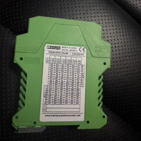
- Model Code Breakdown Explanation
| Segmento de código | Definição |
| MCR | Base series identifier: Modular Current/Voltage Converter, series of 3-way isolated signal conditioners |
| C | Dimension specification: Standard width (17.5milímetros), differs from MINI MCR series (6.2mm/12.5mm) |
| UI | Tipo de entrada: Universal Input, supports 0–10V voltage & 4–20mA current signals |
| UI | Tipo de saída: Universal Output, supports 0–10V voltage & 4–20mA current signals |
| DCI | Functional feature: DC Isolation; built-in DC/DC converter realizes 3-port isolation among Input / Saída / Fonte de energia |
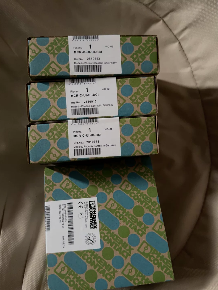
| 2810913 | Unique order number: Oficial Fênix part number for procurement & inventory management |
- Core Specification Data Sheet
2.1 Basic Electrical Specifications
| Parâmetro | Valor | Observação |
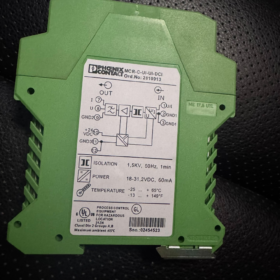
| Isolation Type | 3-way isolation (Entrada / Saída / Poder) | Withstand voltage test: In-Out:1.5kV CA; Power-Signal:1kV CA (50Hz, 60é) |
| Sinal de entrada | 0–10V DC / 4–20mA DC | Máx.. entrada:30V / 50mA |
| Sinal de saída | 0–10V DC / 4–20mA DC | Máx.. saída:15V / 30mA |
| Transmission Error | ≤0.1% FS | High-precision signal conversion |
| Fonte de energia | 18–30V CC | Nominal 24V DC; No-load current <30mA |
| Consumo de energia | ≤900mW | Under rated operating condition |
| Cut-off Frequency | 30Hz | 3dB point, effectively suppress high-frequency interference |
| Step Response | 11EM (10%–90%) | Fast signal tracking performance |
2.2 Mecânico & Especificações Ambientais
| Parâmetro | Valor | Observação |
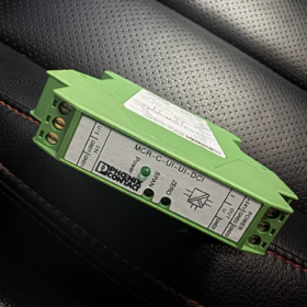
| Dimensão Geral | L17,5 mm × A99 mm × D114,5 mm | DIN rail mounting for space saving |
| Montagem | Trilho DIN padrão de 35 mm | Arbitrary installation orientation available |
| Rescisão | Terminal de parafuso plugável (COMBICON) | Comprimento de decapagem:8milímetros, M3 screw thread |
| Tamanho do cabo | Solid/Flexible:0.2–2,5 mm² (AWG24–14) | Compatible with various industrial cables |
| Temperatura operacional. | -20°C ~ +65°C | Wide temperature range for industrial environment |
| Classificação de ingresso | IP20 | Indoor cabinet installation only |
| Peso | 149.4g (com pacote) | Lightweight for easy mounting |
2.3 Certificação & Conformidade
| Certificação | Padrão | Observação |
| CE | EM 61000-6-2 / EM 61000-6-4 | EMC compliant |
| UL Recognized | UL 508 | Class I Div.2 Groups A-D; Class I Zone2 Group IIC |
| Eco-certificate | EU RoHS / RoHS da China | EFUP-50 (50-year service life for environmental compliance) |
| Código HS | 85437090 | For customs clearance in international trade |
- Full Series Part Number List (MCR-C-UI-UI-DCI Family)
| Número do pedido. | Modelo | Recurso Especial | Aplicação Típica |
| 2810913 | MCR-C-UI-UI-DCI | Versão padrão, factory preset 0–10V/0–10V | General industrial signal isolation & conversion |
| 2810939 | MCR-C-UI-UI-DCI-NC | NC = No Calibration | Fixed application without on-site calibration |
| 2811284 | MACX MCR-UI-UI | Upgraded replacement model | New generation with improved performance |
| 2810915 | MCR-C-UI-UI-450-DCI | High-load type, Máx.. output load ≤450Ω | Long-distance signal transmission & high-load occasions |
| 2810941 | MCR-C-UI-UI-450-DCI-NC | High-load without calibration | High-load fixed installation without trimming |
- Cross-reference: Obsoleto & Competitor Replacement List
4.1 Internal Phoenix Replacement
| Modelo Antigo | Modelo de substituição | Destaques de atualização |
| MCR-C-UI-UI-DCI (2810913) | MACX MCR-UI-UI (2811284) | Narrower width(12.5milímetros), lower power draw, resposta mais rápida |
| MCR-C-UI-UI-450-DCI | MACX MCR-UI-UI-450 | Identical function with compact footprint |
4.2 Comparação equivalente entre marcas
| Modelo Fênix | Equivalente de Schneider | Equivalente Siemens | Diferenças Fundamentais |
| MCR-C-UI-UI-DCI (2810913) | FOXboro IMT25 | SITRANS P DS III | Fênix:3-way isolation,1.5kV withstand, econômico |
| – | 1kV isolation,15resposta da senhora | 1.2kV isolation,12resposta da senhora | – |
- Ambiente de aplicação & Casos da Indústria
5.1 Aplicativos recomendados
- Automação Industrial: Signal isolation between PLC and field sensors/actuators to eliminate ground loop interference
- Indústria de Processos: Safe transmission of analog signals for chemical, farmacêutico, comida & beverage in explosion-proof environment
- Nova Energia: Pitch control monitoring for wind turbine, PV inverter signal acquisition, substation remote signaling renovation
- Trânsito Ferroviário: Signal isolation for train control & on-board equipment with superior EMC resistance
- Tratamento de Água: PLC automation system for municipal water plant, safe integration of process sensor signals
5.2 Aplicativos não recomendados
- Intrinsically Safe hazardous area (Select MCR-EX intrinsic safety series instead)
- Ultra-low temp (<-20°C) or ultra-high temp (>+65°C) ambiente
- Special project requiring isolation voltage higher than 1.5kV
- High-frequency signal processing above 30Hz bandwidth
5.3 Casos de aplicação típicos
Caso 1: Automotive Production Line
Aplicativo: Signal isolation for welding robot controller & pressure transmitter
Emitir: Severe EMI from welding current causes distorted sensor readings
Solução: Install MCR-C-UI-UI-DCI isolator, 1.5kV galvanic isolation, conversion error<0.1% to guarantee precise pressure control
Caso 2: Municipal Wastewater Treatment Plant
Aplicativo: Conversion & isolation between pH sensor and PLC analog input
Emitir: Different equipment ground potential drift leads to unstable output
Solução: Adopt 3-port isolation to cut ground loop; convert 0–10V sensor signal to standard 4–20mA for up to 1000m long-distance cabling
- Dicas de seleção & Regras de referência rápida
Regras de seleção rápida
- Identificação do modelo: MCR-C=standard size; UI=universal I/O; DCI=DC galvanic isolation
- Especificações principais: 3-way isolation @1.5kV, 0–10V/4–20mA, 0.1%Precisão FS,11ms step response
- Upgrade Option: Compact space saving → MACX MCR series PN:2811284
- Application Rule: Ground loop trouble →3-port isolation; long cable run →4–20mA output
- Conformidade de Remessa Aérea & CE Certification Summary
7.1 Conformidade de Transporte Aéreo
Lithium Battery Check: No built-in lithium cell, classified as non-restricted goods without special shipping marking
Classificação de Transporte: Complies with IATA DGR Class9, acceptable as general cargo
Embalagem: Original factory carton preferred; ESD bag protection recommended
7.2 CE Certification Info
Padrões Aplicáveis: EN61000-6-2 (Imunidade), EN61000-6-4 (Emissão)
DOC Download: EU Declaration of Conformity available on Phoenix official website (Doc No.:083097087_04_DoC_EU.pdf)
Valid Scope: All EU member states & regions accepting CE marking
- Guia de solução de problemas
| Sintoma de falha | Causa raiz | Remédio |
| Power LED off | 1. Missing power or reverse polarity | 1. Rewire DC supply with correct polarity |
| 2. Supply out of 18–30V range | 2. Medir & adjust input to rated 24V DC | |
| No output variation | 1. Improper input wiring | 1. Verify input wiring & tipo de sinal |
| 2. Wrong DIP switch setting | 2. Reconfigurar interruptores DIP | |
| 3. Load out of specification | 3. Voltage output ≥10kΩ; Current output ≤500Ω | |
| Fluctuating output | 1. Input signal interfered | 1. Single-point grounding for shield cable |
| 2. Ondulação excessiva da fonte de alimentação | 2. Add power filter | |
| 3. Poor module earthing | 3. Secure module chassis ground | |
| Excessive conversion error | 1. Zero/Span drift | 1. Re-trim Zero & Span (±2% adjustable) |
| 2. Ambient temp out of rated range | 2. Improve cabinet ventilation | |
| 3. Mismatched load impedance | 3. Adjust load to specified range |
Phoenix MCR‑C‑UI‑UI‑DCI (2810913) On-site Installation Manual
- Safety Precaution (Mandatory Reading)
Classe de Proteção: IP20, indoor dry cabinet installation only
Suportar Tensão: In-Out 1.5kV AC/60s; Power-Signal 1kV AC/60s, overvoltage withstand test prohibited
Proteção ESD: Static-sensitive component; discharge body static by touching grounded metal before handling
Hazardous Area: Suitable for Zone2 / Class I Div.2 only; MCR‑EX IS series for Intrinsically Safe location
Fonte de energia:18–30V CC (Nominal 24V DC); reverse polarity will permanently damage unit, confirm polarity prior to power-up
- Unpacking & Inspeção
2.1 Packing List
Isolation amplifier MCR‑C‑UI‑UI‑DCI (2810913) ×1
This installation manual ×1
Factory test certificate ×1
2.2 Visual Check
No housing crack, intact snap latch, non-deformed & rust-free terminals
Confirm model & part No.: MCR‑C‑UI‑UI‑DCI / 2810913
- Ambiente de instalação & Clearance Requirement
3.1 Condição Ambiental
Temperatura operacional: -20°C ~ +65°C
Temperatura de armazenamento: -25°C ~ +70°C
Umidade:10%~90% non-condensing
Min.30cm clearance away from strong EMI source (VFD, large motor, transformador)
3.2 Espaçamento de montagem
Montar: Trilho DIN padrão de 35 mm (EN60715), any mounting direction allowed
Side gap between adjacent modules ≥5mm
Vertical top/bottom clearance ≥20mm for heat dissipation & manutenção
Install at upper/middle cabinet position; avoid dusty bottom compartment
- Montagem em trilho DIN & Dismount Steps
4.1 Montagem
- Clean DIN rail from grease & burr, ensure reliable rail grounding
- Flip upward the orange top latch of module
- Hook upper notch onto top edge of DIN rail then press down module bottom
- Audible click sound confirms locked & fixed without wobble
4.2 Dismounting
- Cut off module power & all field signals first; no live removal allowed
- Lift orange release latch upward
- Lift module bottom upward to detach from DIN rail then take out
- Definição de terminal & Especificação de fiação
5.1 Terminal Pinout (Left to Right)
| Pino Não. | Marcação | Definição | Observação |
| 1.1 | IN U | Entrada de Tensão (0–10V) | Signal Positive |
| 1.2 | IN I | Entrada atual (4–20mA) | Signal Positive |
| 1.3 | GND 1 | Input Common | Signal Negative |
| 2.1 | OUT U | Saída de tensão (0–10V) | Signal Positive |
| 2.2 | OUT I | Saída atual (4–20mA) | Signal Positive |
| 2.3 | GND 2 | Output Common | Signal Negative |
| 3.1 | 24Em DC | Poder Positivo | 18–30V CC |
| 3.2 | GND | Poder Negativo | Supply Ground |
5.2 Padrão de fiação
Cable strip length:8milímetros (too long → short circuit; too short → poor contact)
Tamanho do condutor: Solid/Flexible 0.2–2.5mm² (AWG24–14); ferrules required for stranded flexible wire
Screw torque:0.5~0.6N·m for M3 terminal, avoid over-tightening thread slip
Shield cable: Single-end cabinet grounding (transmitter end floating) to eliminate ground loop
5.3 Typical Wiring Examples
Ex1: 4–20mA Input →4–20mA Output (2-wire transmitter)
Transmitter + →1.2(IN I)
Transmitter − →1.3(GND1)
2.2(OUT I) →PLC AI+
2.3(GND2) →PLC AI−
3.1→24V DC+;3.2→24V DC−
Ex2:0–10V Input→0–10V Output (Voltage sensor)
Sensor +→1.1(IN U)
Sensor −→1.3(GND1)
2.1(OUT U)→PLC AI+
2.3(GND2)→PLC AI−
3.1→24V DC+;3.2→24V DC−
- DIP Switch Configuration (Factory preset for 2810913:0–10V/0–10V)
6.1 Switch Location (Side housing; remove cover to access)
S1: Configuração de entrada
S1‑1:OFF=0–10V; ON=4–20mA
S1‑2:OFF=Unipolar; ON=Bipolar(±5V/±10V)
S2: Configuração de saída
S2‑1:OFF=0–10V; ON=4–20mA
S2‑2:OFF=Unipolar; ON=Bipolar(±5V/±10V)
6.2 Factory Default (2810913)
S1:OFF/OFF (Unipolar 0–10V Input)
S2:OFF/OFF (Unipolar 0–10V Output)
6.3 Setting Procedure
- Cut off power supply then remove 2 cross-head screws to open cover
- Toggle DIP switches as required with fully seated position
- Refit housing & tighten screws before power-on test
- Power-up & Comissionamento
7.1 Inspeção Pré-energia (Obrigatório)
Full wiring check: No cross-connection, short circuit or loose terminal
DC supply test: 24V DC ±10% measured across pin3.1 &3.2
Isolation test: No continuity between Input/Output/Power with multimeter continuity mode
7.2 Indicação de status LED
PWR(Verde): Steady ON=Normal Supply; OFF=Power fault/reverse polarity
CORRER(Verde): Blinking=Running normally; Solid/OFF=Module malfunction
7.3 Calibração (Optional for high precision requirement)
Zero Adjustment: Feed zero input signal, trim ZERO potentiometer for zero output
Span Adjustment: Feed full-scale input, trim SPAN potentiometer for full-scale output
Precisão: ≤0.1%FS, max temperature drift ≤±2%
- On-site Quick Troubleshooting
8.1 Power LED Dark
Causa: Reverse polarity, abnormal voltage, fiação solta | Ação: Correct polarity, measure voltage, retighten terminals
8.2 Sinal de saída zero
Causa: Fiação errada, mismatched DIP setting, sobrecarga | Ação: Religar, reset switches, check load impedance
8.3 Unstable Swinging Output
Causa: Improper shield grounding, high supply ripple, nearby EMI | Ação: Single-point ground, install power filter, relocate away from interference source
8.4 Out-of-spec Accuracy
Causa: Thermal drift, zero/span shift, mismatched load | Ação: Recalibrar, improve ventilation, adjust load
- Manutenção Periódica
Every 6-month routine: Power off to clean terminal/housing, recheck screw torque & recalibrate accuracy
Forbidden operation: Hot plug/unplug, overvoltage/overtemperature running, unauthorized internal circuit disassembly
- Suporte Técnico & Parte Alternativa
Manufacturer Support: Phoenix Contact China
Substituição de atualização: MACX MCR‑UI‑UI (2811284):12.5mm largura, menor consumo de energia, faster response speed


")


")


")
NH42-63-318x560.png "Chaves de transferência automática tipo PC CHINT (ATS)NH42-63/4SZ")


