 Contator,disjuntor,sensor,Codificador,CLP,Conversor

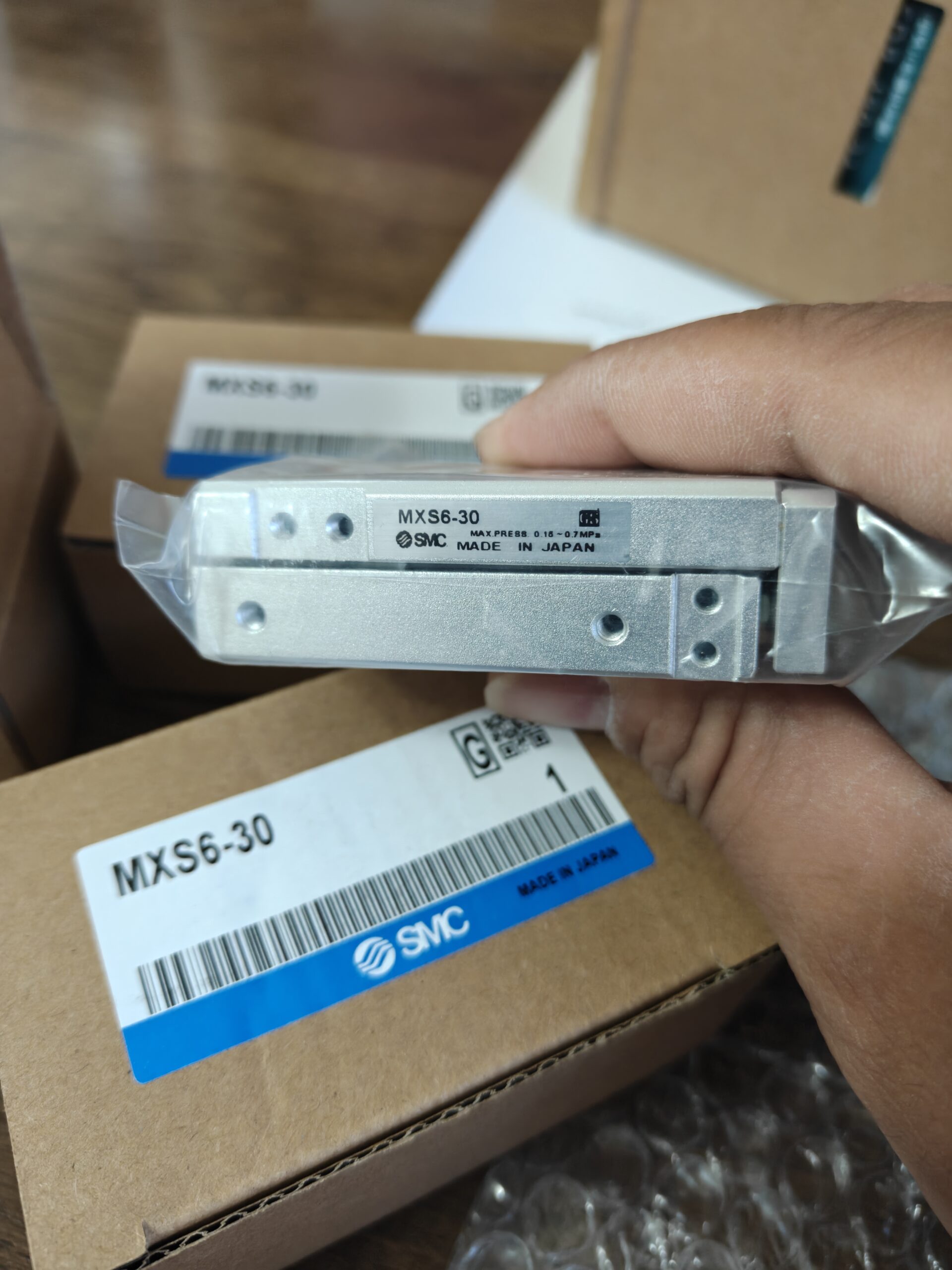

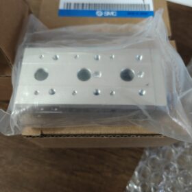
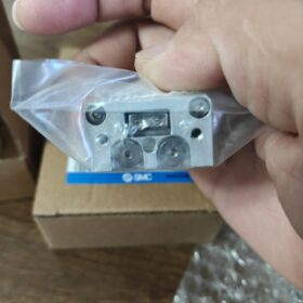
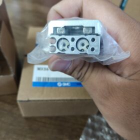
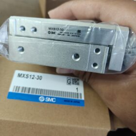
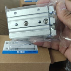
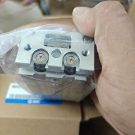
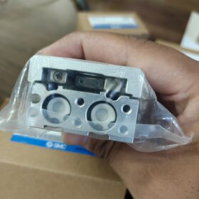
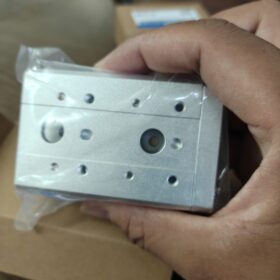
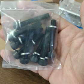
MXS: Mesa deslizante pneumática de cilindro duplo com guia de rolos cruzados; Furo 6mm, Curso 30mm, tipo padrão, dupla ação, ímã embutido, amortecedores de borracha em ambas as extremidades
- Explicação do código do modelo
MXS6-30
MXS: SMC série de mesa deslizante de ar (guia de rolo cruzado, construção de dois cilindros)
6: Tamanho do furo φ6mm (estrutura de dois cilindros)
30: Curso padrão 30mm
Extensões de sufixo comuns:
COMO: Ajustador de curso frontal; Bobagem: Ajustador de curso traseiro; NO: Ajustador de curso de extremidade dupla
B: Amortecedor hidráulico; eu: Corpo de imagem espelhada
–M9BW/-A93: Sensores automáticos instalados de fábrica
- Especificações Técnicas Principais
| Item | Parâmetro |
| Ação | Dupla ação |
| AVC | 30 milímetros, tolerância de curso 0~+1mm |
| Pressão Operacional | 0.15-0,7 MPa; Pressão de prova 1,05 MPa |
| Rosca da porta | M3×0,5 |
| Almofada | Amortecedores de borracha padrão (amortecedor hidráulico opcional-B) |
| Faixa de velocidade do pistão | 50-500 mm/s |
| Lubrificação | Não lubrificante |
| Temperatura ambiente | -10~+60°C (sem glacê) |
| Ímã embutido | Sim, compatível com interruptores automáticos |
| Impulso Teórico @0,5MPa | Estender 27N, Retrair 21N |
Peso: aprox.. 0.22 kg; Otimizado para montagem horizontal, adequado para transferência precisa de curso curto, posicionamento e atuação do gabarito.
- Destaques de montagem
- Montagem em três lados: Principal, opções de montagem inferior e lateral. Rosca lateral M2,5×0,45. Evite torque excessivo e profundidade excessiva do parafuso para evitar deformação e travamento da guia.
- Furos roscados na mesa de trabalho M4 para montagem de peças/acessórios.
- A carga admissível é governada pelo momento e pelo comprimento do balanço, não só impulso. O balanço mais longo reduz a carga permitida.
- Interruptores automáticos compatíveis: D-M9B/M9N/A93/Z73. Os interruptores são instalados nos slots T do corpo; interruptores permanecem parados (não viaje com mesa deslizante).
- Exemplos comuns de modelos completos
MXS6-30AS: Curso frontal ajustável (0-5 faixa de ajuste mm)
MXS6-30BS: Curso traseiro ajustável
MXS6-30AT: Ambas as extremidades ajustáveis
MXS6-30B: Amortecedores hidráulicos de extremidade dupla para impacto reduzido
MXS6-30-M9BW: Pré-equipado com dois detectores automáticos M9BW
- Substituições Domésticas (Pegada de montagem idêntica)
ártico: HLQ6-30;Quélica: MDX6-30;Mecânica direta intercambiável.
- Usado / Lista de verificação de inspeção de unidades usadas
- Forneça ar a 0,3-0,4 MPa; operação suave de deslocamento total sem travar ou rastejar.
- Inspecione os amortecedores de borracha quanto a rachaduras e envelhecimento.
- Verifique a folga lateral da mesa de trabalho: Folga lateral excessiva indica guia de rolos cruzados desgastada.
- Teste de ar em curso completo; sem vazamento de ar interno ou externo.
- Verifique a integridade do ímã integrado: A chave automática deve produzir um sinal válido em ambas as posições de fim de curso.
- Aplicações Típicas
Equipamentos de automação de pequena escala, montagem eletrônica, gabarito push-pull, mecanismo de classificação, posicionamento de transferência em miniatura.
Casos práticos de aplicação SMC MXS6-30
MXS6-30 é um furo de φ6mm, 30 Mesa deslizante pneumática com curso de mm com guia de rolos cruzados. O tamanho compacto e a boa capacidade de resistência ao momento tornam-no ideal para movimento alternativo de carga leve e curso curto. Carga horizontal máxima permitida: aprox.. 0.6 kg. Amplamente utilizado em eletrônica, bateria de íon de lítio, inspeção e pequenas máquinas de automação personalizadas.
Caso1: Pick-and-place de componentes eletrônicos (Máquina de montagem de eletrônicos de consumo)
Condição Operacional: Equipado com pinça pneumática miniatura. 30 O movimento alternativo horizontal de mm transfere pequenos componentes de PCB do alimentador para o gabarito de posicionamento. Tempo de ciclo:1.2-2 s/ciclo, carregar 150-250g.
Modelo Selecionado: MXS6-30-M9BW, feedback de posição do comutador automático de extremidade dupla.
Notas de projeto: Minimize a saliência. Instale válvulas de controle de fluxo para definir a velocidade de 150-250 mm/s para reduzir o impacto. Monte a pinça diretamente na mesa de trabalho; corpo fixado pela parte inferior.
Por que MXS6-30: Rigidez lateral superior em comparação com a série MXS-U. Repetibilidade estável para reciprocidade. Alternativa que economiza espaço aos servomódulos para redução de custos.
Caso2: Câmera / Posicionamento de alimentação do sensor (Equipamento de inspeção visual)
Condição Operacional: Aciona uma câmera industrial ou sensor a laser para deslocamento para frente e para trás de 30 mm para inspecionar peças de trabalho de espessura variável. Imagem estacionária na posição alvo, ciclismo de baixa frequência.
Modelo Selecionado: MXS6-30AS (ajustador de curso frontal, 0-5 mm ajuste fino para distância de inspeção).
Notas: Evite longos balanços; monte a carga perto da superfície da mesa de trabalho. Estabilize a pressão do ar fornecido para minimizar o desvio de posição causado pela flutuação de pressão.
Uso da Indústria: Inspeção da aparência do conector, máquinas de classificação de peças de plástico.
Caso3: Parada de gabarito / Posicionamento da peça (Linha transportadora)
Condição Operacional: Parar e pré-posicionar peças de trabalho no transportador. O slide se estende para bloquear a peça de trabalho; retrai para liberação após inspeção. 30 O curso de mm fornece função parar e limpar.
Modelo Selecionado: MXS6-30 padrão com detectores automáticos D-A93.
Montagem: Montagem na parede lateral para economizar altura vertical da máquina.
Observação: Somente para parada de peças leves. Não é possível sustentar um impacto forte; adicione bloco de pára-choques dedicado para cenários de alto impacto.
Caso4: Mini-ajuste à pressão & inserção do conector (Equipamento de montagem de conectores)
Condição Operacional: Pré-impressão leve para pequenos conectores e circuitos flexíveis FPC. O slide se estende para pré-compressão e retrai para retração. Empuxo de extensão teórico 27N @0,5MPa; adequado apenas para prensagem com força leve, não são tarefas pesadas de ajuste à pressão.
Modelo Selecionado: MXS6-30B (amortecedor hidráulico) para ciclos de alto impacto para proteger conectores delicados.
Lembretes: Se for necessária uma força de pressão maior, atualizar para MXS8-30.
Caso 5: Célula de íon de lítio de pequeno formato / mecanismo de classificação de eletrodos
Condição Operacional: Desvio qualificado / Células soft-pack miniatura NG em compartimentos diferentes por meio de pressão horizontal de 30 mm.
Modelo Selecionado: MXS6-30-M9N, design sem lubrificação para ambiente de fábrica de baterias com pouca névoa de óleo.
Restrições: Carregar ≤300g. O balanço longo acelerará o desgaste da guia.
Caso 6: Cartão de reagente / Impulso de tiras de teste para equipamentos compactos de diagnóstico médico
Condição Operacional: Posicione cartões de reagentes e tiras de teste em ambiente limpo de carga leve. A operação sem lubrificação elimina o risco de contaminação por névoa de óleo.
Modelo Selecionado: MXS6-30 padrão com ímã integrado e detectores automáticos de estado sólido.
Observação: Instale removedor de névoa de óleo na linha de ar para qualidade do ar de nível médico.
Caso7: Eixo único para pórtico XY (Plataforma de transferência compacta de 2 eixos)
Condição Operacional: MXS6-30 como eixo X empilhado sobre a segunda mesa deslizante para simples coleta e posicionamento pneumático XY.
Notas: A massa total do conjunto do eixo superior mais a peça de trabalho não deve exceder a carga permitida do eixo inferior. Evite grandes saliências.
⚠️ Armadilhas comuns para seleção MXS6-30
- Carga horizontal máxima permitida 0,6 kg. A carga permitida diminui drasticamente com balanços mais longos. Capacidade de momento, não impulso bruto, é o principal fator limitante.
- 30 mm é o curso ideal para furo 6. A rigidez degrada significativamente no acidente vascular cerebral >40 milímetros.
- Para aplicações cíclicas de alta frequência e propensas a impactos, escolha a variante de amortecedor hidráulico -B; amortecedores de borracha padrão degradam-se rapidamente sob operação contínua em alta velocidade.
- MXS6-30 versus MXQ6-30: MXS usa guia de rolos cruzados com resistência superior ao momento. MXQ usa guia de rolamento de esferas para menor atrito, mas desempenho antimomento mais fraco, adequado para tarefas com cargas ultraleves.
Instruções completas de montagem SMC MXS6-30
MXS6-30 suporta montagem inferior, montagem lateral e montagem superior. Mesa de trabalho para montagem de peças; corpo principal fixado à estrutura da máquina.
- Especificações de rosca & Torques de aperto (Especificação de fábrica SMC)
- Montagem do corpo (fixar o corpo do cilindro na estrutura da máquina)
Roscas de montagem laterais: M2,5×0,45, Torque máximo de aperto 0,5N·m, Profundidade máxima de inserção do parafuso 3,5 mm
⚠️Parafusos com comprimento excessivo comprimirão o conjunto da guia interna e causarão emperramento ou danos permanentes!
Roscas de montagem inferior: M2,5×0,45, Torque máximo 0,5N·m
- Mesa de trabalho (acessório de montagem / peça de trabalho)
Furos roscados de mesa: M4×0,7, Torque máximo de aperto 1,2N·m
A mesa de trabalho está movendo o conjunto da guia de rolos cruzados. Nunca aplique torque excessivo.
- Rosca da porta aérea
Porta: M3×0,5, compatível com acessórios pneumáticos em miniatura.
Importante: Parafusos M2.5 requerem baixo valor de torque. Chave de torque recomendada; não confie na sensação das mãos.
- Quatro configurações de montagem
1) Montagem inferior (Mais comum, orientação horizontal)
Aperte os parafusos para cima através dos furos roscados na parte inferior do corpo. Deslize a mesa voltada para cima, reciprocidade horizontal.
Aplicativo: Transferir, empurrar-puxar, alimentação de visão.
Vantagem: Melhor condição de carregamento, capacidade máxima de carga permitida.
Observação: Profundidade de inserção do parafuso ≤3,5 mm. Não entre em contato com os componentes internos da guia.
2) Montagem lateral (Instalação lateral na parede)
Fixe nos furos roscados laterais do corpo. A mesa deslizante executa movimento horizontal enquanto a unidade fica de lado.
Aplicativo: Mecanismos de parada da linha transportadora, layout de máquina com altura limitada.
A montagem lateral aumenta o momento aplicado. Reduzir a carga permitida. Monte as peças de trabalho o mais próximo possível da superfície da mesa.
3) Montagem superior (Despesas gerais / montagem invertida)
Prenda o corpo por cima. Cilindro pendurado de cabeça para baixo; mesa de trabalho se move para baixo.
Montagem invertida: O peso da peça carrega totalmente o sistema de guia. A carga deve ser reduzida. Não é adequado para operação de alto ciclo e alta velocidade.
4) Montagem em eixo vertical (Movimento de cima para baixo)
Deslocamento do slide orientado verticalmente. A mesa de trabalho se move para cima e para baixo.
❗Risco: O peso da peça altera diretamente o desempenho do amortecimento. Válvulas de controle de fluxo obrigatórias para operação em baixa velocidade. Não para cargas pesadas. Carga útil de montagem vertical recomendada ≤150g.
- Instalação de troca automática
- Interruptores automáticos (D-M9BW / D-A93) instale em ranhuras T em ambos os lados do corpo estacionário, não na mesa de trabalho móvel.
- Afrouxe o parafuso de fixação da ranhura, deslize o interruptor automático para a posição desejada do gatilho, reapertar.
- Slots em T disponíveis em ambos os lados; 1 ou 2 detectores automáticos podem ser instalados.
- Procedimento de montagem
- Pré-aperte todos os parafusos de montagem no corpo primeiro, em seguida, aperte progressivamente cada parafuso até o valor especificado. Não aperte totalmente um parafuso antes dos outros, para evitar distorção do corpo.
- Monte a peça de trabalho na mesa de trabalho através de parafusos M4, observe os limites de torque.
- Teste de ar a 0,3-0,4 MPa para operação suave em curso completo sem travamento.
Se ocorrer bloqueio: Quase sempre causado por parafusos inseridos muito profundamente, comprimindo a guia de rolos cruzados; reduzir a profundidade de inserção do parafuso.
- Instale acessórios de controle de fluxo; definir a velocidade do pistão para não exceder 500 mm/s.
- Ajuste as posições da chave automática e confirme a integridade do sinal de fim de curso.
- Proibições críticas de montagem (Fontes de falhas frequentes)
- A profundidade de inserção do parafuso nunca deve exceder 3,5 mm. Parafusos M2.5 com comprimento excessivo destruirão o conjunto da guia.
- Não aplique lateralmente / forças externas transversais à mesa de trabalho; evite carregar o slide com choque.
- Nunca bata no corpo ou na mesa de trabalho após a instalação; a pré-carga do rolo cruzado será perdida, criando reação.
- Aplicações de montagem vertical: O peso da peça prejudica o desempenho do amortecedor de borracha. Selecione o modelo de amortecedor hidráulico -B para ciclismo vertical frequente.
- Não especifique a carga apenas pela classificação de empuxo; calcular momento aplicado. Momento máximo permitido para MXS6-30: 1.2 N·m.
- Montagem multieixo empilhada (Plataforma XY)





NH42-63-318x560.png "Chaves de transferência automática tipo PC CHINT (ATS)NH42-63/4SZ")



