 Contactor,întrerupător de circuit,senzor,Codificator,PLC,Convertor

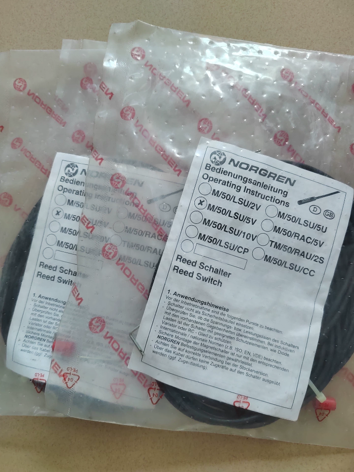

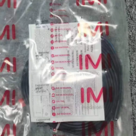
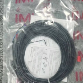
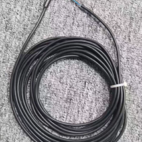
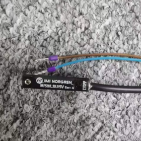
Defalcarea modelului
M/50: Seria de produse, comutator de proximitate magnetic cilindric
LSU: Tip stuf, Deschis normal (NU), cu indicator LED, priza de cablu
5: Lungimea cablului 5 metri
V: Versiune universală cu tensiune largă (10~170V AC/DC)
Aplicația de bază
Detectează poziția de cursă completă a pistoanelor cilindrului pneumatic (semnale de poziție extins/retras pentru feedback la PLC-uri sau relee)
- Specificații electrice de bază
| Parametru | Caietul de sarcini |
| Principiul de funcționare | Contact cu stuf (actionare mecanica magnetica) |
| Configurare contact | Deschis normal (NU): deschis fără magnet, închis lângă inelul magnetic |
| Tensiune de operare | 10~170 V AC/DC; compatibil cu sistemele generale de 240 V AC/DC |
| Curent de comutare maxim | 0.18 O |
| Putere de comutare maximă | 10 W |
| Timp de răspuns | 1.8 Domnișoară |
| Indicator luminos | LED galben încorporat, iluminat la acţionarea magnetică |
| Protecție la intrare | IP66 (rezistent la praf, protejat împotriva pulverizării de înaltă presiune) |
| Temperatura de operare | -20 ℃ la +80 ℃ |
| Specificația cablului | 5m cablu PVC, 2-miez 0,25 mm² |
| Standarde de conformitate | ÎN 60947-5-2, RoHS, AJUNGE |
| Origine | Polonia |
- Mecanic & Instalare
3.1 Cilindri compatibili
Cilindri profil Norgren RA/8000 și KA/8000; suporturi de montare inel/clemă potrivite (Seria QM/33), compatibil cu dimensiunile alezajului 10/20/25/32/40/50/63/80/100mm.
3.2 Metode de montare
Cilindri profil T-slot: Glisați comutatorul direct în fanta în T a cilindrului, nu sunt necesare paranteze suplimentare
Cilindri cu tirant rotunzi: Fixat prin suporturi de cleme metalice opționale
3.3 Materialul carcasei
Plastic de inginerie, rezistent la contaminarea cu ulei și vibrațiile industriale
- Ghid de selecție între serii (Diferențiere rapidă)
- M/50/LSU/2V: 2-cablu metru, toți ceilalți parametri identici cu varianta 5V
- M/50/LSU/5U: 5-cablu metru, model DC de joasă tensiune (10~30VDC)
- Seria M/50/EHP: Electronic cu stare solidă fără contact (PNP/NPN), înlocuitor de înaltă frecvență de lungă durată pentru întrerupătoarele cu lame
- Scenarii de aplicare
Linii de asamblare automate, utilaje de ambalare, dispozitive pneumatice pentru mașini-unelte
Detectare limită de cursă pentru cilindrii de manipulare a materialelor, detectarea poziției pentru cilindrii echipamentelor de ștanțare
Feedback de poziție pentru actuatoarele pneumatice generale, compatibil cu dulapuri de control AC/DC
- Precauții de funcționare
- Contactele Reed nu pot conduce sarcini grele; pentru transferul semnalului trebuie folosit un releu de interpunere. Acționarea directă a bobinelor solenoidelor este interzisă.
- Evitați mediile cu câmpuri magnetice puternice sau interferențe electromagnetice puternice din partea echipamentelor de sudură pentru a preveni declanșarea falsă.
- Raza de îndoire minimă a cablului ≥ 10× diametrul exterior al cablului; protecția tubului ondulat recomandată pentru echipamentele cu vibrații continue.
- Înlocuiți cu comutatoare electronice M/50 în stare solidă dacă temperatura mediului depășește 80℃.
- Numerele piesei pentru accesorii potrivite
Suport de prindere pentru alezaj Ø20: QM/33/020/22
Suport de prindere pentru alezaj Ø32: QM/33/432/22
Clip de fixare a comutatorului rapid: QM/27/2/1
Întrerupător magnetic IMI Norgren M/50/LSU/5V Reed Manual complet de instalare
Informații de bază ale documentului
Model: M/50/LSU/5V (M50LSU5V)
Tip de produs: Comutator de poziție magnetic normal deschis, LED galben încorporat, 5m cablu cu 2 fire, tensiune largă 10~170V AC/DC
Cilindri compatibili: Norgren RA/8000 & Cilindri cu profil cu fantă în T seria KA/8000, cilindri cu tirant rotunzi
Protecție la intrare: IP66
Standarde: ÎN 60947-5-2, RoHS, AJUNGE
Cuprins
- Inspecție de despachetare & Verificarea modelului
- Instalare mecanică (Două soluții: Profil T-Slot / Cilindri cu tirant rotund)
- Lista de selecție pentru suporturi de montare potrivite
- Specificații cablare electrică & Scheme de cablare
- Proceduri de punere în funcțiune
- de mediu & Interdicții de instalare (Restricții critice)
- Matricea de depanare
- Întreținere de rutină
- Specificații tehnice de referință rapidă
1 Inspecție de despachetare & Verificarea modelului
1.1 Inspecția mărfurilor primite
- Verificați modelul gravat cu laser pe corpul comutatorului: M/50/LSU/5V; confirmați lungimea cablului de 5 metri
- Inspectați carcasa pentru fisuri, rădăcina cablului pentru deteriorare, fereastra de vizualizare LED intactă
- Accesorii: Surub de fixare preinstalat pe unitate; consolele de prindere trebuie comandate separat pentru cilindrii rotunzi
1.2 Definirea segmentului de model
M/50: Seria de comutatoare de proximitate magnetice
L: Echipat cu indicator LED
Sunt: Stuf de uz general Normal deschis, tip priză cablu
5: 5-metru lungimea cablului
V: Model universal de tensiune largă, 10~170V AC/DC
2 Ghid de operare pentru instalarea mecanică
2.1 Cilindri cu profil T-Slot (Seria Norgren RA/KA, Montaj recomandat)
- Slăbiți șurubul de fixare cu cap plat de la coada comutatorului și deschideți fanta pentru cleme
- Introduceți complet clema comutatorului în fanta în T din partea cilindrului, glisați în poziția de detectare a țintei (poziţia magnetului la extensia/retragerea completă a cilindrului)
- Reglați fin poziția orizontală: Punct de declanșare optim atunci când LED-ul galben rămâne aprins constant pe măsură ce magnetul pistonului trece comutatorul
- Strângeți șurubul de fixare a cozii cu o șurubelniță plată, cuplu 0,8~1,0 N·m pentru a preveni deplasarea de la vibrații
- Dirijați ieșirea cablului în jos sau în lateral; dirijarea în sus este interzisă pentru a evita acumularea de apă
2.2 Cilindri cu tirant rotund (Fără slot în T, Montarea suportului de clemă)
- Selectați clema metalică din seria QM/33 potrivită pentru dimensiunea alezajului cilindrului
- Montați clema pe cilindrul, pre-strângeți șuruburile de prindere și glisați în poziția de detectare
- Fixați comutatorul M/50 în dispozitivul de prindere integrat, fixați șurubul de fixare a comutatorului
- Strângeți complet clema pentru a preveni alunecarea în timpul funcționării; cuplu de strângere 1,2~1,5 N·m
2.3 Standarde de poziție de montare
Fața de detectare aliniată cu peretele exterior al cilindrului, clearance-ul zero, fără strat intermediar metalic
Distanță de minim 20 mm între două întrerupătoare dintr-un cilindru pentru a evita interferența magnetică reciprocă
Feriți-vă de inserțiile magnetice puternice de pe capacele cilindrului (magneți tampon)
3 Lista de numere de piesă a suportului de montare potrivit
| Accesoriu Nr. | Aplicație | Dimensiunea alezajului compatibilă |
| QM/27/2/1 | Clip universal pentru cilindri profil (clemă identică premontată pentru comutator) | Toți cilindrii cu fantă în T |
| QM/33/010/22 | Clema din aluminiu pentru cilindri rotunzi | Ø10 |
| QM/33/020/22 | Clema din aluminiu pentru cilindri rotunzi | Ø20/25 |
| QM/33/432/22 | Clema din aluminiu pentru cilindri rotunzi | Ø32/40 |
| QM/33/463/22 | Clema din aluminiu pentru cilindri rotunzi | Ø50/63/80/100 |
4 Specificații cablare electrică (Capitolul de bază)
4.1 Definiția cablului (2-miez cablu PVC, 0.25mm²)
Sârmă maro (BN): Putere pozitivă / Linie de curent alternativ
Sârmă albastră (ACEST): Putere negativă / Linie neutră AC
Reed intern Contactele normal deschise închid circuitul când inelul magnetic se apropie, LED-ul galben se aprinde
4.2 Două scheme standard de cablare
Schema A: Intrare digitală PLC Drive (Cele mai comune)
- Sistem DC24V: BN conectat la +24V, BN conectat la terminalul de intrare PLC, Terminal comun PLC conectat la 0V
- Sistem AC220V: BN conectat la Live (L), BU conectat la Neutru (N) al modulului de intrare AC PLC
> AVERTIZARE: Curentul maxim de comutare al contactelor reed este de 0,18 A; acționarea directă a bobinelor solenoidelor este strict interzisă!
Schema B: Releu de interpunere pentru transferul sarcinilor grele
- Bobina releului cablată în serie cu BN & BU merge în jur
- Contactele releului controlează sarcinile cu curent ridicat, inclusiv supapele solenoide și luminile indicatoare
4.3 Restricții critice de cablare
- Fără alimentare în condiții de gol (Circuitul fără sarcină arde instantaneu contactele de lame prin arc electric)
- Separați cablurile de semnal de cablurile de alimentare (invertoare, cablurile motorului), distanță minimă de 10 cm pentru a evita declanșarea falsă indusă de interferențe
- Raza de îndoire minimă a cablului ≥10× diametrul exterior al cablului; îndoirea/tragerea repetată de rădăcina cablului este interzisă
- Izolați alimentarea completă a dulapului înainte de lucrările de cablare pentru a evita șocurile electrice și arderea contactelor
4.4 Protecție pentru rutarea cablurilor
Echipament vibrator: Dirijați cablurile prin tubulatura ondulată; rezervați 5 ~ 8 cm slăbiciune la rădăcina cablului comutatorului
Ceață de ulei & medii de pulverizare: Înfășurați îmbinările cablurilor cu bandă impermeabilă; sigilați punctele de intrare ale cablurilor în interiorul dulapurilor de comandă
5 Proceduri standard de punere în funcțiune a unității complete
Pas 1 Calibrarea poziției mecanice
Acționați manual pistonul cilindrului pentru a glisa încet magnetul încorporat peste zona de detectare a comutatorului
Magnet la poziția de detectare: LED-ul galben rămâne aprins continuu
Magnetul departe de poziția de detectare: LED-ul complet stins
Dacă LED-ul pâlpâie, Comutator de reglare fină în poziție orizontală pentru declanșare stabilă fără stroboscop
Pas 2 Testarea semnalului electric
- Porniți, Măsurați continuitatea circuitului prin multimetru conectat în serie
- Magnet în zona de detectare: Circuit închis (rezistență aproape de 0Ω)
- Magnet departe de zona de detectare: Circuit deschis (rezistență infinită)
Pas 3 Verificare automată a ciclului
Rulați ciclul alternativ al cilindrului 10 ori în gol; confirmați semnalul de ieșire stabil la fiecare sfârșit de cursă fără pierdere de semnal sau declanșare falsă
6 de mediu & Interdicții de instalare (Operațiuni interzise)
- Limită de temperatură: Interval de funcționare -20℃ ~ +80℃; înlocuiți cu comutatoare electronice M/50 peste 80℃
- Interferență magnetică: Țineți departe de echipamentele de sudură, magneți permanenți puternici, servomotoare, cablurile de ieșire ale invertorului pentru a preveni funcționarea falsă
- Protecție la impact: Interziceți lovirea sau scăparea unității de comutare; tubul din stuf din sticlă se rupe cu ușurință la impact
- Medii chimice: Instalați capace de protecție în acid puternic, medii alcaline sau cu solvenți cu concentrație mare; carcasa din plastic se va coroda și se va crăpa
- Spălare sub presiune: Clasamentul IP66 rezistă doar la pulverizare de joasă presiune; Jetul direct de apă de înaltă presiune la rădăcina cablului cauzează pătrunderea apei și defectarea unității
- Operație supraîncărcată: Puterea de comutare nu trebuie să depășească 10W; releu de interpunere obligatoriu pentru sarcini de putere mai mare
7 Matricea de depanare
| Simptom de eroare | Cauza de bază | Acțiuni de remediere în pas |
| LED stins, nici un semnal când magnetul ajunge la punctul de detectare | 1. Cablaj rupt/inversat | 1. Tai puterea, sertizează din nou bornele și verifică cablajul maro/albastru |
| 2. Montare întrerupător slăbit/deplasat | 2. Strângeți șurubul de fixare și recalibrați poziția | |
| 3. Deteriorări interne ale stufului | 3. Înlocuiți cu o unitate nouă M/50/LSU/5V | |
| LED pâlpâit, pierdere intermitentă a semnalului | 1. Distanță excesivă între comutator și magnet | 1. Montați comutatorul la nivel de peretele cilindrului pentru a elimina spațiul liber |
| 2. Interferențe electromagnetice severe | 2. Dirijați cablurile de semnal separat și adăugați ecranare | |
| 3. Rupere internă a firului la rădăcina cablului | 3. Tăiați segmentul de cablu deteriorat și re-terminați | |
| Comutatorul se arde imediat după pornire | 1. Acționarea directă a sarcinilor solenoide mari | 1. Instalați releul de interpunere pentru transferul sarcinii |
| 2. Tensiune de intrare peste 170V | 2. Potriviți tensiunea sistemului și adăugați regulatorul de tensiune | |
| 3. Activare în scurtcircuit fără sarcină | 3. Sarcina de serie trebuie montată înainte de punerea sub tensiune a circuitului | |
| Comutator glisiere din poziție în timpul funcționării cilindrului | Cuplu de strângere a șuruburilor insuficient, slăbirea de la vibrații | Strângeți din nou șurubul de fixare la 0,8~1 N路m; adăugați șaibe anti-slăbire pentru mașinile cu vibrații mari |
8 Specificații de întreținere de rutină
- Inspecție zilnică: Verificați starea declanșării LED-ului, inspectați cablurile pentru uzură sau crăpare
- Întreținere săptămânală: Curățați uleiul și praful de pe suprafața comutatorului; previne aderența resturilor metalice la carcasă
- Inspecție lunară: Strângeți șuruburile de fixare pentru a evita slăbirea din cauza vibrațiilor pe termen lung
- Calibrare semianuală: Verificați stabilitatea semnalului; întreține unități de schimb de rezervă pentru linia de producție în masă
9 Specificații tehnice de bază ale produsului (Referință de instalare)
| Parametru | Specificație M/50/LSU/5V |
| Element Senzor | Tub de stuf, Deschis normal (NU) |
| Tensiune de operare | 10~170V AC/DC |
| Curent de comutare maxim | 0.18O |
| Putere de comutare maximă | 10W |
| Timp de răspuns | 1.8Domnișoară |
| Indicator luminos | LED galben, iluminat când este închis |
| Specificația cablului | 5m, 2×0,25 mm² PVC |
| Protecție la intrare | IP66 |
| Temperatura de operare | -20℃ ~ +80℃ |
| Materialul carcasei | Plastic de inginerie ignifug |
| Standard de conformitate | ÎN 60947-5-2 |
Defecte comune, Cauze & Soluții de remediere pentru Norgren M/50/LSU/5V (M50LSU5V) Comutator magnetic
Acest întrerupător magnetic cu contact cu lame are patru categorii principale de defecțiuni: fara semnal de iesire, semnal pâlpâit, corpul comutatorului ars, schimbare mecanică. Deficiențe inerente ale comutatorului cu lame (susceptibil la curent ridicat, impact puternic și temperatură ridicată) sunt principalii declanșatori de eșec.
1 Vina 1: LED stins, nici un semnal de ieșire când sosește magnetul cilindrului (Eșecul cel mai frecvent)
Cauze potențiale
- Decalaj de montaj mecanic
Șurubul de fixare slăbit schimbă comutatorul în afara zonei de detectare a magnetului; spațiu excesiv între comutator și cilindru.
- Defecțiuni de cablare
Conductoare rupte de la îndoirea repetă la rădăcina cablului, sertizarea terminalelor slăbite, izolația cablului tăiată de margini metalice ascuțite ducând la scurtcircuite/deschise (Polaritatea AC/DC insensibilă).
- Magnet cilindru anormal
Magnet piston cazut sau demagnetizat; anularea câmpului magnetic de la două întrerupătoare prea apropiate; interferența de la magneții tampon al cilindrului.
- Deteriorarea fizică a tubului de stuf intern
Tiful de sticlă se rupe de la impact în timpul transportului sau instalării; defecțiune permanentă a stufului la temperaturi prelungite de peste 80℃.
- Tensiunea de alimentare nepotrivită
Tensiunea de intrare depășește valoarea nominală de 170 V, arderea componentelor interne.
Acțiuni de remediere
- Glisați comutatorul înapoi în poziția centrală a magnetului, strângeți șuruburile (0.8cuplu de ~1 N·m) și montați la nivel de peretele cilindrului fără goluri.
- Întrerupeți alimentarea și testați continuitatea cablului; tăiați secțiunile de cablu deteriorate și re-sertizați bornele; rezerva slăbiciune la rădăcina cablului pentru ameliorarea tensiunii.
- Înlocuiți magnetul pistonului cilindrului; menține o distanță de ≥20 mm între două comutatoare și ține-te departe de magneții tampon cu capac.
- Fracturile stufului necesită înlocuirea completă a unității; întrerupătoare electronice M/50/EHP recomandate pentru medii cu temperatură ridicată (defecte minore reparabile în condiții de temperatură scăzută).
- Limitați tensiunea sistemului la 10~170V AC/DC; montați stabilizatori de tensiune pentru sistemele de supratensiune.
2 Vina 2: LED pâlpâit, semnale intermitente, detectarea frecventă a unui accident vascular cerebral fals PLC / pierderea semnalului
Cauze potențiale
- Montarea slăbită a comutatorului creează o schimbare minoră de la vibrațiile echipamentului, detectarea instabilă a magnetului.
- Interferențe electromagnetice severe: Cabluri de semnal direcționate în același canal ca și motorul, invertor și cabluri de alimentare pentru sudare.
- Puterea degradată a magnetului îngustează domeniul de detectare efectiv, provocând pâlpâirea la pozițiile pragului.
- Rupere parțială a conductorului cablului intern creând circuite intermitente deschise/închise sub presiune mecanică.
- Magneții permanenți externi sau magneții pentru scule contracarează câmpurile magnetice ale pistonului cilindrului.
Acțiuni de remediere
- Strângeți din nou șuruburile de fixare; instalați șaibe anti-slăbire pentru echipamentele cu vibrații mari.
- Treceți cablurile de semnal în conducte separate, cu o distanță de minim 10 cm de cablurile de alimentare.
- Înlocuiți magnetul de piston încorporat în cilindru.
- Tăiați segmentul de cablu deteriorat și re-terminați; mutați unitatea departe de magneții permanenți externi.
3 Vina 3: Comutatorul se arde imediat la pornire, funcționalitate zero după alimentare
Cauza principală (Greșeală fatală pentru comutatoarele Reed)
- Acționarea directă a electrovalvelor sau a bobinelor releului grele
Puterea maximă de comutare a unității de numai 10W / 0.18O; Curentul de supratensiune inductiv de la bobinele solenoidului perfora instantaneu contactele de lamelă.
- Alimentare fără sarcină în circuit, arderea contactului din cauza arcului electric instantaneu.
- Arcul de contact continuu de la comutarea frecventă sub funcționarea AC220V cauzează sudarea contactului și eroziunea.
- Scurtcircuit cablu pozitiv-negativ; Curentul puternic arde LED-ul intern și tubul de trestie.
Acțiuni de remediere
- Releu de interpunere obligatoriu pentru transferul semnalului: Comutatorul activează numai bobina releului; contactele releului comandă electrovalvele.
- Nu alimentați niciodată circuitele descărcate; sarcina de serie trebuie instalată înainte de conectarea la alimentare.
- Înlocuiți cu comutatoare electronice M/50/EHP fără contact (PNP/NPN, uzură de arc zero) pentru aplicații de comutare de înaltă frecvență.
- Localizați punctele de scurtcircuit ale izolației cablurilor și consolidați protecția izolației.
4 Vina 4: Sudarea la contact, LED-ul aprins permanent după ce magnetul se îndepărtează, semnalul nu se întrerupe
Cauze
- Supraîncărcarea pe termen lung și arcul inductiv de sarcină topesc contactele de lamelă împreună.
- Oboseala de contact cu metalul și sudarea din cicluri frecvente combinate cu temperatură ambientală ridicată.
- Tensiunea de alimentare în exces amplifică arcul și accelerează fuziunea contactului.
Acțiuni de remediere
Contactele de lamelă sudate nu pot fi reparate; înlocuiți întreaga unitate de comutare. Montați în aval releele de interpunere pentru a elimina arcul de contact.
5 Vina 5: Comutator glisant automat în timpul funcționării lungi a echipamentului
Cauze
- Cuplu de strângere insuficient la șuruburile de fixare.
- Vibrații și șocuri continue de la funcționarea liniei de producție.
- Clemele de reținere a fantei în T uzate reducând forța de strângere.
Acțiuni de remediere
Strângeți din nou șuruburile la cuplul standard; adăugați șaibe anti-slăbire pentru echipamentele vibrante; înlocuiți unitatea completă a comutatorului dacă clemele de fixare sunt uzate.
6 Eșecuri latente induse de mediul de operare
- Medii cu temperaturi ridicate (>80℃)
Scăderea rapidă a sensibilității stufului, ducând la declanșare eșuată și la scurtarea drastică a duratei de viață; defecțiune permanentă a unității la căldură ridicată susținută.
- Imersie în ceață de ulei sau lichid de tăiere
Clasamentul IP66 rezistă doar la expunerea la pulverizare; pătrunderea prelungită a lichidului la rădăcina cablului cauzează oxidarea internă și ruperea firului.
- Vapori chimici corozivi
Carcasa din plastic îmbătrânește și crăpă, pătrunderea umezelii deteriorează tubul de trestie și ansamblul LED.
7 Diferențiere rapidă: Defecțiuni exclusive ale comutatorului Reed vs defecțiuni ale comutatorului electronic
M50LSU5V model reed moduri de eroare unice: Sudarea la contact, ardere din cauza arcului electric, vulnerabilitatea la supratensiuni de curent ridicat, daune interne din cauza șocului de impact.
Comutatoarele electronice M/50/EHP nu conțin contacte mecanice în mișcare și elimină toate defecțiunile de mai sus, potrivit pentru aplicații de înaltă frecvență și de mare putere.
Flux de lucru simplificat de depanare rapidă la fața locului
- Ciclați manual cilindrul și observați starea de pornire/oprire a LED-urilor sincronizate pentru a izola poziționarea mecanică sau defecțiunile magnetului.
- Întrerupeți alimentarea și testați continuitatea cablului cu multimetrul pentru a identifica cablurile întrerupte.
- Deconectați sarcinile din aval și testați comutatorul independent pentru a diagnostica arderea la suprasarcină.
- Redirecționați cablajul departe de invertoare și motoare pentru a elimina interferențele electromagnetice.





NH42-63-318x560.png "Comutatoare de transfer automat de tip PC CHINT (ATS)NH42-63/4SZ")



