 Contactor,întrerupător de circuit,senzor,Codificator,PLC,Convertor

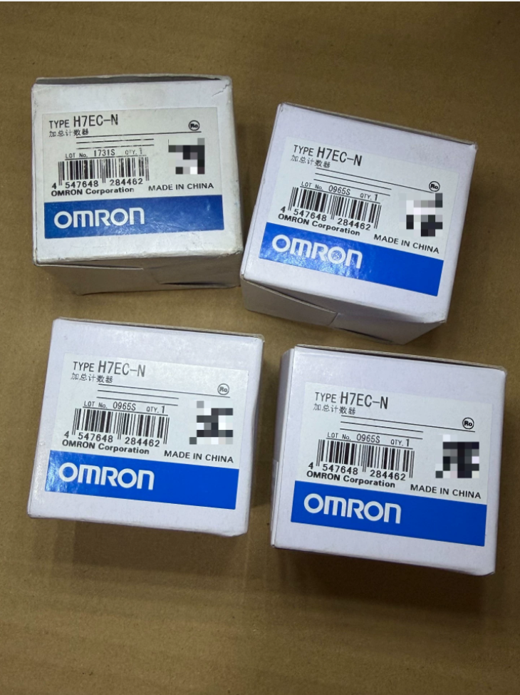

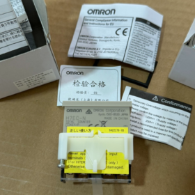
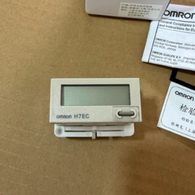
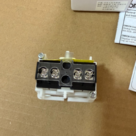
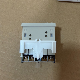
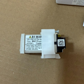
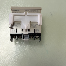
Autoalimentat (built-in lithium battery), 8-digit total counting, No-voltage(dry-contact) intrare, panel flush-mount, counting data retained upon power loss
- Codul modelului Explicația
H7EC: 8-cifră totalizing counter serie
N: 1/32 DIN panel mounting, self-powered by internal battery, No-voltage (dry-contact) intrare
B suffix: Black housing; no -B = light-gray housing
Distinguish similar models:
H7EC-NV: DC4.5-30V voltage input (NPN/PNP)
H7EC-NFV: AC/DC wide-range voltage input
H: With backlight (backlight requires external DC24V power; counting still powered by internal battery)
- Specificatii tehnice principale
| Articol | H7EC‑N |
| Afişa | 8‑digit LCD, character height:8.6 mm, zero‑suppression display, no backlight |
| Counting Range | 0‑99999999, Up‑count only |
| Tip de intrare | No‑voltage dry‑contact input (întrerupătoare, contacte releu) |
| Max. Counting Speed | 30 Hz / 1 kHz, selectable via side DIP switch |
| Minimum Signal Width | 30Hz:16.7 Domnișoară; 1kHz:0.5 Domnișoară |
| Resetați | Front‑panel manual reset + external terminal reset; key‑lock switch to disable front‑panel reset key |
| Minimum Reset Pulse Width | ≥20 ms |
| Alimentare electrică | Built‑in 3V lithium battery Y92S‑36; nu este necesară alimentarea externă; data backup; replaceable battery |
| Battery Service Life | Approx.10 years standby; approx.5 years continuous counting @30Hz; approx.4 years continuous counting @1kHz |
| Instalare | Flush panel mount, 1/32 DIN; Cut‑out:45×22.2 mm; Dimensiunea de ansamblu:48×24×48.5 mm |
| Panel Protection Rating | IP66 (with waterproof gasket fitted) |
| Temperatura de operare | -10~+55℃ |
| Terminale | Screw‑type terminals |
- Wiring Instructions for H7EC-N (No-voltage Input)
This unit requires NO external operating power. Only counting-signal and reset-signal wiring needed.
- Count Input Terminals: Connect to switch or relay dry-contacts. One complete count is triggered by contact closure followed by opening.
- Reset Terminals: Short-circuit external dry-contact to perform reset. Manual reset key is also available on front panel.
- Side-mount DIP switches:
SPEED: Select counting speed:30Hz /1kHz
KEY-LOCK: Key protection. ON=Front-panel reset locked, only external reset available; OFF=Front-panel reset enabled.
⚠️Important: H7EC-N cannot directly connect NPN/PNP proximity sensors! Use H7EC-NV (voltage-input model) for proximity sensors.
- Precauții de aplicare
- New unit: Remove battery insulating sheet, otherwise no display and no counting.
- Battery specification: Use dedicated Y92S-36 (3V Li-Mn battery). Do not substitute other battery types. Flashing display indicates low battery. Count data will be lost during battery replacement.
- This is dry-contact input. Avoid induced-voltage interference. Keep signal cables separated from high-power cables.
- Reset condition: KEY-LOCK must be OFF for front-panel reset to work. External reset is independent of key-lock setting.
- No built-in backlight. For backlight version select H7EC-NV-H series; backlight needs external DC24V supply.
- Depanare comună
- No counting: Check speed-setting DIP switch; verify pulse width meets minimum requirement; confirm battery insulating sheet removed.
- Front-panel reset ineffective: Check KEY-LOCK DIP switch, set to OFF.
- Flashing display: Low internal battery, replace Y92S-36.
- Spurious / random counting: Signal cable runs in parallel with high-voltage power wiring causing induced interference; use shielded cable or shorten wiring length.
- Domestic Replacement Reference
8-digit totalizing counter 48×24 mm with built-in battery, dry-contact input. Key selection criteria:
Intrare: No-voltage dry-contact input
Counting speed switchable between 30Hz /1kHz
Manual + external reset, key-lock function, field-replaceable internal lithium battery
Panel cut-out dimension:45×22.2 mm
Counting Accuracy of Omron H7EC-N
H7EC-N is a pulse-driven totalizing counter, NOT an hour meter. Official datasheet provides NO percentage or ppm counting-error specifications. (±100ppm is the time-accuracy specification for H7ET series hour meters and does NOT apply to H7EC counters.)
- Counting Principle
Counting logic: +1 count for every valid input pulse. Valid pulse → increment count; invalid pulse → no increment. This is event-based pulse counting with no inherent analog-measurement error.
Under valid input-pulse conditions, zero theoretical counting error. All practical errors originate from external signals, wiring interference or insufficient pulse width.
✅Mandatory Pulse Conditions for Reliable Counting
| Setare | Max. Counting Rate | Minimum Pulse Width (ON/OFF ratio 1:1) |
| 30Hz setting | 30 pulses/second | ≥16.7 ms |
| 1kHz setting | 1000 pulses/second | ≥0.5 ms |
If input pulse width < minimum specification → pulse not detected → count loss.
Contact bounce or electrical interference → extra false pulses → over-counting.
No-voltage input threshold criteria:
PE (count trigger): Contact closed impedance ≤10 kΩ
OFF: Contact open impedance ≥750 kΩ, residual voltage ≤0.5 V
- Frequently-Confused Specifications
- H7ET-N (Hour Meter): Time accuracy ±100ppm @25℃, used for elapsed-time measurement, not pulse counting.
- H7EC-N (Contra): Only accumulates input pulses. No “±XX% accuracy” parameter. Count reliability depends entirely upon quality of incoming pulses.
- Practical On-site Error Sources
- Mechanical-contact bounce: Releu / limit-switch bounce generates multiple spurious pulses → over-counting.
- Insufficient pulse width: Input pulse narrower than minimum specification → count loss.
- Wiring interference: Signal cable routed alongside power cables, induced voltage causes false triggering.
- Wrong speed DIP-switch setting: High-speed pulses applied under 30Hz setting → massive count loss.
- Practical Recommendations to Ensure Counting Accuracy
- Input pulse frequency shall not exceed the selected speed setting. Pulse width must exceed the minimum specification.
- Add RC bounce-suppression circuit for mechanical contacts to avoid over-counting caused by bounce.
- Separate counting signal wiring from power cables; shielded cable is recommended for long runs.
- Observe LCD decimal-point indicator: Decimal-point flickers upon receiving valid pulse; no flicker = counter detects no incoming pulse.
H7EC-N On-site Quick Commissioning & Troubleshooting Procedure
H7EC-N: Dry-contact input, alimentat cu baterie, no external supply required. Flickering LCD decimal-point = valid counting-pulse received; key diagnostic indicator for field work.
Troubleshooting sequence: Baterie & visual inspection → DIP-switch configuration → Reset-function test → Bench signal simulation test → Actual field-signal test → Interference mitigation.
Step 1: Troubleshooting no-display / new-unit issues
- Confirm battery insulating sheet is removed. Unit will show blank screen if sheet remains fitted.
- Flashing digits: Y92S-36 battery low. Înlocuiți bateria; all stored count data is lost during replacement.
- Completely blank screen: Failed battery; replace Y92S-36.
⚠️Disconnect all wiring before battery replacement. Only use specified battery model.
Step 2: Verify side-mount DIP-switch settings (critic)
Two DIP switches located on side casing:
- SPEED (Counting Speed)
30Hz: For mechanical switches / limit switches, min. pulse width ≥16.7 ms
1kHz: For high-speed dry-contact signals, min. pulse width ≥0.5 ms
If actual signal frequency exceeds selected setting, pulses will be missed! Do NOT select 1kHz for mechanical switches; high risk of bounce-caused over-counts.
- KEY-LOCK (Key-lock function)
OFF: Front-panel RST reset key enabled
PE: Front-panel RST key locked, only external-terminal reset works. Many misdiagnose locked state as counter failure.
Step 3: Reset-function Test
- Set KEY-LOCK to OFF. Press front-panel RST key; reading shall reset to zero → Manual reset functional.
- Set KEY-LOCK to ON. Front-panel key has no effect. Short-circuit external reset terminals for ≥20 ms; reading shall reset → External reset functional.
External reset needs ≥20 ms continuous short-circuit. Momentary touch will NOT trigger reset.
Step 4: Bench-top functional test of counter (without field wiring)
Simulate counting pulses by manually short-circuiting count-input terminals
- Repeatedly short-circuit and open count-input terminals by hand.
- LCD decimal-point flickers once for each valid pulse and count increments by 1.
✅Decimal-point flickers and count increases: Counter hardware OK. Fault lies in external wiring / întrerupătoare / senzori.
❌No decimal-point flicker: Cabluri slăbite, incorrect DIP-switch setting or hardware damage.
Important reminder: H7EC-N is No-voltage dry-contact input. Do NOT directly connect NPN/PNP proximity sensors! Use H7EC-NV for proximity-switch inputs. Improper connection results in erratic counting or no counting.
Step 5: Diagnosis of Four Typical Fault Conditions
Defecțiune1: No counting, no increment despite external-switch actuation
- Observe decimal-point: No flicker → Counter receives no valid signal.
- Check terminal screw tightness and wire continuity.
- SPEED setting: Mechanical-switch applications set to 30Hz, not 1kHz.
- Verify switch performance with multimeter continuity test.
- Confirm signal source provides dry-contact closure, not voltage-output signal.
Defecțiunea 2: Count loss; actual events exceed counter increment
- Input-signal frequency exceeds SPEED-setting maximum (e.g.80Hz signal with 30Hz selected → heavy pulse loss).
- Input-pulse width below minimum specification.
- Poor-contact switching, incomplete valid pulses.
Remediu: Reduce operating speed; adjust cam / switch timing to satisfy minimum pulse-width requirement.
Defecțiunea 3: Spontaneous count increment without physical actuation (most-common field fault)
- Mechanical-contact bounce: Releu / limit-switch bounce creates multiple false pulses.
✅Solution: Fit RC bounce-suppression network across contact terminals (R≈1k-10k, C≈0.1μF).
- Wiring interference: Count-signal cable routed alongside 220V power wiring; induced voltage triggers false counts.
✅Solution: Separate signal and power cables; use shielded cable with shield grounded at cabinet-side only; shorten cable runs.
- Leakage current from peripheral equipment produces residual current in open-state condition, causing false triggering.
Defecțiune4: Front-panel reset key does not zero reading
- Check KEY-LOCK DIP-switch. If set ON, toggle to OFF.
- If front-panel key aging suspected: Test via external-terminal reset. Successful external reset confirms counter hardware integrity.
Step 6: On-site EMC & anti-interference guidelines specific to H7EC-N
- Count-signal cables must NOT share cable trunking with motor, contactor or VFD power cables; maintain ≥10 mm physical separation.
- Use shielded cable for long-distance runs; connect shield to cabinet ground only at cabinet end (counter end ungrounded).
- Always fit RC bounce-suppression for mechanical-contact inputs, especially under 1kHz setting.
- Terminal screw tightening torque 0.98 N·m. Avoid over-torque to prevent terminal damage.
Quick-reference Troubleshooting Mnemonic
Watch decimal-point flicker: flicker = valid pulse received; no flicker = no incoming signal; random increments = interference / contact bounce; reset failure = key-lock engaged; flashing digits = replace battery.
Omron H7EC-N Dimensions (Unitate:mm)
- Overall Physical Dimensions (W × H × Depth)
Front-panel frame: 48(lăţime) × 24(înălţime) mm (1/32 DIN standard)
Overall depth (front-panel surface to rear of terminals): 48.5 mm
Complete unit dimension: 48 × 24 × 48.5 mm, weight approx.60 g
- Cabinet Panel Cut-out Dimension (Sheet-metal opening)
45.0(lăţime) × 22.2(înălţime) mm
Toleranţă: width +0.5 mm, height +0.5 mm
Suitable sheet-metal thickness: 1~6 mm
✅Sheet-metal cut-out = 45×22.2 mm. Do NOT cut to 48×24 mm (48×24 is outer frame dimension, not cut-out).
- Note de instalare
- IP66 front-panel protection rating is lost when multiple units are densely mounted side-by-side. Maintain ≥2.5 mm gap for IP66 performance.
- Terminal screw size M3.5, cuplul de strângere:0.98 N·m.
- H7EC-NV / H7EC-NFV share identical physical dimension and cut-out size; direct panel-to-panel replacement is possible.
Quick Memorization
Outer frame size:48×24 mm
Sheet-metal cut-out: 45 × 22.2 mm
Minimum internal cabinet depth clearance ≥ 50 mm





NH42-63-318x560.png "Comutatoare de transfer automat de tip PC CHINT (ATS)NH42-63/4SZ")



