 Contactor,întrerupător de circuit,senzor,Codificator,PLC,Convertor

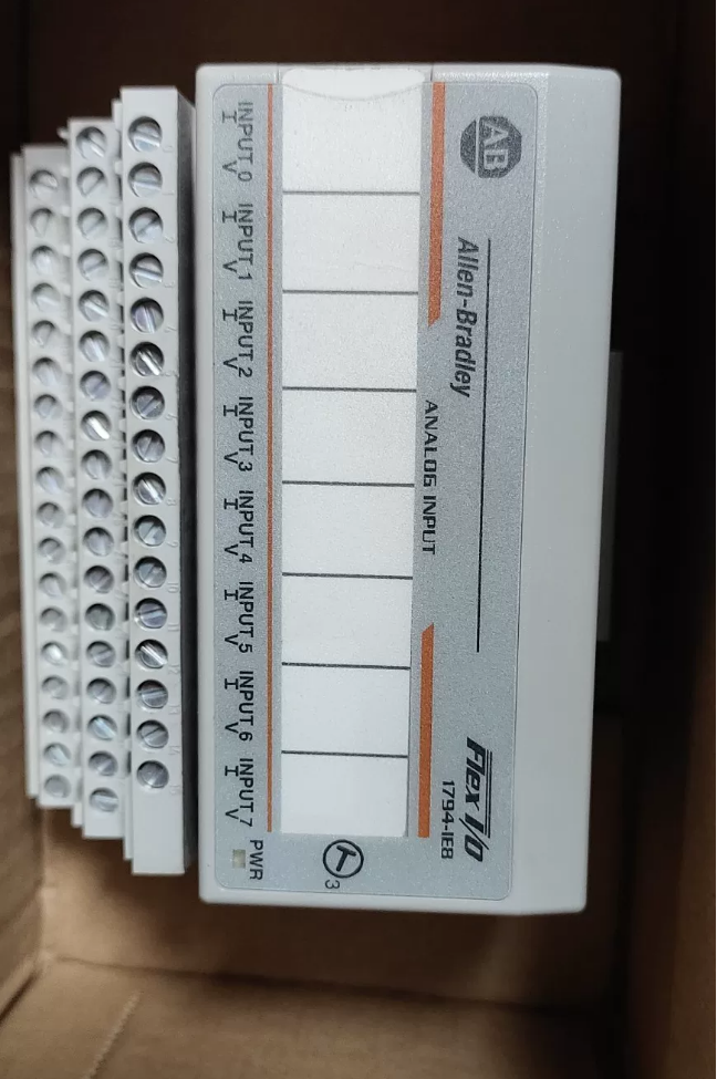

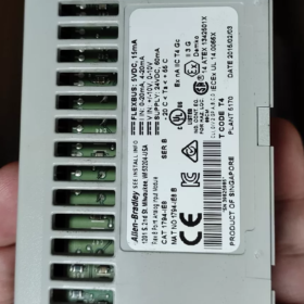
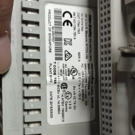
This is a FLEX I/O distributed analog input module. 1794-IE8B = 1794-IE8 Series B. “B” denotes hardware series revision instead of part number suffix; it is commonly referred to as 1794-IE8B in the industry.
✅ Basic Information
Model: 1794-IE8 (Seria B, commonly called 1794-IE8B)
Marca: Rockwell Allen-Bradley
Tip: 8-channel single-ended non-isolated analog input module
Sistem: FLEX I/O distributed I/O, used with 1794 adapters (1794-AENT, 1794-ASB, etc.)
Matching Terminal Base: 1794-TB3 / TB3G terminal base (trebuie comandat separat)
Ciclu de viață: Produs activ, available for new purchase and repair, not discontinued
📋 Core Technical Specifications
| Articol | Parametru |
| Canale | 8 single-ended analog inputs, non-isolated between channels |
| Signal Ranges (software configurable per channel) | 4~20mA, 0~20mA, 0~10V, ±10V |
| Rezoluţie | Unipolar: 12pic; Bipolar: 11pic + semn bit; Data format: 16-bit left-justified two’s complement |
| Timp de conversie | Total conversion time for all channels: 256μs |
| Precizie | 0.29% FS absolute full-scale accuracy at 25°C |
| Alimentare electrică | 24VDC (19.2~31.2VDC), module current draw approx. 60mA @24VDC |
| Temperatura de operare | 0°C ~ +55°C |
| Montare | DIN rail, FLEX I/O local bus (Flexbus) |
| Software | Studio5000 / RSLogix5000 configuration |
🧩 Application Scenarios
FLEX I/O remote distributed analog acquisition: transmitters for pressure, temperatură, nivel, flow with 4-20mA signal, 0-10V valve feedback. Widely used as remote I/O station for ControlLogix systems.
Nota: No galvanic isolation between channels. Large ground potential difference among multiple sensors will cause common-mode interference. External signal isolator is required.
🔌 LED Indicator Definition
Verde solid: Module healthy, communication OK
Roșu continuu: Module fault / configuration mismatch (electronic key error)
Flashing red: Communication loss with FLEX adapter
Oprit: No 24VDC power supply or hardware damage
⚠️ Common Troubleshooting Points
- Verify correct base model, no bent bus pins; module must fully engage and lock into base latches
- Confirm 24VDC supply voltage within 19.2~31.2V range
- Studio5000 configuration: Exact Match electronic key recommended; each channel range must match field sensor
- Fluctuația semnalului: Check grounding. For single-ended input, add isolator if ground offset exists
- No reading: Inspect terminal wiring, distinguish current/voltage terminals; current loop must form closed circuit
📌 Alternative / Related Series Reference
Same family: 1794-IE8K (conformal coated version), 1794-IE8XT (wide-temperature XT version)
Alternativă internă: Distributed analog input module (must match remote bus protocol)
📦 HS Code Reference (Comerțul Internațional)
85371011 (Programmable controller I/O module, subject to customs broker final confirmation)
1794-IE8A (Series A) vs 1794-IE8B (Seria B)
Base part number remains 1794-IE8. A/B stand for hardware series revision, not separate part numbers. Aspect, baza, cablare, gamă, resolution and accuracy are fully interchangeable for physical installation. Differences lie in power-up behavior before configuration, data word structure and explosion-proof certification.
- Diferențele cheie (Official Manual Highlights)
| Element de comparație | 1794‑IE8 Series A (Commonly called 1794‑IE8A) | 1794‑IE8 Series B (Commonly called 1794‑IE8B) |
| Unconfigured Power-up Behavior (Cel mai critic) | When module powers up before configuration download, channels return fixed false readings of approx. 2V or 4mA. PLC receives non-zero value which may trigger false interlock or alarm. | Nou “OFF” range added. Channels return 0V / 0mA before configuration, eliminating false analog readings for safer commissioning. |
| Data Word: Power-Up Status Bit | No such status bit | Input data word includes Power-Up bit. The bit is set once module power-up completes. Program can detect module startup to implement power-up masking logic. |
| Explosion-proof Certification | No Zone2 certification | New IECEx / ATEX Zone2 certification: Ex ec IIC T4 Gc, suitable for Division 2 zone periculoase |
| Hardware / Circuit | Legacy PCB with older components | PCB redesign, updated component bill of materials, fixes power-up reading drift issue of A-series |
| Software Configuration Compatibility | RSLogix5000 configured as Series A | Studio5000 / RSLogix5000 configured as Series B; backward compatible with A mode. B module can use A configuration directly to replace legacy A module. |
| Ciclu de viață | Învechit, only second-hand/spare parts available | Activ, new units available for purchase |
- Caracteristici comune (Field Replacement Highlights)
- Canale: 8-channel single-ended non-isolated analog input, ranges 4~20mA, 0~20mA, 0~10V, ±10V
- Rezoluţie, conversion speed, precizie, 24VDC supply and operating temperature range are identical
- Compatible terminal bases: 1794-TB3 / TB3G, identical wiring diagram
- Bus: FLEX I/O Flexbus, compatible with all FLEX adapters such as 1794-AENT, ASB
III. Engineering Replacement Considerations
- A → B Replacement
Physical plug-and-play installation. Existing A-series configuration can be retained (B module supports A compatibility mode), or switch to B configuration to enable power-up status bit.
✅ Recommendation: Keep original configuration, no program modification required for direct replacement.
- B → A Replacement
Physically installable. Cu toate acestea, A module returns false 4mA/2V readings when powered up without configuration. Take precautions for interlock to prevent equipment false action during commissioning or restart.
- Cheie electronică: If `Exact Match` strict matching is set in Studio5000, A and B revision mismatch triggers configuration fault. Switch to `Compatible Module` compatibility mode.
- Recomandare de selecție
New projects and hazardous areas: Prefer 1794-IE8B for safe zero signal on power-up
Spare parts for legacy system: B can replace failed A module. If system is sensitive to analog signal transient at startup, implement power-up delay masking logic in PLC program.
Rockwell Allen-Bradley 1794-IE8B (1794-IE8 Series B) Specificații tehnice detaliate
FLEX I/O 8-channel single-ended non-isolated analog input module
- Informații de bază
Model: 1794-IE8 Series B (Commonly called 1794-IE8B)
Marca: Rockwell Automation Allen-Bradley
Tip: Analog Input AI, 8 single-ended inputs
Bus: FLEXBUS (FLEX I/O backplane local bus)
Matching Terminal Base: 1794-TB3 / 1794-TB3G (must be purchased separately)
Supported Adapters: 1794-AENT, 1794-ASB, 1794-ADN and other FLEX I/O adapters
Supported Software: RSLogix5000 / Studio5000
Origine: Singapore; Standard Warranty: 1 an
Explosion-proof Certification: IECEx / ATEX Ex ec IIC T4 Gc (Zone2) (Exclusive for B series, not available for A series)
- Channel Electrical Specifications
| Articol | Parametru |
| Numărul de canale | 8 canale, single-ended, no galvanic isolation between channels |
| Configurable Ranges (per-channel independent configuration) | 4~20mA, 0~20mA, 0~10V, ±10V, OFF range (new for B series) |
| Rezoluţie | Unipolar: 12 pic; Bipolar: 11 pic + semn bit |
| Format de date | 16-bit left-justified two’s complement |
| Quantization LSB | Voltaj: 2.56 mV/count; Actual: 5.13 μA/count |
| Total Conversion Time | Toate 8 channels total conversion: 256 μs |
| 25°C Full Scale Absolute Accuracy | 0.29% FS (voltage and current) |
| Full Temperature Range Accuracy (0~55°C) | 0.5% FS |
| Common Mode Voltage | ±50V (common-mode rejection only, not galvanic isolation) |
| CMRR (Common Mode Rejection Ratio) | ≥60dB @50/60Hz, source impedance 249Ω |
| NMRR (Normal Mode Rejection Ratio) | ≥40dB @50/60Hz |
| Impedanta de intrare | Modul de tensiune: >1MΩ; Modul curent: 250Oh |
| Unconfigured Power-up State | B-series: channels return 0mA/0V; built-in Power-Up status bit |
III. Power Supply Specifications
| Articol | Parametru |
| External Module 24V DC Supply | 19.2 ~ 31.2 VDC, nominal 24VDC |
| Module Power Consumption Current | 60mA @24VDC |
| Backplane 5V FLEXBUS Current | Typical 30mA (supplied by FLEX adapter) |
| Field Loop Current | Current transmitter loop powered by external 24V supply, module only samples signal |
- de mediu & Specificatii mecanice
| Articol | Parametru |
| Temperatura de operare | 0°C ~ +55°C (32℉ ~ 131℉) |
| Temperatura de depozitare | -40°C ~ +85°C |
| Umiditatea relativă | 5%~95%, necondens |
| Vibrație | IEC60068‑2‑6, 10~150 Hz, 1g |
| Şoc | IEC60068‑2‑27, 30g peak |
| Metoda de montare | Montare pe șină DIN, stacked on FLEX I/O base |
| Protecție la intrare | IP20 (module body, installed inside control cabinet) |
| EMC | Conform EN 61006 industrial immunity standard |
- LED Status Indicators
Verde solid: Module healthy, comunicare / configuration OK
Roșu continuu: Defecțiune hardware / electronic key mismatch, eroare de configurare
Flashing red: FLEXBUS communication interrupted, lost connection with adapter
Oprit: Loss of 24V supply or backplane power
- Structura datelor (B-Series Exclusive)
- Input data area: 16-bit raw analog count values for 8 canale
- Power-Up status bit (new for B series): Bit is set once module power-up completes. PLC program can read it to mask signals during startup and prevent interlock false action
- Configuration word: Individual channel range selection, supports OFF range to force zero signal when unconfigured
VII. Limitări critice (Engineering Focus)
- No channel isolation: Single-ended input. External signal isolator is mandatory when large ground potential difference exists among field sensors, otherwise drift and signal jitter will occur
- Intrare curent: Internal 250Ω sampling resistor inside module; transmitter loop must form closed circuit
- Cheie electronică: Studio5000 configuration, Exact Match for strict revision check. A/B revision mismatch triggers fault under strict mode; switch to Compatible Module for replacement
VIII. Related Derivative Models
1794-IE8K: Conformal coated version
1794-IE8XT: Wide temperature XT version, operating temperature -40~70℃
1794-IE8A: Legacy A version, no Zone2 explosion-proof rating, no zero signal on power-up, no Power-Up bit
- HS Code Reference (Customs Declaration)
85371011, Programmable Controller I/O Module (final confirmation required from customs broker)
Rockwell 1794-IE8B Installation Method (FLEX I/O)
Separated structure: Terminal base (1794-TB3 / TB3G) mounts on DIN rail first, then plug 1794-IE8B module onto base. Module body cannot be fastened directly onto rail.
- Mounting Carrier
- Rail Specification: Standard 35×7.5mm EN50022 DIN rail (AB part 199-DR1). Horizontal mounting inside cabinet preferred. Add rail stop 1492-EA35 for anti-vibration if vertically mounted
- Alternativă: Panel Screw Mount: Base has mounting holes for direct screw fastening on cabinet backplate (not recommended for high vibration applications)
- Matching Base: Must use 1794-TB3 / 1794-TB3G. TB3G is spring-cage tool-free terminal. Base integrates Flexbus internal bus connector for daisy-chaining adjacent adapters/bases
- Complete Installation Procedure (Official Standard Process)
⚠️ Critical Safety Rule: Base removal is prohibited under power; module hot-swap is electrically allowed but not recommended for frequent field operation
Pasul 1: Mount Terminal Base onto DIN Rail
- Hook upper latch of base onto DIN rail, press down base until latch clicks and locks
- Daisy-chain multiple bases/adapters: Fully retract Flexbus connector inside base first, push base tightly against left adapter/base, then push Flexbus connector leftward and insert into adjacent unit to complete FLEXBUS backplane connection
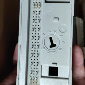
- Set base model key switch: Poziţie 3 for 1794-IE8 (small rotary switch on base side; wrong setting leads to module identification failure)
- Install end stops on both rail ends to prevent base sliding
Step2: Install 1794-IE8B Electronic Module
- Inspect bottom gold fingers of module for bending or damage
- Align upper module guide rib with base guide slot, align vertically to base
- Press module down evenly until both side latches of base automatically lock (audible click), module fits flush against base
Do not apply excessive force, risk bending 16-pin bottom bus pins
Step3: Terminal Wiring
- Row C terminals of base: 24VDC power; Row B: 24V common and channel ground; Row A: 8-channel analog signal inputs
- Shielded twisted pair recommended for analog signal cable, shield single-point grounded; current signal loop must be closed
- Close terminal protective cover after wiring completion
Step4: Pre-Power-up Inspection
- Base key switch set to 3
- All Flexbus connectors fully engaged, no gaps between bases
- Module latches fully locked
- 24V supply voltage: 19.2~31.2VDC
- Verify signal cable free of short circuit and misconnection
III. Mediul de instalare & Layout Requirements
- Mounting location: IP20 inside control cabinet, keep away from strong interference and heat sources such as VFDs, contactors and transformers
- Disiparea căldurii: Reserve ventilation gap above and below module; operating temperature range 0~55℃
- Împământare: Use galvanized steel DIN rail with reliable protective earth connection; aluminum rail not recommended for poor grounding performance
- Vibration application: Horizontal mounting optimal; rail locking components required for vertical installation
- Removal Procedure
- Disconnect field 24V signal circuit (recomandat)
- Press both side release latches of base, lift 1794-IE8B module upward for removal (base remains on DIN rail)
- To remove base: Retract Flexbus connector first, pry bottom DIN latch with flat screwdriver then lift base upward
- Common Installation Errors
- Base key switch not set to 3 → Module faults on power-up, cannot be recognized by configuration
- Flexbus connector not pushed out or incomplete engagement → FLEXBUS communication loss, module red flashing
- Module not fully seated, latches unlocked → Intermittent communication under vibration
- Gaps between bases, floating bus connector → Unstable communication
- High power cables and signal cables routed in same trunk → Analog signal drift and fluctuation
- Installation Quick Notes
Base fixed on DIN rail + module plugged onto base (split structure)
Key switch setting: 3
Flexbus daisy chain: Retract connector first, butt units tightly then extend connector
Modul: Align guide slot, press evenly until side latches lock
Never remove base while powered (interrupts FLEXBUS backplane bus)



NH42-63-318x560.png "Comutatoare de transfer automat de tip PC CHINT (ATS)NH42-63/4SZ")



