 Contactor,întrerupător de circuit,senzor,Codificator,PLC,Convertor

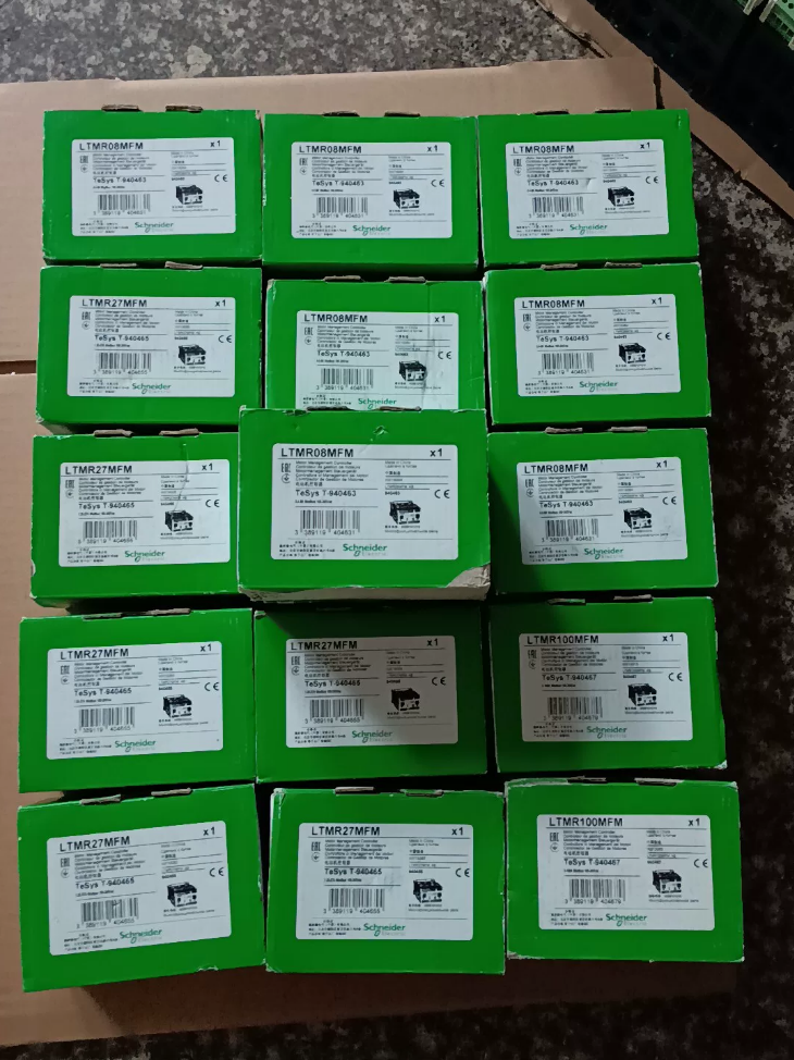

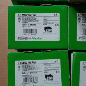
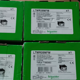
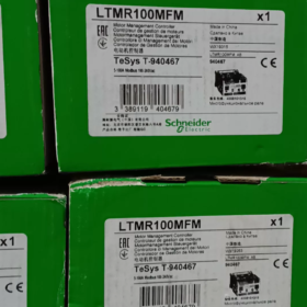
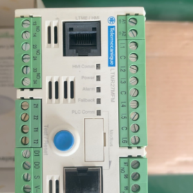
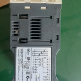
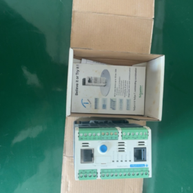
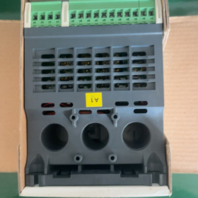
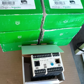
Application Fields of Schneider LTMR27MFM (TeSys T)
Current rating: 1.35~27A intelligent management controller for 3-phase asynchronous motors, equipped with Modbus-RTU communication. Widely deployed inside MCC cabinets for integrated motor protection, current monitoring and remote data transmission.
Defalcarea codului de model
LTMR27MFM
LTMR: TeSys T motor management controller base unit
27: Current measuring range 1.35~27 A (integrated current transformers)
M: Communication interface → Modbus RS485
FM: Control supply 100~240 VAC (AC)
Cross reference within series: LTMR27EFM = Ethernet; LTMR27CFM = CANopen
- Specificații electrice principale
| Articol | Parametru |
| Motor current range | 1.35 … 27 O (built-in CT, no external current transformer required) |
| Alimentarea controlerului | 100~240 V AC 50/60 Hz (wide tolerance: 93.5~264 V) |
| Comunicare | Modbus RTU RS485, bloc terminal + RJ45 dual port; address 1~247; baud rate 1.2k~19.2k |
| I/O digitală | 6 intrări digitale; 3 FĂRĂ ieșiri cu releu + 1 fault relay (1NU+1NC) |
| Relay contact rating | 5A /250VAC; 5A /30VDC |
| Montare | Montare pe șină DIN |
| Dimensiuni de gabarit | W91 mm × H61 mm × D122.5 mm; Greutate netă 0.53 kg |
| Temperatura de functionare | -20 ℃ ~ +60 ℃; Storage temperature -40~80 ℃ |
| Clasa de protectie | IP20 (for cabinet internal installation) |
- Built-in Protection Functions
✅ Thermal overload protection (thermal model)
✅ Phase loss & 3-phase current unbalance protection
✅ Locked rotor protection, long start protection
✅ Underload protection (dry-running/belt breakage monitoring)
✅ Earth fault protection (internal or external zero-sequence CT)
✅ Support for PTC motor thermistor input
✅ Fault logging, trip history, contor de ore de functionare
- Measurement Capability (Voltaj & power measurement with LTME extension module)
Base unit measurement: 3-phase current, average current, unbalance current, earth fault current;
When fitted with LTME extension module: additional 3-phase voltage, putere activă/reactivă, factor de putere, contorizarea energiei.
- Software de punere în funcțiune
Configuration via SoMove software (TeSys T DTM). Connect PC directly via front RJ45 HMI port for parameter setting, fault reading and real-time monitoring.
Optional local display panel: LTMCU / LTMCUF.
- Lifecycle Notice
The full LTMR TeSys T series is undergoing phase-out (EOL).
Official order cutoff date: 30 sept 2026; Technical support ends: 31 Jan 2027
Înlocuire de nouă generație: TeSys Tera
Unitatea principală: LTMTMFM (Modbus, 100~240VAC/DC)
Match current sensor:
2.5~25A → LTMTCTV25UT (closest match for original 1.35~27A application)
⚠️ Wiring layout and Modbus register mapping are not fully compatible between old and new series. On-site retrofit requires program re-commissioning.
- Aplicație tipică
MCC Motor Control Centers, pompe de apa, fani, compresoare, transportoare; projects in water treatment, HVAC, metallurgy and cement industries.
- Quick Distinction of Similar Models
LTMR27MFM:1.35~27A, Modbus, 100~240VAC
LTMR100MFM:5~100A, Modbus, 100~240VAC
LTMR27EFM:1.35~27A, Ethernet/IP
Main Industry Segments
- Alimentare cu apă municipală & Wastewater Treatment (Aplicația cea mai comună)
✅ Municipal wastewater plants, waterworks, pumping stations
✅ Typical loads: pompe submersibile, centrifugal pumps, pompe de retur nămol, suflante de aerare, răzuitoare
Key requirements satisfied: protectie la subsarcina (dry-run prevention), protectie la pamant, remote fault alarming, energy monitoring.
- HVAC, Clădiri Comerciale & Constructii Sisteme Electromecanice
✅ Shopping malls, spitale, centre de date, industrial park chiller plants
✅ Typical loads: pompe de apă răcită, pompe de apa de racire, ventilatoare turn de răcire, ventilatoare de evacuare, AHU fans
Avantaj: suprasarcină termică & locked rotor protection; Modbus connection to building BA system for current data and fault signals.
- Ciment, Materiale de constructii & Aggregate Mining Production Lines
✅ Belt conveyors, ascensoare cu cupe, auxiliary drives for roller presses, dust extraction fans, silo discharge equipment
✅ Targeted protection: locked rotor protection, long start protection, phase unbalance protection to avoid motor burnout caused by mechanical jamming.
- Chimic & Industria farmaceutică
✅ Circulation pumps, agitator motors, auxiliary air compressor motors, dust fans
✅ Supports PTC thermistor connection for motor winding temperature monitoring; fast tripping upon phase loss and earth faults to meet industrial safety standards.
- Mâncare & Băutură, Packaging Production Lines
✅ Conveyor motors, blowers, wash pumps, packaging machine drives
Accurate underload monitoring to detect material shortage or belt detachment; fault history facilitates production maintenance.
- Tranzit Feroviar & Tunnel Electromechanical Systems
✅ Tunnel jet fans, drainage pumps, ventilatoare de evacuare a fumului
Reliable protection for fire service motors; data upload to tunnel PLC control system.
- Power Plant Auxiliary Equipment
✅ Circulating water pumps, ventilation fans, ash handling conveyors; standard component inside power station MCC rooms.
- Port & Depozitare logistică
✅ Conveyors, stacker auxiliary drives, dust extraction fans, hydraulic station oil pumps
Matching Motor Power Reference (380V 3-phase motors)
LTMR27MFM measuring range 1.35~27A
Suitable motor power range: 0.75kW~13kW three-phase asynchronous motor.
Scenarii de aplicații nerecomandate
- Motors above 13kW (select LTMR100 series instead)
- Equipment with frequent forward/reverse rotation and heavy impulse jogging operation (thermal model parameters require special evaluation)
- Explosion-proof enclosures without sufficient heat dissipation (ambient temperature must remain ≤60℃)
Selection Advantages Matched to Operating Conditions
Integrated current transformers, no external CT required, simplifies cabinet wiring;
Modbus RS485 interface, seamless connection with Schneider PLC (Modicon M241/M251/M340 etc.);
Comprehensive protection suite: suprasarcina, rotor blocat, pierdere de fază, current unbalance, subîncărcare, defect la pământ, PTC temperature monitoring;
Fault history recording & running hour statistics, compliant with smart factory and energy management projects.
Operating Principle of Locked Rotor Protection on Schneider TeSys T LTMR27MFM
The LTMR27MFM implements locked rotor protection via real-time 3-phase current sampling + time threshold judgment, split into two independent configurable modes: Locked Rotor Protection during Start-up and Locked Rotor Protection in Running State.
- Hardware Foundation
The LTMR27MFM integrates built-in 3-phase current transformers to continuously sample stator current at high speed. The internal MCU calculates in real time:
- RMS value of three-phase currents
- Ratio between instantaneous current and rated operating current
- Duration of over-limit condition
No additional external sensors required; diagnosis relies purely on current signature analysis.
- Two Locked Rotor Protection Modes (Independently configured in SoMove)
Mode 1: Locked Rotor Protection during Motor Start-up
Application scenario: Motor cannot accelerate due to mechanical jamming at startup
- Judgment window: Controller identifies startup sequence (current surge, motor at standstill before acceleration)
- Logică:
If start-up current > Locked Rotor Start Threshold, and duration ≥ Locked Rotor Start Delay → Trip command triggered
- Adjustable parameters (SoMove):
Locked rotor start current: typical range 1.5~8× motor rated current Ie (default 5Ie)
Locked rotor start delay: typical range 0.5~10 s
Scop: Prevent winding burnout caused by prolonged high current when motor is blocked on startup; distinguish permanent stall from normal short-duration starting inrush current.
Mode 2: Locked Rotor Protection during Steady-State Operation
Application scenario: Mechanical blockage occurs after motor reaches rated speed (belt jamming, pump impeller stuck, foreign object entrapment)
- Judgment window: Controller confirms motor completes acceleration and enters stable operation
- Logică:
If operating current > Running Locked Rotor Threshold, and duration ≥ Running Locked Rotor Delay → Trip command triggered
- Parameter characteristics:
Running locked rotor threshold is generally set lower than start-up threshold (typically 1.8~4 Ie), with shorter delay for rapid fault isolation.
- Full Internal Decision Workflow
- LTMR continuously samples three-phase currents and monitors current variation trends;
- Automatically distinguishes three operating states: Standstill → Start-up → Steady Run;
- Activates corresponding locked rotor threshold rules according to operating state;
- Starts timing once current exceeds set threshold continuously;
- When timing reaches configured delay:
✅ Internal protection sequence activated;
✅ Fault relay contact changes state;
✅ Disconnects contactor control circuit;
✅ Stores fault code BLR (Blocked Rotor) locally;
✅ Uploads locked rotor fault information to upper-level PLC via Modbus.
⚠️ Critical Distinction: Locked Rotor Protection ≠ Thermal Overload Protection
Protecție la suprasarcină termică: Based on motor thermal accumulation model, trips for sustained mild overload; slow response characteristic.
Locked Rotor Protection: Fast acting definite-time protection against severe instantaneous overcurrent caused by mechanical stall, compensating the slow response of thermal protection.
- Key Commissioning Guidelines
- Motor rated current Ie must be entered accurately
All locked rotor thresholds are calculated as multiples of Ie. Incorrect setting leads to protection failure.
- Tuning principles for delay
Fani & centrifugal pumps: Longer natural startup time → extend start-up locked rotor delay to avoid nuisance tripping.
Transportoare & concasoare: High risk of mechanical jamming → minimize running locked rotor delay for fast protection.
- Coordonarea protecției
Locked rotor protection can be enabled together with phase loss, dezechilibra, underload and PTC temperature protection for multi-layer safety.
- Common setting pitfall
Do not set locked rotor threshold higher than the actual motor starting inrush current; otherwise protection will fail to respond during blocked startup.
- Fault Identification After Trip
With local display panel LTMCU: Fault code BLR shown on screen
SoMove fault log: Recorded as Blocked rotor
Corresponding dedicated Modbus fault register bit for HMI/PLC alarming.
- Limitări funcționale
Locked rotor protection relies solely on stator current signature. Rare edge case limitation:
If mechanical jamming occurs with light load and current does not rise above threshold, stall cannot be detected. For such conditions, implement redundant monitoring via underload protection or vibration sensors.





NH42-63-318x560.png "Comutatoare de transfer automat de tip PC CHINT (ATS)NH42-63/4SZ")



