 Контактор,автоматический выключатель,датчик,Кодер,ПЛК,Конвертер

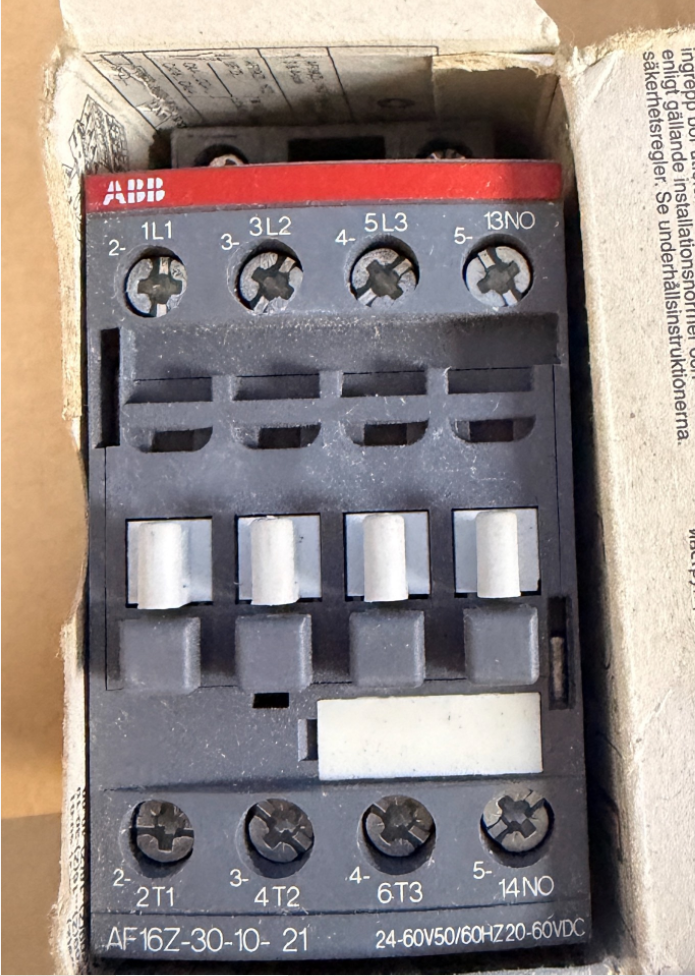

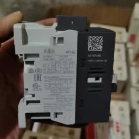
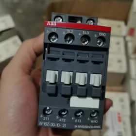
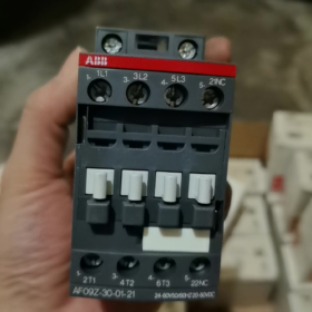
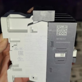
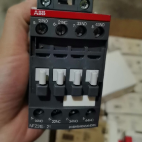
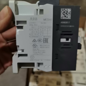
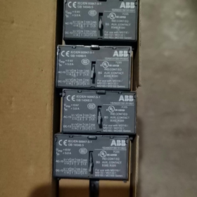
Original Factory Order No.: 1SBL176001R2110
- Определение разбивки модели
AF16Z 30 10 21
- AF16Z: серия АФ; Z = Low-power electronic wide-range coil (direct PLC drive capable); Размер кадра 16 сорт
- 30: Основные контакты: 3 Нормально открытый (3НЕТ), no main Normally Closed contacts
- 10: Встроенные вспомогательные контакты: 1 Нормально открытый (1НЕТ), 0 Нормально закрытый
- 21: Coil code → Control voltage: 24~60 V AC 50/60Hz / 20~60 V DC
⚠️ Difference between AF…Z and standard AF: Extremely low coil power consumption, supports direct driving by DC24V PLC outputs, resistant to voltage dips (compliant with SEMI F47).
- Основные электрические характеристики
Максимальное напряжение главной цепи: 690 В и
АС-1 (резистивная нагрузка), ≤40°C ambient: 30 А
АС-3 (3-фазовый двигатель, 400 В): 18 А, подходит для 7.5 кВт двигатель
АС-3 (690 В): 10.5 А, Макс. 9 кВт
Монтаж: Монтаж на DIN-рейку, винтовое клеммное соединение
Габаритные размеры: Вт 45 мм × В 86 мм × Г 77 мм
Рабочая температура: -40~+70 °C (without thermal overload relay); -25~+60 °C (with thermal overload relay)
- Key Coil Characteristics
Wide-range AC/DC universal: AC 24~60 V / DC 20~60 V
Built-in surge suppression; no external RC snubber or diode required
Low holding power consumption, ideal for continuous energized operation
Выдерживает кратковременные колебания напряжения и перепады напряжения.
- Идентификация терминала
Главная цепь: 1Л1-2Т1, 3Л2-4Т2, 5Л3-6Т3
Вспомогательный контакт: 14НЕТ (Нормально открытый)
- Общие альтернативы & Отличия
- АФ16З-30-10-11: Тот же диапазон напряжения, оснащен стандартной катушкой AF (не маломощная катушка Z); не может напрямую управляться слаботочными выходами ПЛК, не взаимозаменяемый.
- АХ16-30-10: Эконом-серия AX, без электронной широкодиапазонной катушки, фиксированное управляющее напряжение; не может заменить AF16Z.
- За 1НО + 1Вспомогательные контакты НЗ: Выберите модель AF16Z-30-11-21.
- Типичные применения
Перед преобразователями частоты, фанаты & водяные насосы, климатическое оборудование, полупроводниковое оборудование, ПЛК выход постоянного тока, прямое управление нагрузкой, промышленные объекты, требующие высокой устойчивости к колебаниям напряжения.
АББ АФ16З-30-10-21 Контактор Технический документ по установке
Заказ №.: 1SBL176001R2110
- Общие инструкции по безопасности
⚠️Вся установка, электромонтажные работы и работы по техническому обслуживанию должны выполняться при отключенном питании.; процедура блокировки-маркировки обязательна. Работы должны выполнять только квалифицированные электрики..
- Класс защиты: IP20. Только для установки в шкаф. Не устанавливайте на открытом воздухе, влажная среда, locations with heavy dust or corrosive gas exposure.
- Применимые стандарты: МЭК/EN 60947-1, МЭК/EN 60947-4-1; UL/CSA certified.
- AF16Z is equipped with a low-power electronic wide-range coil with integrated surge suppression circuit. No external RC snubber or diode connection is required.
- Основная информация о продукте
2.1 Определение модели
AF16Z: серия АФ, размер кадра 16, Z = low-power electronic coil
30: 3 нормально разомкнутые главные контакты
10: Встроенный 1 нормально открытый вспомогательный контакт
21: Coil voltage range AC 24~60 V 50/60Hz / DC 20~60 V
2.2 Габаритные размеры
Ширина 45 мм × Высота 86 mm × Depth 77 мм
2.3 Rating Summary Table
| Элемент | Параметр |
| АС-1 резистивная нагрузка (40 째C) | 30 А |
| Нагрузка двигателя AC-3 (400 В) | 18 А, совместим с 7.5 kW 3-phase motor |
| Максимальное рабочее напряжение | 690 В и |
| Рабочая температура (without thermal relay) | -40 째C ~ +70 째C |
| Рабочая температура (with thermal overload relay) | -25 째C ~ +60 째C |
- Технические характеристики механической установки
3.1 Способы монтажа
Two mounting options available:
- Монтаж на DIN-рейку (Рекомендуется)
Rail standard: TS35 (35×7.5 mm / 35×15 mm)
Операция: Hook the bottom latch onto the rail, press down until an audible click confirms locking. For removal, use a flat screwdriver to pry the bottom latch and lift upwards.
- Base Plate Screw Mounting
Fasten diagonally using 2 × M4 screws; refer to outline drawing for mounting hole spacing.
3.2 Монтажная ориентация & Распродажа
- Вертикальный монтаж (клеммы сверху & нижний) предпочтительный. 90° допускается горизонтальный боковой монтаж; установка в перевернутом положении запрещена.
- Несколько устройств могут быть установлены рядом без снижения тока.. Поддерживайте вертикальный зазор ≥15 мм для вентиляции.; держитесь подальше от компонентов, выделяющих тепло, таких как резисторы и инверторы.
- Избегайте установки в местах с высокой вибрацией.. Виброускорение >0.5g требует принятия мер по гашению вибрации.
- Характеристики электропроводки
4.1 Определение маркировки клемм
Верхняя главная цепь: Л1, Л2, Л3 (Вход питания)
Нижняя главная цепь: Т1, Т2, Т3 (Загрузочная розетка)
Приложения, не соответствующие требованиям UL, допускают подачу питания сверху или снизу.; Установки, сертифицированные UL, требуют подачи питания от верхних клемм L..
Клеммы катушки A1, А2: Вход управляющего сигнала (AC/DC неполяризованный)
Вспомогательный контакт 13-14: Встроенный нормально открытый контакт. (1НЕТ)
4.2 Спецификация кабеля & Длина зачистки
Стандартная длина зачистки провода: 10 мм
Проводники главной цепи: Одножильный/многожильный медный кабель 1~6 мм²; наконечники, рекомендуемые для гибких кабелей
Контроль / проводники вспомогательной цепи: 0.75~2,5 мм²
4.3 Момент затяжки (Обязательный)
Клеммы главной цепи: 1.5 Н·м
Катушка А1/А2 & вспомогательные контактные клеммы: 1.2 Н·м
Недостаточный крутящий момент приводит к перегреву клемм.; чрезмерный крутящий момент приводит к сорванию резьбы.
Рекомендуемые инструменты: Отвертка PZ2 Pozidriv / 5.5 плоская динамометрическая отвертка мм..
- Замечания по применению критически важных катушек (Основная особенность AF16Z)
- Диапазон напряжения: 24 ~ 60 В переменного тока / 20~60В постоянного тока, широкая совместимость по напряжению, прямой привод от выходов постоянного тока ПЛК.
- Очень низкое энергопотребление при удержании катушки., подходит для длительной работы под напряжением; соответствует требованиям SEMI F47 по устойчивости к провалам напряжения.
- A1 и A2 неполяризованы.; полярность не имеет значения для управления DC24V.
- Не подавайте управляющее напряжение, превышающее 60 В, в противном случае модуль электронной катушки будет разрушен..
- Установка дополнительных аксессуаров
- Боковые вспомогательные контакты (Серия CA4)
Защелкивается в левых/правых боковых пазах без инструментов.. Максимум 2 на AF16 можно установить наборы боковых вспомогательных контактов.
- Механическая блокировка
Установите для реверсивной конфигурации цепи два контактора AF16Z, чтобы предотвратить одновременное замыкание и короткое замыкание между прямой и обратной фазами..
- Согласование теплового реле перегрузки
Совместим с тепловыми реле серии TA25DU., прямой монтаж с защелкиванием под контактором.
- Процедура ввода в эксплуатацию после включения питания
- В выключенном состоянии: Визуальный осмотр правильности подключения, без металлического мусора, все клеммы затянуты с указанным моментом затяжки.
- Вручную активируйте контакторный механизм, чтобы убедиться в плавности работы без заклинивания..
- Проверить цепь управления самостоятельно: Подайте номинальное управляющее напряжение на A1/A2.; Контактор должен надежно включаться и плавно отключаться при отключении питания..
- Проверьте синхронность переключения вспомогательного контакта. 13-14 с контакторным управлением.
- Подключите силовую цепь для тестового запуска без нагрузки.; проверьте наличие ненормального шума и быстрого повышения температуры клемм..
- 30-минутный тест на работу под нагрузкой; еще раз проверьте температуру терминала, чтобы убедиться, что повышение температуры остается в допустимых пределах..
- Ошибки установки & Запрещенные действия
❌ Запрещенные операции:
Открытые свободные жилы на кабельных наконечниках
Затягивание клемм под напряжением
Управляющее напряжение вне диапазона 20~60 В.
Блокировка вентиляционных каналов над и под контактором
Непосредственная установка в средах с горючей пылью или постоянной конденсацией.
Распространенные проблемы после установки
- Контактор дребезжит/нестабильное втягивание: Убедитесь, что управляющее напряжение выше минимального рабочего уровня.; проверить падение напряжения на кабелях управления.
- Перегрев терминала: Затяните клеммы с указанным моментом затяжки.; убедитесь, что поперечное сечение проводника соответствует требованиям.
- Невозможность втягивания при управлении от ПЛК.: Подтвердите, что устройство AF16Z. (маломощная катушка); стандартная катушка AF16 не может напрямую управляться транзисторными выходами ПЛК.
- Требования к техническому обслуживанию
- Периодическая проверка температуры терминала и аномального шума.
- Избегайте повторных переключений, превышающих номинальную отключающую способность..
- Никогда не эксплуатируйте контактор со снятой дуговой защитой.. Замените весь блок, если контакты подверглись серьезной абляции..
Механические параметры ресурса ABB AF16Z-30-10-21
AF16Z имеет идентичную механическую конструкцию со стандартным AF16.. Официальные технические данные:
✅ Механическая выносливость: 10 миллионов рабочих циклов (10×10⁶ операций)
Условия испытаний: Номинальное управляющее напряжение, переключение без нагрузки, стандартная температура окружающей среды.
Поддержка ключевых параметров
- Максимальная механическая рабочая частота: 3,600 операций в час
Непрерывная высокочастотная работа не должна превышать этот предел во избежание ускоренного механического износа..
- Эталонная электрическая выносливость (зависит от типа нагрузки, не равен механической жизни)
АС-3 (400 V нагрузка двигателя): Приблизительно. 1,000,000 циклы
АС-1 (резистивная нагрузка): Приблизительно. 1,600,000 циклы
⚠️ Механическая износостойкость представляет собой механический предел эксплуатации.; Срок службы в практическом применении обычно определяется электрической эрозией контактов..
Дополнительные замечания
- AF16Z отличается только вариантом маломощной электронной широкодиапазонной катушки.. Арматура, Механическая конструкция соединения и контактов идентична стандартной AF16.; механическая выносливость остается неизменной.
- Фактическая механическая износостойкость снижается в суровых условиях эксплуатации. (тяжелая пыль, постоянная вибрация, высокая температура).
- Определение механической выносливости: Рабочие циклы включения/выключения контактора, управляемые только катушкой, без нагрузки, подключенной к главной цепи.










NH42-63-318x560.png "Автоматические переключатели резерва типа PC CHINT (АТС)НХ42-63/4СЗ")



