 Контактор,автоматический выключатель,датчик,Кодер,ПЛК,Конвертер





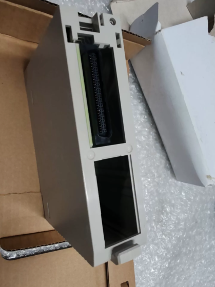
Полное название продукта: ОМРОН SYSMAC CQM1 Series PLC AC Блок питания
Статус: Снято с производства (March 2019). No genuine new stock available from manufacturer, and no official direct replacement model. Supplies on the market are mainly used dismantled units and refurbished parts.
Compatible Host: CQM1 / CQM1H series compact modular ПЛК. DIN rail mounted, installed at the far left of the rack to supply power to Процессор and I/O modules.
- Основные электрические характеристики
| Элемент | Параметр |
| Номинальное входное напряжение | 100~240V AC, 50/60Гц |
| Диапазон рабочего напряжения | 85~265V AC (Wide-range input) |
| Internal Output | 5В Вашингтоне: 3.6А (18Вт). No built-in 24V DC sensor power supply (differentiated from PA206/PA216) |
| Монтаж | DIN-рейка, assembled on the left side of CQM1 rack |
| Индикатор | ВЛАСТЬ (Power Run LED); lights up under normal power; extinguishes on power loss or overload |
| Защита | Перегрузка по току, защита от перенапряжения; cuts off 5V output upon fault to protect CPU and I/O modules |
Comparison with power supplies in the same series
CQM1-PA203: 5V@3.6A, low capacity, no 24V DC output
CQM1-PA206: 5V@6A, with 0.5A 24VDC auxiliary output
CQM1-PA216: Higher power AC power supply
CQM1-PD026: DC input power supply unit
- Определение кода модели
CQM1: Код серии (SYSMAC CQM1 compact PLC)
Пенсильвания: Power AC, AC input power supply unit
203: Specification revision code, denotes wide-range AC input with 5V 3.6A power rating
- System Selection Guidelines
- Total 5V current consumption of all modules (Процессор + ввод/вывод + специальные модули) must be ≤3.6A. Excessive load will cause frequent power dropout and power supply damage. Sum the 5V power consumption of each unit during selection.
- Modules are powered via backplane bus. External 5V cannot feed the backplane. Power can only be supplied by this power unit.
- No 24V sensor power terminals. Sensors on site require an independent external 24V power supply.
- Поиск неисправностей (Key Points for Used Units)
The most common failure mode of CQM1-PA203 is aging and bulging of internal electrolytic capacitors, a typical defect for this legacy power supply.
Симптомы: POWER LED does not light up after power-on; LED flashes or restarts repeatedly seconds after energization; voltage drops under load while voltage is normal at no load, power fails once CPU is fitted.
Инспекция: Disconnect all CPU/I/O modules, power up independently and measure backplane 5V output. If 5V is normal at no load but voltage collapses under load, capacitor aging is highly likely.
Acceptance checklist for second-hand units: Inspect PCB for swollen capacitors, burn marks and terminal corrosion; perform full-load aging test.
- Варианты замены (System Retrofit)
No pin-compatible new unit from OEM. Two available solutions:
- Refurbishment / Second-hand Replacement: Retain existing CQM1 platform. Purchase used CQM1-PA203, replace capacitors and run load test. Suitable for short-term equipment life extension.
- Full Machine Upgrade: Migrate the entire PLC system to CJ2M series (CJ2M-CPU + CJ2M power supply). Program migration is required; racks and all modules need replacement. This is a project-level modification for long-term stable operation.
- Сценарии применения
Legacy machine tools, упаковочное оборудование, textile equipment and old production lines equipped with OMRON CQM1/CQM1H compact PLC.
CQM1 → CJ2M Full System Migration: Hardware List & Program Migration Checklist
Reference OMRON official manual P087-E1-03 (CQM1(ЧАС) to CJ2M)
Основная предпосылка: CQM1 rack, backplane and power supply (CQM1-PA203) must be discarded and cannot be reused. CJ2M adopts CJ series backplane-less snap-together module architecture.
- Hardware Selection List (By Module Category)
1.1 Выбор процессора (Match Original CQM1 Program Capacity & I/O Points)
| Оригинальная модель | Recommended CJ2M CPU | Примечания |
| CQM1-CPU11/21 (5К шагов) | CJ2M-CPU11 | 5К шагов, базовый тип, USB+RS232 |
| CQM1-CPU41/42 (10К шагов) | CJ2M-CPU12 | 10К шагов |
| CQM1-CPU51/61 (20К шагов) | CJ2M-CPU13 | 20К шагов |
| Ethernet required | CJ2M-CPU31/32/33 | Встроенный Ethernet/IP |
Spares: CJ1W-BAT01 battery (for D/HR memory retention); end plate CJ1W-TER01 (must be installed at the rightmost of rack, otherwise error occurs)
1.2 CJ Series Power Supply (Replaces CQM1-PA203)
CJ1W-PA202: 100-240 В переменного тока, 5V 5A (наиболее часто используемый)
CJ1W-PA205R: Широкий вход переменного тока, 5V 10A for high-power systems
Mounting sequence: Power supply → CPU → I/O / Special modules → End plate
1.3 I/O Module Replacement (CQM1 Modules Cannot Plug into CJ Rack)
| Old CQM1 Module | CJ Series Equivalent | Примечания |
| CQM1-ID212 16-point DC Input | CJ1W-ID211 | 16-point DC24V input |
| CQM1-OD212 16-point Transistor Output | CJ1W-OD211 | 16-точечный транзисторный выход |
| CQM1-OC222 16-point Relay Output | CJ1W-OC211 | Релейный выход |
Fast Wiring Option: CJ1W-AT4xx terminal adapter. Mount original CQM1 terminal block directly onto CJ1W I/O modules, no need to re-crimp field cables. Недостаток: increased module depth; reserve space inside DIN cabinet.
1.4 Special Modules / Bus Module Replacement (Critical Pitfalls)
- Analog modules (CQM1-MAD01/MAD02 etc.) → CJ1W-MAD42, CJ1W-DA041; Unit number needs re-dip switch setting, CIO channel addresses will change.
- CQM1-B7A Remote I/O: B7A protocol not compatible with CJ2M. Master station and all remote slaves must be replaced with CompoNet (CJ1W-CRM21). All remote cables need rework; heavy workload.
- Коммуникационные модули: CQM1-SCB41 → CJ1W-SCU21-V1 serial module; DeviceNet CQM1-DRM21 → CJ1W-DRM21.
1.5 Rack & DIN Rail Accessories
CJ series uses no backplane; modules snap together directly.
Максимум 10 units for single CPU rack; expansion racks use CJ1W-IC101 (CPU rack side) + CJ1W-II101 (expansion side). До 3 стойки расширения.
1.6 Hardware Test Tool List
CX-программист (V9.5+ recommended), USB programming cable (CJ2M with built-in USB port)
Мультиметр, 24В источник питания, terminal jumpers, принтер этикеток
PC with backup of original program
- Program Migration Checklist (CX-Programmer Migration Workflow)
Core note: CX-P can auto-convert most ladder logic, but address mapping, some instructions and flags may fail. Converted project cannot be downloaded directly for production.
✅ Phase 1: Pre-migration Preparation (Before Shutdown)
- Upload complete CQM1 program, I/O comments, initial values of D/HR memory and PLC system settings online; keep two separate backups.
- Record original system information:
Slot position of each module, unit number (DIP switch settings of special modules)
CIO channel assignment (вход, выход, channels allocated to special modules)
Параметры связи: serial / DeviceNet baud rate, station number
Interrupt program, high-speed counter, pulse output parameters
Current values of D, HR, AR, TIM/CNT in original PLC
- List special instructions, ПИД, high-speed counter and interrupt instructions used in original program.
- Export I/O address table and create old-to-new address comparison sheet (most critical document).
✅ Phase 2: CX-P Model Conversion Procedure
- Open CQM1 project in CX-P → PLC → Change Model, select corresponding CJ2M CPU model.
- Software auto-converts instructions; check conversion errors and warnings in output window.
- Ключ: Memory Map Correction (CQM1 vs CJ2M Memory Differences)
CQM1: Fixed CIO allocation; CJ2M: Basic I/O units auto assigned CIO 0000~0159CH; Special I/O units: 2000~2959CH, 10CH per unit; CPU bus units 1500~1899CH, 25CH per unit. Allocation rules differ.
Manually reassign CIO to match original CQM1 channel mapping, otherwise all I/O will be misaligned.
AR area (auxiliary relay) address definitions differ. AR flags are a frequent source of faults.
- Item-by-item instruction verification (failed conversion or behaviour-changed instructions)
Operation operands of some BCD/BIN conversion instructions are changed;
Interrupt instructions: Legacy CQM1 interrupt instructions must be rewritten in CJ2M using MSKS / MSKR / интерфейс командной строки / EI / ОТ;
PID instruction parameter structure differs;
Carry and zero flags (P_Flag) behave differently after execution of certain instructions, causing hidden logic faults without compile errors.
- Data memory migration:
After model conversion, D and HR values are not inherited automatically. Manually copy initial values between CQM1 memory window and CJ2M memory window. Verify preset values of TIM/CNT.
- PLC System Settings:
Cycle time, interrupt response, serial parameters, battery detection, power-up mode;
CJ2M system setting pages are completely different from CQM1; old settings cannot be reused.
✅ Phase 3: Сборник, Simulation & Offline Debugging
- Full compilation, clear all Errors; Evaluate all Warnings one by one, do not ignore.
- Offline simulation: Force I/O status to test logic branches, таймеры, counters and alarm logic.
- Проверять: Old/new I/O address table, special module channels, communication addresses.
- Document update: Update program comments, electrical drawings and I/O table.
✅ Phase 4: Hardware Power-up & Online Debugging (Step-by-Step Safe Procedure)
- Power off and assemble full CJ2M hardware. Verify module order, DIP switch settings and end plate installation.
- No-load power-up (disconnect field actuator outputs):
Check power supply and CPU RUN LED; confirm no I/O or unit errors;
Download program + PLC settings + D area initial values;
Force input points and check CIO input status; force outputs and measure terminals.
- Power on with sensors: Verify all DI input signals.
- Single-point test of DO outputs without load.
- Single-point test of special modules: аналоговый, high-speed counter, pulse output.
- Тест связи: serial port, bus and HMI/host computer communication.
- Full machine no-load sequence test, monitor scan cycle time.
⚠️ CJ2M executes instructions faster, scan cycle is shorter, which may trigger timing-dependent issues on original CQM1 logic (например. latch and delay logic). Timing validation is required; add software delay if necessary.
✅ Phase 5: Load Trial Run & Acceptance
- Loaded jogging and single-cycle operation;
- Continuous trial run, monitor alarms, memory and CPU error logs;
- Back up final CJ2M program and memory image; update equipment files;
- Prepare rollback plan (retain original CQM1 system as emergency backup).
- Migration Risk Checklist (Critical Pitfalls)
- ❗ Different CIO allocation mechanism: I/O address misalignment even if compilation passes, leading to unintended machine movement.
- ❗ Behaviour difference of flags (P_On, P_Off, P_CY, P_EQ), hidden logic bugs hard to detect via simulation.
- ❗ CQM1-B7A remote I/O cannot be reused; full replacement required.
- ❗ Shorter scan cycle introduces timing issues; many legacy logics rely on slower scan speed of old PLC.
- ❗ Memory loss on battery replacement for CJ2M: D area data will be lost when replacing battery with power off. Complete data backup is mandatory.
- ❗ Space interference with CJ1W-AT4xx adapter; CPU USB port may be blocked. Verify cabinet depth in advance.
- Deliverable List After Migration Completion
- Full CJ2M CX-P project (with comments and I/O table)
- Old-to-new I/O address comparison sheet
- D/HR memory initial value backup file
- Updated hardware wiring diagram with CJ module terminals
- Module DIP switch table and communication parameter document
- Test log and trial run report
- Troubleshooting manual
- Comparison of Optional Simplified Solutions
Вариант А (Full migration to CJ2M): Long-term stable solution. Higher cost, longer downtime and heavy program modification.
Вариант Б (Only repair CQM1-PA203 power supply, keep original PLC system): Low cost for rapid life extension. However CPU and other modules remain aged, only suitable for short-term transition.





NH42-63-318x560.png "Автоматические переключатели резерва типа PC CHINT (АТС)НХ42-63/4СЗ")



