 Контактор,автоматический выключатель,датчик,Кодер,ПЛК,Конвертер

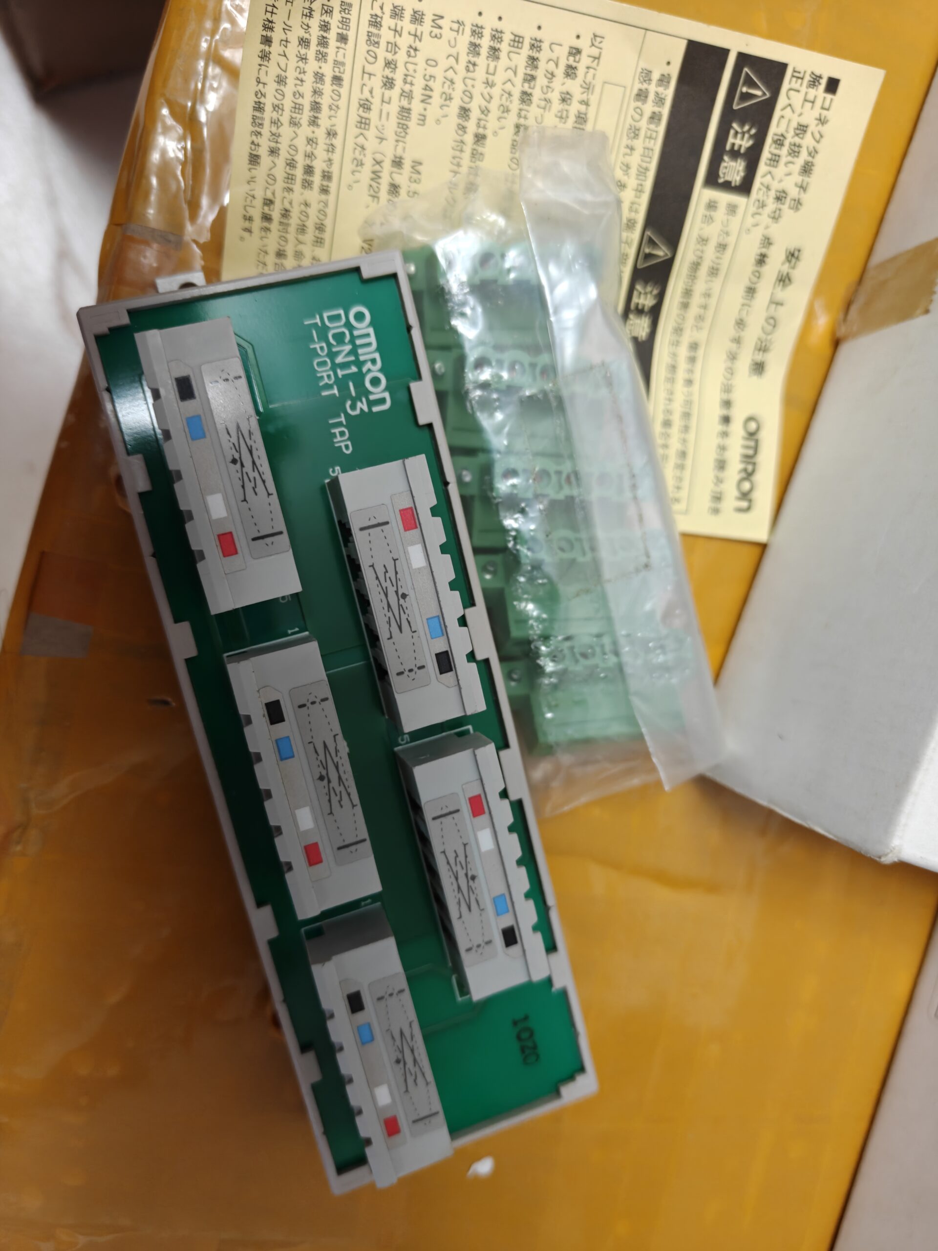

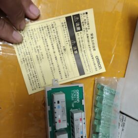
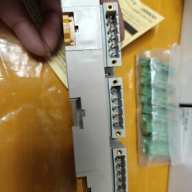
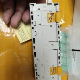
DCN13 is the common market name; the full official model designations are DCN13C / DCN13NC. It is a Tbranch tap dedicated for DeviceNet thickcable fieldbus, используется для разделения 3 dropline nodes from the trunk line. It comes with a builtin 120 Ω terminating resistor and belongs to OMRON DeviceNet peripheral accessories.
Разбивка кода модели
| Модель | Suffix Definition | Cable Routing Direction | Mating Connector |
| DCN1‑3C | C = Side‑outlet | Cable exits horizontally | XW4B‑05C1‑H1‑D (5 шт.) |
| DCN1‑3NC | NC = Top‑outlet | Cable exits upward | XW4G‑05C1‑H1‑D (5 шт.) |
DCN1:DeviceNet TBranch Tap
3:Максимум 3 branch outputs
С / Северная Каролина:Physical cable outlet direction; mechanical difference only, electrically identical.
Основные характеристики оборудования
| Элемент | Технические характеристики |
| Bus Protocol | Девайснет (CAN‑based), thick‑cable trunk branching |
| Branch Quantity | 3 branch interfaces, 1‑in / 1‑out trunk pass‑through |
| Built‑in Terminating Resistor | 120 Ой (configurable ON/OFF; terminators must be fitted at both physical ends of the trunk) |
| 5‑Pin Pinout | 1: V‑; 2: CAN_L; 3: DRAIN Shield; 4: CAN_H; 5: В+ |
| Тип разъема | Screw‑clamp parallel connector, for DeviceNet thick cable |
| Момент затяжки | 0.25‑0.3 N·m, dedicated screwdriver XW4Z‑00C |
| Сертификаты | UL, CE |
| Рабочая температура | 0‑60 °C; Хранилище:‑25‑85 °C, конденсация запрещена |
| Монтаж | Монтажные отверстия М3; DIN‑rail mounting not supported, panel‑screw mounting to cabinet backplate only |
Wiring Logic
- Connect the upstream trunk bus to the IN port of DCN13; connect the OUT port to continue the downstream trunk.
- Connect DeviceNet slavedevice droplines to the 3 branch ports.
- 120 Ω terminating resistors must only be fitted at the two physical extreme ends of the entire trunk bus. The builtin resistor of this tap shall be ENABLED only when this tap sits at the physical bus end. For all intermediate nodes, the builtin terminator MUST be disabled. Otherwise abnormal network resistance occurs (normal network resistance range: 5070 Ой).
⚠️Fault symptoms: Network errors, slaves not detected. Prioritize troubleshooting: duplicate terminators, shieldgrounding, CAN_H/CAN_L polarity reversal.
Полный список серий
| Модель | Branch Count | Outlet Direction |
| DCN1‑1C / DCN1‑1NC | 1 branch | Сторона / Вершина |
| DCN1‑2C / DCN1‑2R | 2 branches | Сторона / Right‑angle |
| DCN1‑3C / DCN1‑3NC | 3 branches | Сторона / Вершина |
| DCN1‑4C / DCN1‑4R | 4 branches | Сторона / Right‑angle |
| DCN1‑1P | Power tap (with fuse) | ‑ |
EndofLife & Информация о замене
- DCN13C / 3NC are EOL (EndofLife). The DeviceNet ecosystem is gradually phased out; OMRON provides no direct pintopin replacement model.
- OMRONrecommended migration options:
ВариантА: Stack multiple DCN11C (1branch) taps to realize multibranch topology.
Вариант Б: DCN311 sealed Tconnector (for M12 thincable systems).
- Thirdparty compatible alternatives: Aftermarket replicas of DCN13C are available. Verify mating connector dimension (XW4B05C1H1D), switchable 120 Ω terminator and thickcable compatibility before purchase.
Типичные сценарии применения
Automotive welding lines, materialhandling sorting lines, литьевые машины. OMRON CS/CJseries PLC DeviceNet masters (C200HWDRM21V1 / CJ1WDRM21) networking with DRTseries remote I/O modules; multibranch slavenode deployment over thickcable trunk.
Selection PitfallAvoidance Guidelines
- ❗Distinguish DCN1 thickcable series vs DCN3 thincable series: connectors are physically incompatible; do not intermix.
- ❗Never enable the builtin terminator for intermediate bus nodes; only enable terminators at the two physical trunk ends.
- ❗Use DeviceNetspecific 5core shielded cable only. Generic CANbus cable has mismatched impedance and causes communication packet loss.
- ❗Observe strict tightening torque 0.250.3 N·m. Excessive torque damages cable conductors; insufficient torque causes unstable communication.
Appendix 1: DCN1Series (ThickCable) DeviceNet Branch Tap Selection Table
| Модель | Branch Count | Outlet Direction | Switchable 120 Ω Terminator | DIN‑Rail Mount | Типичное использование |
| DCN1‑1C | 1-способ | Сторона | Да | ❌ Screw‑mount only | Single‑point branch for intermediate bus node |
| DCN1‑1NC | 1-способ | Вершина | Да | ❌ Screw‑mount only | Top‑exit wiring for compact cabinet space |
| DCN1‑2C | 2-способ | Сторона | Да | ❌ Screw‑mount only | Near‑site branching for 2 slaves |
| DCN1‑2R | 2-способ | 90° Right‑angle | Да | ❌ Screw‑mount only | Right‑angle routing along cabinet sidewalls |
| DCN1‑3C | 3-способ | Сторона | Да | ❌ Screw‑mount only | Common‑name DCN1‑3; centralized branching for 3 узлы |
| DCN1‑3NC | 3-способ | Вершина | Да | ❌ Screw‑mount only | 3‑node application with upward cable routing |
| DCN1‑4C | 4-способ | Сторона | Да | ❌ Screw‑mount only | Centralized breakout for 4 slave devices |
| DCN1‑4R | 4-способ | 90° Right‑angle | Да | ❌ Screw‑mount only | High‑density right‑angle wiring |
| DCN1‑1P | 1‑way Power tap | Сторона | Нет | ❌ Screw‑mount only | Bus power tap with built‑in fuse |
Важное примечание: DCN1 = thickcable system; DCN3 = M12 thincable system. Physical plug incompatibility; cannot be mixed within one trunk.
Appendix 2: DCN13 Troubleshooting Checklist
Network impedance reference: With terminators enabled at both trunk ends and all intermediate terminators disabled, bus impedance shall read 5070 Ω. Multiple enabled terminators drop impedance to ~30 Ω and trigger communication faults.
📋 HardwareWiring Verification
- Verify 5pin assignment (refer to pinout diagram):
Контакт 1: V Bus negative supply
Контакт 2: CAN_L
Контакт 3: SHIELD Drain
контакт 4: CAN_H
Pin 5: V+ 24 V bus supply
✅ Forbidden: CAN_H / CAN_L reversal; В+ / V polarity reversal — will destroy slave hardware.
- Terminal screw torque: 0.250.3 Н·м. Overtorque fractures conductors; undertorque creates intermittent contactrelated packet loss.
- Shieldhandling: Connect Pin 3 shield drain to ground at one single point only. Multiple grounding points create groundloop interference and frequent communication errors.
📋 TerminatingResistor Troubleshooting (Highestprobability fault source)
- Tapmount toggle switch: Enable the internal 120 Ω terminator ONLY if this tap sits at the absolute physical end of the DeviceNet trunk. Disable for all intermediate nodes.
- The entire trunk shall have exactly two terminators, fitted at the two physical trunk extremities.
- Multimeter measurement between CAN_H / CAN_L:
Terminator ON at both ends, all intermediate terminators OFF: 5070 Ω ✔ OK
Multiple terminators enabled: <40 Ω ❌ Fault
Both end terminators OFF: Infinite resistance ❌ Missing termination
📋 Fault Phenomena, RootCauses & Средства правовой защиты
| Явление неисправности | Probable Root‑Cause | Корректирующие действия |
| PLC fails to detect all slaves | Duplicate terminators; CAN_H/CAN_L reversed; loss of bus 24 V supply | Check terminator switches; validate pinout; measure V+/V‑ (21-24 В постоянного тока) |
| Random intermittent drop‑out of partial slaves | Poor crimp/torque; multi‑point shield grounding; cable‑impedance mismatch; routing adjacent to power cables | Retorque terminals; single‑point shield grounding; use genuine DeviceNet cable; separate from power‑cable runs |
| Slave hardware damaged immediately upon power‑on | Bus V+ / V‑ polarity reversed | Power‑off, validate pin 1 / pin 5 polarity; replace damaged slaves |
| Network scans OK, frequent I/O data errors | Drop‑line length exceeds specification; mixed thick‑/thin‑cable topologies | Max drop‑line length for thick‑cable trunk: 6 m. Do not connect DCN1 thick‑cable hardware directly to DCN3 M12 thin‑cable devices. |
⚠️ HardConstraint Prohibitions
- ❌ DINrail mounting is forbidden. Mount only via M3 screws to backplate.
- ❌ Generic CANopen cable cannot substitute DeviceNet cable; impedance mismatch.
- ❌ Individual dropline length must not exceed 6 m. Max trunklength vs baudrate: 500 kbps = 100 m; 250 kbps = 250 m; 125 kbps = 500 m.
- ❌ Never activate the tapinternal terminator when the tap is located at an intermediate cabinetbus node.
Appendix 3: EOL Upgrade Recommendations
DCN13C/DCN13NC are EOL; OMRON offers no dropin replacement.
- Retrofit Option 1: Deploy multiple DCN11C taps for distributed wiring while retaining the original thickcable infrastructure (spare parts still available).
- Retrofit Option 2: Fullsystem migration to DCN3series M12 thincable topology; all master/slave connectors must be replaced, high hardware modification overhead.
- Thirdpartycompatiblepart procurement notes: Confirm pinassignment, switchable 120 Ω terminator, compatibility with DeviceNet thickcable conductor gauge.
OMRON DCN13 (DCN13C / DCN13NC) Сценарии применения
DCN13 is a DeviceNet thickcable Tbranch tap with 3 branch outputs. Core value: derive three droplines from one single location on the thickcable trunk for remote I/O, датчики, drives and other slavedevices. Optimized for centralized multinode breakout inside machines / шкафы управления. Strictly for thickcable trunk systems; incompatible with DCN3 M12 thincable hardware.
Typical IndustryUse Cases
- Automotive WeldingProduction Lines (Mostcommon deployment)
Network architecture: OMRON CJ1WDRM21 / CSseries PLC as DeviceNet master; thickcable trunk routed along welding stations.
DCN13 usage: One station hosts three DRTseries remote I/O, valve islands or welding controllers. One DCN13 provides three local droplines, eliminating cascaded multiple Ttaps and reducing total busconnector count and communicationfailure points.
Ограничения: Each individual dropline ≤ 6 m. Tap secured to stationcabinet backplate with M3 screws.
- MaterialHandling & Conveyor Systems
Оборудование: Roller conveyors, sorting transfer mechanisms, blocking cylinders, photoelectric detectors.
Приложение: A trunkline passes beside a sorting shuttle / transfer unit with three concurrent remoteI/O nodes. DCN13 implements centralized branching for DR2 / DRT DeviceNet slaveI/O modules.
Преимущество: Reduces internalcabinet cable clutter compared with multiple DCN11 singlebranch taps.
- InjectionMolding & Extrusion Machinery
сеть: DeviceNet bus inside molding machine connects temperatureinput modules, proportionalvalve drives and safetyinput modules.
Placement: Inside control cabinet trunkrouting; local branching for three colocated slavedevices.
Примечание: Highelectricalnoise environment inside injectionmachines. Shield drain must be singlepointgrounded; multipoint grounding prohibited.
- Упаковочное оборудование (Еда & Фармацевтическая упаковка)
Machines: Case packers, паллетайзеры, запечатывающие машины.
Сценарий: Three sets of DeviceNet slaves (valve islands, detection I/O) grouped on one cabinet side; DCN13 for concentrated dropline breakout.
Экологические ограничения: Operating temperature 060 °C. Not suitable for heavycondensation or corrosiveatmosphere environments.
- MachineTools & CustomBuilt SpecialPurpose Automation Machines
Fixtureandtooling workstations: Three signalacquisition slavenodes at one workstation where the thickcable trunk passes by. DCN13 for local branching.
Примечание: Prevent direct exposure to machinetool cutting fluid; install inside protective enclosure.
Cabinetlevel / Machinemount Topology Scenarios
- Centralized branching inside control cabinet
DeviceNet thickcable trunk runs through cabinet. Three slavemodules reside inside cabinet. DCN13 fastened to cabinet backplate: IN for upstream trunk, OUT continues downstream trunk; three branch ports connect to three slavedevices.
When DCN13 is not at the physical trunk end: internal 120 Ω terminator must be OFF.
- Mounted inside fieldjunction box
Trunkcable enters a fieldrated junctionbox; three droplines route out to field valveislands / Модули ввода-вывода. Tap itself has no IPrating; must be fully enclosed within protective junctionbox, never exposed outdoors.
NonApplicable Scenarios (Selection Warnings)
- ❌ DeviceNet thincable (М12) системы: DCN13 is thickcableonly, hardware incompatible with DCN3series; do not intermix.
- ❌ Trunkend location requiring only 12 узлы: Prefer DCN11C / DCN12C, avoid overspecifying DCN13.
- ❌ Individual dropline length > 6 m: DeviceNet thickcable dropline hardlimit; excess length destabilizes network.
- ❌ Outdoor installation, direct fluid spray, heavy condensation, агрессивная атмосфера.
- ❌ Direct DINrail mounting: No DINclip hardware; only M3 panelscrew mounting allowed.
- ❌ CANopen bus usage: Similar physical connector, protocollayer incompatible; cannot operate on CANopen networks.
Reference BillofMaterial for Matching Hardware
PLC Master Units: CJ1WDRM21, C200HWDRM21V1
Slave I/O: DRT2ID, DRT2OD, DRT2MDseries remote I/O
Valve Islands: SMC DeviceNet valveisland, Festo DeviceNet valveisland
Кабель: DeviceNetspecific 5core shielded thickcable
OMRON DCN13 (DCN13C / DCN13NC) Инструкции по установке
⚠️ Критический: DCN13 has no DINrail clip. Direct DINrail mounting is unsupported. Panelscrew mounting only.
- Технические характеристики механической установки
| Элемент | Ценить |
| Тип монтажа | Panel‑mount to cabinet backplate / mounting panel |
| Монтажные отверстия | 2 × Φ3.5 mm through‑holes for M3 screws |
| Recommended Fasteners | M3 pan‑head screws |
| Device‑body tightening torque | 0.4‑0.5 N·m. Do not over‑tighten to avoid housing cracking. |
| Габаритные размеры (DCN1‑3C) | 142(л) × 45(Вт) × 31.3(Д) мм |
| Монтажная ориентация | Arbitrary (горизонтальный / вертикальный). Reserve sufficient clearance for cable‑handling and screwdriver access. |
MechanicalRouting Difference: DCN13C vs DCN13NC
- DCN13C (C = Sideoutlet)
Cables exit horizontally from unit side. Suited for flatmounting on cabinet backplate with horizontal cablerouting.
- DCN13NC (NC = Topoutlet)
Cables exit vertically upward from unit top. Used when installationlocation has limited bottomside clearance.
Electrical performance is identical; selection purely depends on fieldcablerouting geometry.
- Standard Installation Procedure
- Drill two Φ3.5 mm mounting holes on cabinet backplate according to dimensional drawing.
- Fasten DCN13 body to cabinet backplate with M3 screws; torque 0.40.5 N·m.
- Reserve clearance all around for connector access and screwdriver operation.
- Terminate DeviceNet thickcables:
В: Upstream trunk bus; ВНЕ: Continue downstream trunk bus.
Remaining three ports connect droplines to respective slavedevices.
Connector terminal screw torque = 0.250.3 N·m. Overtorque damages cable strands; undertorque causes intermittent communication faults.
- Configure the builtin 120 Ω terminator toggle switch:
Tap located on intermediate bus node → Terminator OFF.
Tap located at absolute physical trunkbus end → Terminator ON.
- Shieldwiring: Контакт 3 (SHIELD/DRAIN) connected to protective earth at one single groundpoint only. Multiplepoint grounding prohibited to prevent groundloop noise.
- InstallationLocation Requirements
- ✅ Acceptable environments: Inside controlcabinet backplate; inside protective junctionbox; ambient temperature 060 °C, condensationfree.
- ❌ Forbidden installation conditions:
Direct DINrail mounting (strapping with cableties leads to vibrationinduced loosening and intermittent faults).
Exposed outdoor mounting, direct cuttingfluid spray.
Mounting in immediate proximity to VFDs, contactors and highpower components; maintain clearance for noise mitigation.
Sealed confined compartments leading to temperature rise above 60 °C.
- Hard TopologicalWiring Constraints (Must be followed for hardware installation)
- Maximum individual dropline length: 6 m absolute limit for thickcable system. Longer droplines degrade network stability.
- Trunkline maximum length vs baudrate:
500 кбит/с: 100 m max
250 кбит/с: 250 m max
125 кбит/с: 500 m max
- Exactly two 120 Ω terminators shall be enabled at the two physical trunkbus ends. All intermediatenode tap terminators shall remain disabled.
- Распространенные ошибки при установке & Pitfalls
- ❌ Securing unit to DINrail only with cableties: Vibration loosens assembly, triggers random network dropouts.
- ❌ Excessive terminalscrew torque: Conductor crushing creates latentintermittent faults.
- ❌ Multiplepoint shieldgrounding: Highfrequency communication errors and packet loss.
- ❌ Accidentally enabling builtin terminator when tap sits on intermediate cabinetbus node: Low network impedance.
- ❌ Dropline length exceeding 6 m.
- SpecialScenario Installation
Junctionbox mounting: Secure DCN13 inside IPrated junctionbox. The tap itself has no environmentalprotection rating and must never be exposed.
Compactsize cabinets: Prefer DCN13NC topoutlet model to reduce horizontalcable interference.





NH42-63-318x560.png "Автоматические переключатели резерва типа PC CHINT (АТС)НХ42-63/4СЗ")



