 Контактор,автоматический выключатель,датчик,Кодер,ПЛК,Конвертер


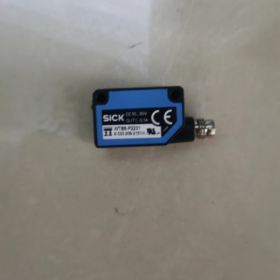
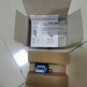
Straight 4m cable: YF8U14-040VA3XLEAX
Straight 5m cable: YF8U14-050VA3XLEAX
Connector base: STE-0804-Г (terminal block for control cabinet wiring)
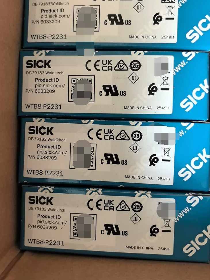
Полная установка & Commissioning Manual for SICK WTB8-P2231 Photoelectric Sensor (Order No.6033209)
- Основная информация о модели
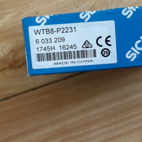
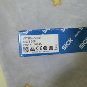
Complete Model No.: WTB8-P2231
Официальный приказ №.: 6033209
Ряд: W8 Ultra-compact Diffuse Фотоэлектрический датчик with Background Suppression
Источник: Китай
Стандартные аксессуары: Stainless Steel Mounting Bracket BEF-W100-A
Разбивка кода модели
- WT: Diffuse reflective photoelectric sensor
- Б: Equipped with background suppression function
- 8: W8 miniature housing (11×31×20mm)
- П: ПНП-выход
- 22: M8 straight 4-pin connector, red LED light source
- 31: 4-turn potentiometer adjustment, Свет включен / Dark-on switchable
- Core Optical Specifications
| Параметр Элемент | Спецификация |
| Принцип обнаружения | Диффузное отражение + подавление фона |
| Источник света | Видимый красный светодиод, 650нм |
| Standard Sensing Range | 40~300mm (90% high-reflective white paper) |
| Minimum Suppression Distance | 30мм (Filters background at close range) |
| Spot Size at 300mm | Φ20 мм |
| Метод регулировки | 4-turn precision potentiomsicketer |
| Режим работы | Switchable Light-on / В темноте |
III. Электрические характеристики
- Источник питания: DC 10~30V, ripple ±10%
- Выход: ПНП с открытым коллектором, Макс. load 100mA
- Ток покоя: ≤30mA
- Время ответа: ≤0.5ms
- Частота переключения: 1000Гц (for high-speed object detection)
- Защита: Обратная полярность, сверхток & тройная защита от короткого замыкания
- Срок службы: 100,000 hours for LED light source (25℃)
- M8 4-Pin Wiring Definition (Straight Connector)
Pin color & функция (industry standard 4-core cable):
- Б. Н. Браун: 24 В постоянного тока+ (Л+)
- Белый Белый: Unused pin (нет связи)
- БУ Синий: 0V Отрицательный (M/GND)
- БК Черный: PNP signal output Q
- Механический & Экологические характеристики
Размеры: W11mm × H31mm × D20mm
Масса: Only 10g
Материал корпуса: АБС-пластик; оптическое окно: ПММА
Класс защиты: IP67 (dustproof, temporary water immersion resistant)
Рабочая температура: -25℃ ~ +55℃
Температура хранения: -40℃ ~ +70℃
Монтаж: Fixed via symmetric M3 threaded holes on both sides
- LED Indicator Description
- Зеленый светодиод: Steady on = Normal power supply; Flashing = Unstable detection
- Orange LED: Illuminated = Sensor output activated (object detected)
VII. Основные преимущества
- Powerful Background Suppression: Eliminates interference from metal frames, конвейерные ленты, walls and other backgrounds, ensures stable detection for black & white workpieces
- Ultra-compact Size: Easy installation in narrow equipment, pipeline modules and robot grippers
- Высокая скорость отклика: Ideal for packaging, sorting and small parts counting
- IP67 dust & водонепроницаемость, stable operation in oily & humid workshop conditions
- 4-turn potentiometer enables high-precision fine-tuning for minor distance adjustments
VIII. Типичные сценарии применения
Presence detection of materials on packaging production lines
Подсчет & position confirmation of small hardware/plastic components
Leakage prevention detection of products on conveyor belts
Workpiece positioning inside electronic equipment
Sorting small items in logistics systems
- Альтернатива / Distinct Models in the Same Series
- WTB8L-P2231: Laser version with identical housing, smaller light spot for high-precision long-distance detection
- WTB8-N2231: Вариант вывода NPN (for PLC negative common input)
- WTB8-P1301: M8 elbow cable outlet, for space-limited installation
- WTB8-P2231V: Sanitary stainless steel housing (for humid food processing environments)
- Recommended Matching Cables
Оглавление
- Инструкции по безопасности
- Unboxing Standard Parts List
- Технические характеристики механической установки (Bracket, Крутящий момент, Размеры, Требования к разрешению)
- M8 4-Pin Electrical Wiring Definition & Процедуры подключения
- On-site Optical Alignment & Distance Adjustment Operations
- Свет включен / Dark-on Mode Switching
- LED Indicator Status Explanation
- Environmental Installation Prohibitions & Требования защиты
- Регулярное техническое обслуживание & Cleaning Standards
- Матрица устранения неполадок
- Selection of Matching Cables & Запчасти
- Mandatory Safety Instructions
- Cut off DC24V power supply before wiring. Hot plug/unplug of M8 connector is forbidden to avoid breakdown of output chip.
- Rated power supply range is limited to DC 10~30V; AC220V or AC110V input is strictly prohibited, which will burn the sensor instantly.
- Макс. output load is 100mA. Direct driving of solenoid valves or contactors is forbidden; add relay isolation if high-power loads need to be driven.
- Бурение, grinding or disassembling the sensor housing is prohibited. Damaged IP67 seal will result in loss of dustproof and waterproof performance.
- Prevent strong light from directly irradiating the optical window (sunlight, welding arc, high-power spotlights), which causes false triggering and detection failure.
- Avoid heavy impact or dropping; offset internal optical path will permanently degrade detection stability.
- Unboxing Standard Parts List
Sensor Main Unit: WTB8-P2231 ×1
Standard Mounting Accessory: BEF-W100-A stainless steel bracket ×1
Крепежные винты М3, flat washers & пружинные шайбы (supplied with bracket)
No factory-supplied cable; M8 4-pin straight cable shall be purchased separately
- Технические характеристики механической установки
3.1 Габаритные размеры
W11mm × H31mm × Depth 20mm; symmetric M3 internal threaded mounting holes on both sides.
3.2 Bracket Mounting Steps
- Secure BEF-W100-A bracket to equipment sheet metal or aluminum extrusion and pre-tighten screws.
- Clip the sensor into the bracket slot, align bilateral M3 holes, and pass through M3 bolt, flat washer and spring washer.
- Стандартный момент затяжки: 1.8 Нм
Недостаточный крутящий момент: Vibration causes sensor offset and light spot drift;
Чрезмерный крутящий момент: Зачистка резьбы, housing deformation and optical path misalignment.
- Fine-tune vertical & horizontal angles of the sensor to fully cover target surface with red light spot, then lock all bolts.
3.3 Installation Clearance Requirements (Critical for Background Suppression)
- Reserve a minimum clearance of 30mm between sensor optical window and fixed rear background; otherwise background interference leads to permanent false ON signal.
- Standard detection range: 40~300mm (90% high-reflective white object); 30~40mm is critical range susceptible to material interference.
- Do not place metal, mirror or high-reflective panels closely behind the sensor; intense diffuse reflection will disable background suppression.
- Pipeline installation: Align light spot to workpiece center, avoid conveyor joints, rollers and metal supports.
- Multiple sensors mounted side-by-side: Adjacent sensor spacing ≥50mm to prevent mutual red light crosstalk interference.
3.4 Permitted / Prohibited Installation Environments
✅ Permitted: Сухой цех, light dust, intermittent water spray (IP67 temporary water resistance), environment of -25℃~+55℃
❌ Запрещено: Continuous immersion, strong corrosive acid/alkali liquid, long-term cutting oil splash, temperature above +55℃ or below -25℃, areas beside heavy electromagnetic cabinets (инверторы, high-power motors)
- Характеристики электропроводки
4.1 M8 4-Pin Straight Connector Fixed Pin Definition
| Контактный номер. | Цвет провода | Функция | Инструкция по подключению |
| 1 | Б. Н. Браун | DC24V Positive L+ | Output terminal of switching power supply |
| 2 | Белый Белый | Unused Pin | Leave floating, do not connect to power or ground |
| 3 | БУ Синий | 0V Negative GND | Power negative & PLC common terminal |
| 4 | БК Черный | PNP Output Q | PLC digital input terminal (PNP high-level active) |
4.2 Этапы работы с проводкой
- Confirm power supply cut off, insert M8 connector straight into the slot at sensor tail, tighten thread clockwise without brute force.
- Route cables away from power cables and inverter output lines with separation ≥10cm to avoid electromagnetic interference.
- Cable bending radius ≥5× cable outer diameter; hard folding or long-term extrusion of cable root is forbidden.
- Fit a 4A slow-blow fuse in power circuit to protect sensor against short-circuit damage.
4.3 PNP Output Matching Instruction
Connect PLC input common terminal to 24V negative; connect black signal wire of sensor directly to PLC input point. No external pull-up resistor required.
- Optical Alignment & Distance Adjustment (4-turn Precision Potentiometer)
5.1 Alignment Operation
- После включения, green power LED stays steady; observe red light spot at front end.
- Adjust sensor angle to fully cover target workpiece without partial spot falling on background bracket.
5.2 Potentiometer Adjustment Flow (Background Suppression Calibration)
- Place target workpiece at maximum sensing distance (300мм), slowly turn potentiometer clockwise until orange output LED just lights up.
- Remove workpiece, orange LED must turn off; if it remains on, background interference exists — increase distance between sensor and background or fine-tune potentiometer counterclockwise.
- Repeat placing & removing workpiece for verification: LED lights when workpiece is present, extinguishes when absent, no frequent flashing means calibration completed.
- The potentiometer supports 4-turn adjustment with high fine-tuning precision; avoid excessive rotation each time.
- Свет включен / Dark-on Mode Switching
Small toggle switch on sensor side:
л (Свет включен): Output ON when light spot is blocked by object (orange LED illuminated), default mode for pipeline workpiece presence detection.
Д (В темноте): Output ON when no object exists; signal cut off when workpiece arrives, suitable for empty position & missing material alarm.
- Dual-Color LED Indicator Status Table
| Зеленый светодиод (Власть) | Orange LED (Выход) | Статус оборудования | Handling Method |
| Горит постоянно | ВЫКЛЮЧЕННЫЙ | Normal power, no object detected | Normal standby |
| Горит постоянно | Горит постоянно | Object detected, output activated | Normal detection |
| Горит постоянно | Fast flashing | Нестабильное обнаружение (background interference, over-range distance, spot offset) | Recalibrate potentiometer & adjust mounting distance |
| ВЫКЛЮЧЕННЫЙ | Any Status | Нет мощности, broken wire or power failure | Inspect brown/blue wires, 24V power supply and fuse |
| Мигает | Any Status | Пониженное напряжение / excessive power ripple | Replace regulated DC24V power supply, reduce cable voltage drop |
- Environmental Installation Protection Details
- Дасти & oily workshops: Wipe optical window regularly to prevent oil & carbon deposit blocking optical path; spraying paint on sensor housing is prohibited.
- Humid/mist environments: Apply a thin layer of waterproof silicone grease on M8 connector thread to prevent moisture penetration into connector interior.
- Temperature Limits:
Рабочий диапазон: -25℃ ~ +55 ℃
Хранилище & Transportation Range: -40℃ ~ +70 ℃
Install simple baffles in high-temperature areas to block hot exhaust air from equipment.
- EMI Suppression: Use PVC shielded cable for sensor wiring, ground shield at single end; keep cables away from servo motors, contactors and inverters.
- Регулярное техническое обслуживание & Очистка
- Cleaning Tools: Dust-free cloth, isopropyl alcohol (anhydrous ethanol); steel wool, sandpaper, acetone and strong corrosive detergents are strictly forbidden.
- Wiping Sequence: Blow off dust first, gently wipe optical window with alcohol, power on after complete air-drying.
- Inspection Cycle:
Clean packaging line: Once per month
Metal processing / heavy dust production line: Once per week
- Quarterly Inspection Items: Bracket screw torque, cable root cracking, loose connector and potentiometer offset.
- Матрица устранения неполадок
| Явление неисправности | Первопричина | Step-by-step Solutions |
| Green LED does not light up after power-on | 1. Reversed brown/blue wires; 2. No 24V power supply; 3. Loose connector; 4. Internal short-circuit burnout | 1. Verify wiring; 2. Test power with multimeter; 3. Retighten M8 connector; 4. Замените датчик |
| Orange LED stays ON without any object | 1. Background clearance less than 30mm; 2. Over-adjusted potentiometer; 3. High-reflective metal at rear; 4. Switch set to D Dark-on mode | 1. Move sensor backward to reserve clearance; 2. Turn potentiometer counterclockwise; 3. Add black light-absorbing baffle; 4. Toggle switch to L Light-on |
| Orange LED does not light up with object present | 1. Sensing distance over 300mm; 2. Ultra-low reflectivity workpiece (solid black rubber); 3. Misaligned light spot; 4. Shorted output load | 1. Уменьшите монтажное расстояние; 2. Turn potentiometer to maximum; 3. Realign light spot; 4. Disconnect load and test sensor independently |
| Orange LED flashes frequently & signal jitters | 1. Loose bracket due to equipment vibration; 2. Dust/oil covering optical window; 3. Light crosstalk between multiple sensors; 4. Сильные колебания напряжения питания | 1. Retighten M3 bolts to 1.8Nm; 2. Clean optical window; 3. Widen spacing between sensors; 4. Replace regulated DC power supply |
| Intermittent output signal | Broken wire at bent root of M8 cable, oxidized connector due to water ingress | Replace brand-new M8 connecting cable |
- Recommended Matching Installation Cables (M8 4-Pin Straight)
- YF8U14-020VA3XLEAX 2m straight cable
- YF8U14-050VA3XLEAX 5m straight cable
- STE-0804-G M8 4-pin terminal base (for internal transition in control cabinet)





NH42-63-318x560.png "Автоматические переключатели резерва типа PC CHINT (АТС)НХ42-63/4СЗ")



