 คอนแทคเตอร์,เบรกเกอร์,อินเวอร์เตอร์พลังงานแสงอาทิตย์,มิเตอร์ไฟฟ้า,แบตเตอรี่พลังงานแสงอาทิตย์

บทสรุป: การเปลี่ยนโดยตรงเป็นไปได้. ฮาร์ดแวร์, สายไฟและฟังก์ชั่นหลักเข้ากันได้อย่างสมบูรณ์. ข้อแตกต่างเพียงอย่างเดียวคือซอฟต์แวร์และเวอร์ชันการปฏิบัติตามข้อกำหนดที่ระบุด้วยตัวเลขสุดท้าย, ซึ่งจะไม่ส่งผลกระทบต่อการทำงานปกติ. ด้านล่างนี้คือรายละเอียดของรหัสรุ่น, ความแตกต่างและแนวทางการเปลี่ยน.
- การเปรียบเทียบรหัสรุ่นแบบตัวเลขต่อหลัก (ต่างกันแค่เลขสุดท้ายเท่านั้น)
40T-48-4-00-RR-0-0-0-0 (หมายเลขชิ้นส่วน. F000187) เทียบกับ 40T-48-4-00-RR-0-0-0-1 (หมายเลขชิ้นส่วน. F000188)
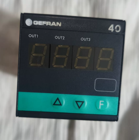
- 40ต: ชุด (40ไฟบอกสถานะ T48 48×48 มม / หน่วยเตือนภัย)
- 48: มิติข้อมูลแผง: 48×48 มม (1/16 จาก)
- 4: 4-จอแสดงผล LED หลัก
- 00: แหล่งจ่ายไฟ: 100…240 โวลต์ เอซี/ดีซี
- ร.ร: เอาท์พุต 1 & เอาท์พุต 2: รีเลย์คู่ (5ก / 250 วีและ)
- 0: 3เอาท์พุทลำดับ / อินพุตดิจิตอล / เอาท์พุทเครื่องส่งสัญญาณ: ไม่มี
- 0: อินเตอร์เฟซการสื่อสาร / 4เอาท์พุทที่: ไม่มี
- 0: จองไว้หน่อย.
- หลักสุดท้าย: 0 = ซอฟต์แวร์รุ่นเก่า / รุ่นพื้นฐาน; 1 = อัปเดตซอฟต์แวร์แล้ว / รุ่นที่ได้รับการรับรองการปฏิบัติตามข้อกำหนด (ซีอี, แอล, ฯลฯ)
- ความแตกต่างที่สำคัญ
ฮาร์ดแวร์ที่เหมือนกัน: เค้าโครงเทอร์มินัล, ขนาดการติดตั้ง, ช่วงแหล่งจ่ายไฟ, ข้อมูลจำเพาะหน้าสัมผัสรีเลย์และประเภทอินพุต (อินพุตสากล: สัญญาณ TC/RTD/เชิงเส้น) เหมือนกันทุกประการ. ไม่จำเป็นต้องดัดแปลงสายไฟ.
ฟังก์ชั่นที่เหมือนกัน: ทั้งสนับสนุน 3 จุดเตือนภัย, การเขียนโปรแกรมบนแผงควบคุม/ซอฟต์แวร์และการป้องกันด้วยรหัสผ่านพารามิเตอร์. ความแตกต่างเพียงอย่างเดียวคือเวอร์ชันเฟิร์มแวร์และการรับรองการปฏิบัติตามข้อกำหนด. รุ่นที่ลงท้ายด้วย. 1 เป็นเฟิร์มแวร์ที่อัปเดตแล้วซึ่งเข้ากันได้อย่างสมบูรณ์.
หมายเลขชิ้นส่วน: รุ่นที่ลงท้ายด้วย 0 = F000187; รุ่นที่ลงท้ายด้วย 1 = F000188.
- คำแนะนำในการเปลี่ยน & หมายเหตุ
- ✅ทดแทนโดยตรง: เข้ากันได้อย่างสมบูรณ์ในแง่ของการติดตั้ง, คำจำกัดความของสายไฟและขั้วต่อ. ไม่จำเป็นต้องเดินสายใหม่.
- ⚠️ การดำเนินการภาคบังคับ: กำหนดค่าพารามิเตอร์ใหม่ (ประเภทอินพุต, ช่วงการวัด, เกณฑ์การเตือน, ช่องว่างส่วนต่าง, ฯลฯ) หลังจากเปลี่ยนแล้ว. เฟิร์มแวร์ใหม่เข้ากันได้กับลอจิกพารามิเตอร์แบบเดิมอย่างสมบูรณ์.
- สถานการณ์พิเศษ: หากอุปกรณ์ดั้งเดิมต้องมีการตรวจสอบย้อนกลับของใบรับรองการปฏิบัติตามข้อกำหนดพิเศษ (เช่น. ตรงกับเอกสาร UL/CE), ตรวจสอบว่าจำเป็นต้องมีความสอดคล้องของโมเดลที่เข้มงวดในไซต์หรือไม่. สำหรับการใช้งานทั่วไป, จะไม่มีปัญหาเกิดขึ้น.
การอ้างอิงด่วนสำหรับการเปลี่ยน: อันตราย 40T-48-4-00-RR-0-0-0-0 / 40T-48-4-00-RR-0-0-1
- คำอธิบายรหัสรุ่นเต็ม (ต่างกันแค่เลขสุดท้ายเท่านั้น)
| ส่วนรหัส | เนื้อหา | คำอธิบาย | ความสอดคล้องระหว่างสองรุ่น |
| 1 | 40ต | ซีรี่ส์ผลิตภัณฑ์: 40T ตัวควบคุมสัญญาณเตือนแบบดิจิตอล | เหมือนกันหมด |
| 2 | 48 | ขนาดแผง: 48×48 มม (1/16 มาตรฐานของคุณ) | เหมือนกันหมด |
| 3 | 4 | แสดง: 4-หลอดดิจิตอล LED หลัก | เหมือนกันหมด |
| 4 | 0 | พาวเวอร์ซัพพลาย: แรงดันไฟฟ้ากว้าง 100~240 V AC/DC | เหมือนกันหมด |
| 5 | ร.ร | การกำหนดค่าเอาต์พุต: เอาต์พุตแจ้งเตือนรีเลย์อิสระ 2 ช่อง | เหมือนกันหมด |
| 6 | 0 | 3เอาท์พุทลำดับ / อินพุตดิจิตอล / เอาท์พุทเครื่องส่งสัญญาณ: ไม่มี | เหมือนกันหมด |
| 7 | 0 | พอร์ตการสื่อสาร / 4เอาท์พุทที่: ไม่มี | เหมือนกันหมด |
| 8 | 0 | ฮาร์ดแวร์สงวนบิต: ปิดใช้งานฟังก์ชันที่สงวนไว้ | เหมือนกันหมด |
| 9 | 0 / 1 | เฟิร์มแวร์ & เวอร์ชันการปฏิบัติตามข้อกำหนด: | ความแตกต่างเท่านั้น |
| 0 = เฟิร์มแวร์พื้นฐาน | |||
| 1 = อัพเดตเฟิร์มแวร์ (ได้รับการรับรอง CE/UL) |
> ข้อสรุปหลัก: 100% ความเข้ากันได้ในโครงสร้างฮาร์ดแวร์, ข้อกำหนดทางไฟฟ้า, เทอร์มินัลและพินการทำงาน. รองรับการทดแทนโดยตรง.
- ข้อมูลจำเพาะทางเทคนิคทั่วไป (เหมือนกันทั้งสองรุ่น)
| รายการ | ข้อมูลจำเพาะ |
| มิติการติดตั้ง | 48×แผง 48 มม, คัตเอาต์ DIN มาตรฐาน |
| กำลังปฏิบัติการ | 100 ~ 240 วี เอซี/ดีซี, การใช้พลังงาน < 3 เวอร์จิเนีย |
| อินพุตการวัด | ประเภทสากล: เทอร์โมคัปเปิ้ล (เค/เจ/เอส/ที), Pt100 RTD, สัญญาณอนาล็อกแรงดันไฟฟ้า/กระแสเชิงเส้น |
| แสดงความแม่นยำ | ±0.2% เอฟเอส, อัตราการสุ่มตัวอย่าง: 10 ครั้งต่อวินาที |
| เอาท์พุทรีเลย์ (ร.ร) | 2-ช่องผู้ติดต่อแบบพาสซีฟปกติเปิดอยู่, การจัดอันดับการติดต่อ: 5ก / 250 วีและ |
| อุณหภูมิในการทำงาน | 0 ~ +50 ℃ |
| การป้องกันทางเข้า | แผงด้านหน้า: IP65; ด้านเทอร์มินัล: IP20 |
| ความเป็นฉนวน | ทนต่อแรงดันไฟฟ้า 2000 V AC ระหว่างอินพุต, เอาท์พุทและแหล่งจ่ายไฟ |
- คำจำกัดความของเทอร์มินัลพิน (อเนกประสงค์สำหรับการเดินสายไฟในสถานที่, ไม่มีการเดินสายใหม่)
แผงขั้วต่อมาตรฐานที่ด้านหลังของอุปกรณ์, ทั้งหมด 8 ขั้ว. เค้าโครงและฟังก์ชันของเทอร์มินัลจะเหมือนกันทุกประการสำหรับทั้งสองรุ่น.
| เทอร์มินัลหมายเลข. | การทำงาน | คำแนะนำการเดินสายไฟ | หมายเหตุ |
| 1 | พาวเวอร์ แอล / + | เอซี ไลฟ์ / กระแสตรงบวก | กำลังไฟเข้า |
| 2 | พาวเวอร์ เอ็น / – | เอซีเป็นกลาง / กระแสตรงเป็นลบ | กำลังไฟเข้า |
| 3 | อินพุตการวัด + | สัญญาณเซ็นเซอร์เป็นบวก | เชื่อมต่อกับเทอร์โมคัปเปิล/RTD/เอาต์พุตแอนะล็อก |
| 4 | อินพุตการวัด – | สัญญาณเซ็นเซอร์เป็นลบ | จุดสิ้นสุดทั่วไปของลูปสัญญาณ |
| 5 | รีเลย์สัญญาณเตือน 1 ไม่มีการติดต่อ | 1เอาต์พุตสัญญาณเตือนเซนต์ | สอดคล้องกับลอจิกสัญญาณเตือนครั้งที่ 1 |
| 6 | รีเลย์สัญญาณเตือน 1 ทั่วไป | ขั้วต่อทั่วไปของรีเลย์ 1 | การติดต่อแบบพาสซีฟ, ไม่ใช่ขั้ว |
| 7 | รีเลย์สัญญาณเตือน 2 ไม่มีการติดต่อ | 2เอาต์พุตแจ้งเตือนครั้งที่ 2 | สอดคล้องกับลอจิกการเตือนครั้งที่ 2 |
| 8 | รีเลย์สัญญาณเตือน 2 ทั่วไป | ขั้วต่อทั่วไปของรีเลย์ 2 | การติดต่อแบบพาสซีฟ, ไม่ใช่ขั้ว |
เสริม: รุ่นนี้ไม่มีเอาต์พุตตัวส่งสัญญาณหรือพอร์ตการสื่อสาร, และเทอร์มินัลทั้งหมดถูกใช้อย่างเต็มที่. ลวดอย่างเคร่งครัดตามตารางข้างต้น.
- ปุ่มแผง & การกำหนดค่าพารามิเตอร์ทีละขั้นตอน (บังคับหลังจากการเปลี่ยน)
คำอธิบายที่สำคัญ
`SET`: เข้าเมนู / ยืนยันพารามิเตอร์ / สลับระดับเมนู
`▲/▼`: ปรับค่า / สลับตัวเลือก
`◀`: เลื่อนหลัก / กลับไปยังเมนูก่อนหน้า
ทำตามขั้นตอนการกำหนดค่าให้เสร็จสมบูรณ์ (ทั่วไปสำหรับการสมัครภาคสนาม)
ขั้นตอน 1: เข้าสู่โหมดการเขียนโปรแกรม
กด `SET` ค้างไว้เพื่อ 3 วินาทีเพื่อเข้าสู่อินเทอร์เฟซการตั้งค่าพารามิเตอร์. สำหรับบางยูนิต, ป้อนรหัสผ่านเริ่มต้นจากโรงงาน 0000 และกด `SET` เพื่อยืนยัน.
ขั้นตอน 2: ตั้งค่าประเภทสัญญาณอินพุต (การตั้งค่าหลัก)
- ค้นหาพารามิเตอร์ `In.Ty` (ประเภทอินพุต)
- ใช้ `▲/▼` เพื่อเลือกประเภทเซ็นเซอร์:
`เค: เทอร์โมคัปเปิลชนิด K
`ปต: Pt100 RTD
`0-10`: 0-10V สัญญาณอนาล็อก
`4-20`: 4-20mA สัญญาณอนาล็อก
- กด `SET` เพื่อบันทึกและดำเนินการไปยังรายการถัดไป.
ขั้นตอน 3: ตั้งค่าช่วงการวัด
- 'หล่อ': ตั้งค่าขีดจำกัดช่วงล่าง
- 'สวัสดี': ตั้งค่าขีดจำกัดช่วงบน
- ปรับตามช่วงกระบวนการจริง, จากนั้นกด `SET` เพื่อยืนยัน.
ขั้นตอน 4: กำหนดค่ารีเลย์สัญญาณเตือนแบบคู่ (สอดคล้องกับเอาต์พุต RR)
- `อัล1`: 1ค่าสัญญาณเตือนเซนต์ (สำหรับรีเลย์บนเทอร์มินัล 5/6)
- `dF1`: ช่องว่างส่วนต่างของสัญญาณเตือนครั้งที่ 1 (เพื่อป้องกันการสลับรีเลย์บ่อยครั้ง, ค่าที่แนะนำ: 0.5~2.0)
- `อัล2`: 2ค่าการเตือนครั้งที่ 1 (สำหรับรีเลย์บนเทอร์มินัล 7/8)
- `dF2`: ช่องว่างส่วนต่างของสัญญาณเตือนครั้งที่ 2
- เลือกโหมดการเตือน: สัญญาณเตือนขีดจำกัดสูง / สัญญาณเตือนขีดจำกัดต่ำตามต้องการ.
ขั้นตอน 5: บันทึกพารามิเตอร์ & ออก
หลังจากตั้งค่าทั้งหมดเสร็จแล้ว, กด `◀` ซ้ำๆ เพื่อกลับไปยังอินเทอร์เฟซหลัก. พารามิเตอร์จะถูกบันทึกโดยอัตโนมัติ.
เพื่อล็อคพารามิเตอร์จากการดัดแปลงโดยไม่ตั้งใจ: ค้นหา `P.cod` และตั้งรหัสผ่านที่กำหนดเอง.
- รายการตรวจสอบนอกสถานที่หลังการเปลี่ยน (ตรวจสอบทีละรายการเพื่อหลีกเลี่ยงข้อผิดพลาด)
การตรวจสอบก่อนเปิดเครื่อง
- การติดตั้งทางกล: ยึดเครื่องมือไว้บนแผงโดยไม่หลวม; ขนาดคัตเอาท์ 48×48 มม.
- การตรวจสอบสายไฟ: ตรวจสอบพลังงาน, วงจรเซ็นเซอร์และรีเลย์ต่อตารางเทอร์มินัล; ตรวจสอบให้แน่ใจว่าไม่มีการเชื่อมต่อที่หลวม, การเดินสายไฟผิดหรือไฟฟ้าลัดวงจร.
- การยืนยันพลังงาน: แหล่งจ่ายไฟในสถานที่คือ 100~240 V AC/DC ภายในช่วงพิกัด.
การตรวจสอบหลังเปิดเครื่อง
- การทดสอบการเปิดเครื่อง: 4-ตัวเลข LED สว่างขึ้นตามปกติ, ไม่มีหน้าจอสีดำหรือกะพริบ.
- การตรวจสอบสัญญาณ: เปรียบเทียบการอ่านแบบเรียลไทม์กับค่าเซ็นเซอร์จริง; ตรวจสอบให้แน่ใจว่าส่วนเบี่ยงเบนอยู่ภายในช่วงที่อนุญาต.
- การทดสอบสัญญาณเตือน: จำลองเงื่อนไขเกินขีดจำกัดด้วยตนเอง; ยืนยันว่ารีเลย์สองตัวทำงาน/ลดพลังงานตามปกติ และโหลดภายนอกทำงานอย่างถูกต้อง.
- ตรวจสอบพารามิเตอร์อีกครั้ง: รักษาระยะ, ค่าสัญญาณเตือนและช่องว่างส่วนต่างที่สอดคล้องกับการตั้งค่าดั้งเดิม.
การตรวจสอบการปฏิบัติตามข้อกำหนด (ดำเนินการตามความจำเป็น)
พื้นที่อุตสาหกรรมทั่วไป / ไม่จำเป็นต้องมีการตรวจสอบย้อนกลับของใบรับรอง: ไม่จำเป็นต้องดำเนินการเพิ่มเติม.
อุปกรณ์ส่งออก / รูปแบบที่เข้มงวด & ต้องมีความสอดคล้องของใบรับรอง: รุ่นใหม่ลงท้ายด้วย 1 เป็นรุ่นที่ได้รับการรับรองพร้อมเอกสาร CE/UL ที่สมบูรณ์สำหรับการยื่น.
- ข้อผิดพลาดทั่วไป & การแก้ไขปัญหาหลังการเปลี่ยน
| ปรากฏการณ์ความผิดปกติ | สาเหตุที่เป็นไปได้ | โซลูชั่น |
| ไม่มีการแสดงผลหลังจากเปิดเครื่อง | 1. สายไฟย้อนกลับ/หลวม | ขันขั้วต่อให้แน่น, วัดแรงดันไฟฟ้าขาเข้าและเรียกคืนแหล่งจ่ายไฟที่กำหนด |
| 2. จ่ายแรงดันไฟฟ้าอยู่นอกช่วง | ||
| มีความผันผวน / การอ่านที่ไม่ถูกต้อง | 1. การเชื่อมต่อเซ็นเซอร์ไม่ดี | เชื่อมต่อสายเซ็นเซอร์อีกครั้งและตรวจสอบพารามิเตอร์ In.Ty |
| 2. เลือกประเภทอินพุตไม่ถูกต้อง | ||
| การอ่านปกติแต่ไม่มีการดำเนินการใดๆ | 1. ค่าสัญญาณเตือนไม่ถูกต้อง | ตรวจสอบเกณฑ์ AL1/AL2 อีกครั้ง และสลับโหมดสัญญาณเตือน |
| 2. เลือกโหมดการเตือนไม่ถูกต้อง | ||
| รีเลย์สวิตช์บ่อย | ช่องว่างส่วนต่างเล็กเกินไป | เพิ่มค่า dF1/dF2 |
| พารามิเตอร์รีเซ็ตโดยอัตโนมัติ | ไม่สามารถออกจากเมนูได้อย่างสมบูรณ์ / ปุ่มแผงค้าง | ออกจากอินเทอร์เฟซการตั้งค่าอย่างสมบูรณ์และทำความสะอาดสิ่งแปลกปลอมบนคีย์ |
- หมายเหตุเพิ่มเติม
- ความเข้ากันได้ของเฟิร์มแวร์: เฟิร์มแวร์ที่อัพเดตแล้ว (ลงท้ายด้วย 1) สามารถใช้งานร่วมกับลอจิกพารามิเตอร์แบบเดิมได้อย่างสมบูรณ์แบบย้อนหลัง, โดยไม่มีการลดฟังก์ชันหรือโปรโตคอลไม่ตรงกัน.
- การจัดซื้ออะไหล่: ทั้งสองรุ่นสามารถใช้แทนกันได้เพื่อสั่งซื้อใหม่. เวอร์ชันอัปเดตลงท้ายด้วย 1 แนะนำให้ใช้เพื่อให้ครอบคลุมการรับรองที่กว้างขึ้น.
- การดำเนินงานระยะยาว: ทั้งสองรุ่นมีอายุการใช้งานและความสามารถในการรับน้ำหนักเท่ากัน, และไม่จำเป็นต้องมีมาตรฐานการบำรุงรักษาที่แตกต่างกัน.

