 คอนแทคเตอร์,เบรกเกอร์,อินเวอร์เตอร์พลังงานแสงอาทิตย์,มิเตอร์ไฟฟ้า,แบตเตอรี่พลังงานแสงอาทิตย์

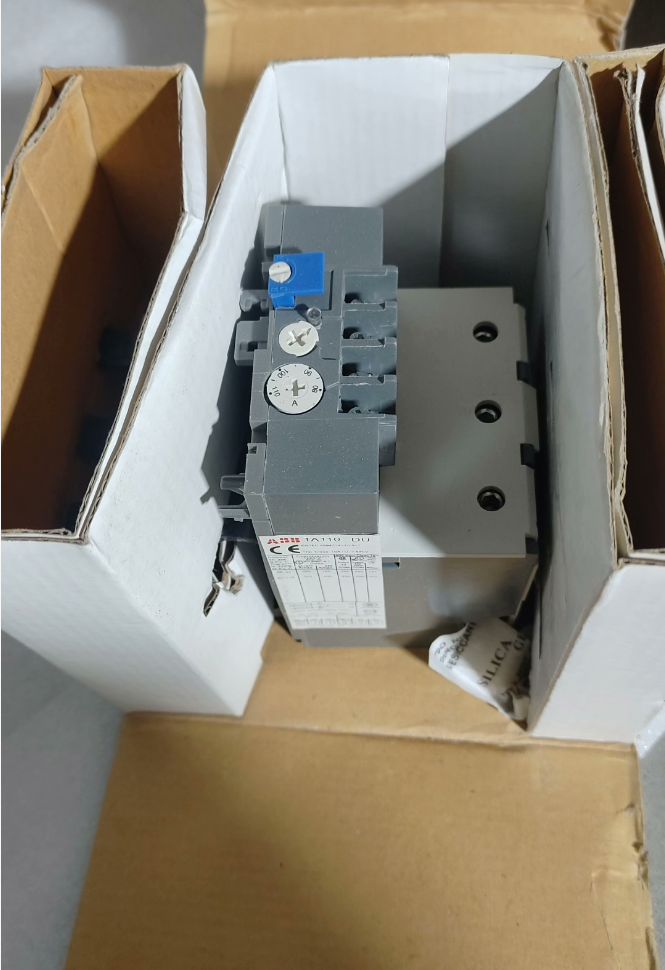

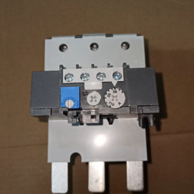
TA110DU110 เป็น 3 ขั้วแบบคลาสสิก รีเลย์โอเวอร์โหลดความร้อน จาก เอบีบี ทีเอ ซีรีส์, ให้การป้องกันแบบรวมสำหรับมอเตอร์แบบอะซิงโครนัสสามเฟสที่มีช่วงกระแสไฟพิกัด 80~110A. การใช้หลักการสะดุดเวลาผกผันของแถบโลหะคู่, รีเลย์นี้มาพร้อมกับการป้องกันการสูญเสียเฟสและการชดเชยอุณหภูมิแวดล้อมอัตโนมัติเป็นมาตรฐาน, ด้วยชั้นการเดินทางของคลาส 10A. สามารถเสียบเข้ากับคอนแทคเตอร์ซีรีส์ ABB A/AE/AF95~110 ได้โดยตรง หรือติดตั้งแยกกันบนราง DIN. มีโหมดรีเซ็ตแบบแมนนวล/อัตโนมัติแบบสลับได้และโหมดเปิดตามปกติ (เลขที่) บวกหนึ่งปิดตามปกติ (เอ็นซี) หน้าสัมผัสสัญญาณเสริม, ทำหน้าที่เป็นส่วนประกอบป้องกันมาตรฐานสำหรับวงจรควบคุมมอเตอร์อุตสาหกรรม. ใช้กันอย่างแพร่หลายกับโหลดกำลังเช่นพัดลม, ปั๊มน้ำ, คอมเพรสเซอร์และสายพานลำเลียง, ช่วยป้องกันอุบัติเหตุมอเตอร์ที่เกิดจากการโอเวอร์โหลดได้อย่างมีประสิทธิภาพ, โรเตอร์ที่ถูกล็อคและการสูญเสียเฟส.
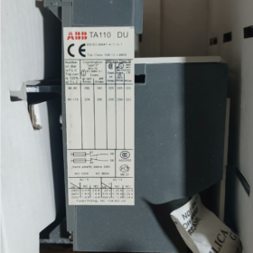
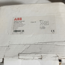
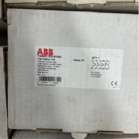
รุ่นเต็ม: `TA110DU110`
- เผชิญหน้า: รหัสชุดทั่วไปสำหรับรีเลย์โอเวอร์โหลดความร้อน ABB, เป็นตัวแทนของตระกูลรีเลย์ป้องกันความร้อนด้วยไฟฟ้า
- 110: เฟรมเรตติ้งปัจจุบัน, ระบุกระแสเฟรมพิกัดสูงสุดที่ 110A สำหรับผลิตภัณฑ์นี้
- ของ: รหัสประเภทฟังก์ชั่น, ย่อมาจากข้อกำหนดมาตรฐานที่มีการป้องกันแบบ 3 ขั้ว, การตรวจจับการสูญเสียเฟส, การชดเชยอุณหภูมิโดยรอบและการติดตั้งโดยตรงบนคอนแทคเตอร์
- 110: ขีดจำกัดบนของการตั้งค่าปัจจุบัน, สอดคล้องกับช่วงกระแสที่ปรับได้ของ 80A ~ 110A
ข้อมูลจำเพาะทางเทคนิคหลัก
| หมวดหมู่พารามิเตอร์ | รายการพารามิเตอร์ | ข้อมูลจำเพาะโดยละเอียด |
| ลักษณะวงจรหลัก | พิกัดแรงดันไฟฟ้าฉนวน Ui | 690วีและ / 440ในดีซี |
| แรงดันไฟฟ้าในการทำงานพิกัด UL/CSA | 600วีและ | |
| ช่วงปัจจุบันที่ปรับได้ | ปรับได้อย่างต่อเนื่องตั้งแต่ 80A ถึง 110A | |
| คลาสการเดินทาง | คลาส 10A (ระดับการป้องกันมอเตอร์มาตรฐาน) | |
| จำนวนเสา | 3 เสา, การป้องกันแบบ 3 ขั้วเต็มรูปแบบ | |
| การป้องกันการสูญเสียเฟส | มาตรฐานในตัว; เร่งการสะดุดภายใต้ความไม่สมดุลสามเฟส | |
| การชดเชยอุณหภูมิ | รองรับ; ความแม่นยำในการป้องกันยังคงไม่ได้รับผลกระทบภายในอุณหภูมิแวดล้อม -25°C ~ +55°C | |
| ติดต่อเสริม | การกำหนดค่าการติดต่อ | 1 เลขที่ + 1 เอ็นซี, แยกด้วยไฟฟ้า |
| กระแสความร้อนแบบธรรมดา Ith | 5ก | |
| ความจุการติดต่อที่ได้รับการจัดอันดับ | AC250V 3A; DC24V 5A | |
| เครื่องกล & การติดตั้ง | วิธีการติดตั้ง | ติดตั้งโดยตรงบนคอนแทคเตอร์ / การติดตั้งราง DIN อิสระ |
| คอนแทคเตอร์ที่เข้ากันได้ | ซีรีส์ A95, A110, AE95, AE110, AF95, AF110 | |
| วิธีการเดินสายไฟ | ขั้วต่อแบบสกรูยึด | |
| น้ำหนักโดยรวม | ประมาณ. 0.76กก | |
| รีเซ็ตโหมด | รีเซ็ตด้วยตนเอง / อัตโนมัติแบบสลับได้; รองรับการขยายการรีเซ็ตระยะไกล | |
| สิ่งแวดล้อม & การรับรอง | อุณหภูมิแวดล้อมในการทำงาน | -25℃ ~ +55 ℃ |
| อุณหภูมิในการจัดเก็บ | -40℃ ~ +70 ℃ | |
| ระดับการป้องกันน้ำเข้า | IP20 | |
| การรับรองการปฏิบัติตามข้อกำหนด | ซีอี, แอล, ซีเอสเอ, ซีซีซี, GL (การรับรองจาก Germanischer Lloyd Marine) | |
| เป็นไปตามมาตรฐาน | ไออีซี 60947-4-1, ใน 60947-4-1 |
การอ้างอิงโยงของโมเดลภายในซีรีส์เดียวกัน
- ข้อมูลจำเพาะทั้งหมดของเฟรม TA110DU
| รุ่นเต็ม | ช่วงปัจจุบันที่ปรับได้ | กำลังมอเตอร์ที่เข้ากันได้ (380วี) | คอนแทคเตอร์ที่ตรงกัน |
| TA110DU-65 | 50 ~65เอ | 30กิโลวัตต์ | A95/AE95/AF95 |
| TA110DU-80 | 60 ~ 80A | 37กิโลวัตต์ | A95/AE95/AF95 |
| TA110DU-90 | 66 ~ 90เอ | 45กิโลวัตต์ | A110/AE110/AF110 |
| TA110DU-110 | 80 ~ 110A | 55กิโลวัตต์ | A110/AE110/AF110 |
- การเปรียบเทียบซีรี่ส์เฟรมที่อยู่ติดกัน
| ซีรีส์โมเดล | เฟรมจัดอันดับปัจจุบัน | กระแสไฟที่ปรับได้สูงสุด | สถานการณ์ที่เกี่ยวข้อง |
| TA110DU | 110ก | 110ก | ปานกลาง & มอเตอร์ไฟฟ้าขนาดเล็ก (30~55กิโลวัตต์) |
| TA200DU | 200ก | 200ก | ปานกลาง & มอเตอร์กำลังขนาดใหญ่ (75~110กิโลวัตต์) |
| TA450DU | 450ก | 450ก | มอเตอร์สำหรับงานหนักกำลังสูง (132~250กิโลวัตต์) |
สถานการณ์การใช้งานทั่วไป
- วงจรป้องกันสตาร์ทมอเตอร์มาตรฐาน: เมื่อใช้ร่วมกับคอนแทคเตอร์ซีรีส์ ABB A/AF เพื่อสร้างสตาร์ทเตอร์แบบแม่เหล็กไฟฟ้า, เชื่อมต่อแบบอนุกรมกับวงจรหลักของมอเตอร์สามเฟสเพื่อป้องกันมอเตอร์โอเวอร์โหลด, โรเตอร์ที่ถูกล็อคและการสูญเสียเฟส. เป็นโซลูชั่นการป้องกันมาตรฐานสำหรับอุปกรณ์ไฟฟ้าทั่วไปรวมถึงพัดลม, ปั๊มน้ำ, เครื่องอัดอากาศและแกนหมุนของเครื่องมือกล.
- ศูนย์ควบคุมมอเตอร์ MCC: ทำหน้าที่เป็นหน่วยป้องกันมาตรฐานสำหรับวงจรป้อนมอเตอร์ในตู้ลิ้นชักและตู้แบบตายตัว, บูรณาการกับคอนแทคเตอร์เพื่อให้เกิดการควบคุมและการป้องกันการสตาร์ท-หยุดมอเตอร์ในตัว.
- สายพานลำเลียง & ระบบคัดแยกลอจิสติกส์: จับคู่กับมอเตอร์ลูกกลิ้งและมอเตอร์ขับเคลื่อนการเรียงลำดับ, ปรับให้เข้ากับสภาพการทำงานของการสตาร์ท-หยุดบ่อยครั้งและความผันผวนของโหลดของสายการผลิต, และป้องกันการเสื่อมสภาพของมอเตอร์และความเหนื่อยหน่ายที่เกิดจากการโอเวอร์โหลดในระยะยาว.
- เครื่องปรับอากาศส่วนกลาง & หน่วยทำความเย็น: ปกป้องอุปกรณ์จ่ายไฟทำความเย็น เช่น คอมเพรสเซอร์ และพัดลมคูลลิ่งทาวเวอร์, เหมาะกับลักษณะของอุตสาหกรรมเครื่องทำความเย็นที่มีความผันผวนของโหลดอย่างรุนแรงและการทำงานที่มีโหลดสูงตามฤดูกาล.
- การสนับสนุนอุปกรณ์ OEM ที่สมบูรณ์: เข้ากันได้อย่างกว้างขวางกับเครื่องจักรอุตสาหกรรมรวมถึงเครื่องจักรบรรจุภัณฑ์, ยาง & เครื่องจักรพลาสติกและอุปกรณ์เสริมทางโลหะวิทยา. เป็นส่วนประกอบป้องกันมอเตอร์ที่ได้มาตรฐาน, เป็นไปตามข้อกำหนดข้อกำหนดด้านความปลอดภัยทางไฟฟ้าสำหรับการส่งมอบอุปกรณ์ในโรงงาน.
เมทริกซ์การแก้ไขปัญหาทั่วไป
| ปรากฏการณ์ความผิดปกติ | การวิเคราะห์สาเหตุที่แท้จริง | โซลูชั่นทีละขั้นตอน |
| รีเลย์ทริปผิดพลาดระหว่างการทำงานของมอเตอร์ปกติ | 1. ค่าการตั้งค่าปัจจุบันต่ำ, ต่ำกว่าพิกัดกระแสของมอเตอร์ | 1. ตรวจสอบกระแสไฟที่กำหนดของมอเตอร์และปรับปุ่มปรับตั้งให้เป็นค่าพิกัดที่สอดคล้องกัน |
| 2. อุณหภูมิแวดล้อมสูงเกินไปเกินช่วงการชดเชย | 2. ปรับปรุงการกระจายความร้อนของตู้และหลีกเลี่ยงแสงแดดโดยตรงหรือรังสีจากแหล่งความร้อน | |
| 3. การเบี่ยงเบนกระแสอย่างรุนแรงที่เกิดจากความไม่สมดุลของแรงดันไฟฟ้าสามเฟส | 3. วัดกระแสสามเฟสเพื่อแก้ไขปัญหาความเสี่ยงที่ซ่อนอยู่ของความไม่สมดุลของแรงดันไฟฟ้าหรือการสูญเสียเฟส | |
| 4. เวลาสตาร์ทมอเตอร์นานเกินขีดจำกัดของคลาส 10 ชั้นการเดินทาง | 4. แทนที่ด้วยรีเลย์โอเวอร์โหลดความร้อนของคลาส 20 หรือชั้นเรียน 30 สำหรับแอพพลิเคชั่นสตาร์ทอัพที่มีภาระงานหนัก | |
| รีเลย์ล้มเหลวในการเดินทางภายใต้มอเตอร์โอเวอร์โหลดหรือโรเตอร์ล็อค | 1. ค่าการตั้งค่ากระแสสูงเกินไป, สูงกว่ากระแสไฟที่กำหนดของมอเตอร์มาก | 1. ปรับเทียบค่าการตั้งค่าใหม่เพื่อให้ตรงกับกระแสไฟที่กำหนดของมอเตอร์อย่างเคร่งครัด |
| 2. ขั้วต่อสายไฟวงจรหลักหลวมทำให้เกิดความต้านทานต่อการสัมผัสมากเกินไป | 2. ขันขั้วต่อวงจรหลักให้แน่นและแก้ไขปัญหาความร้อนสูงเกินไป & ปัญหาการเกิดออกซิเดชัน | |
| 3. กลไกกลไกรีเลย์ติดอยู่และชุดประกอบสะดุดล้ม | 3. ตัดไฟและทดสอบความยืดหยุ่นของกลไกการสะดุดด้วยตนเอง; เปลี่ยนโมดูลหากเกิดการติดขัด | |
| การป้องกันไม่เปิดใช้งานเมื่อเกิดข้อผิดพลาดในการสูญเสียเฟส | 1. สายไฟขาเข้าสามเฟสผิดพร้อมการเชื่อมต่อที่ไม่สมบูรณ์กับวงจรหลักของรีเลย์ | 1. ตรวจสอบการเดินสายไฟสามเฟส L1/L2/L3 เพื่อให้แน่ใจว่าทุกเฟสเชื่อมต่อได้อย่างน่าเชื่อถือ |
| 2. การเสื่อมสภาพและความล้มเหลวของส่วนประกอบไบเมทัลลิกภายใน | 2. จำลองการสูญเสียเฟสโดยไม่ได้ตั้งใจเพื่อทดสอบฟังก์ชันการป้องกัน; เปลี่ยนรีเลย์หากฟังก์ชันล้มเหลว | |
| สัญญาณหน้าสัมผัสเสริมผิดปกติหรือไม่มีเลย | 1. โหลดหน้าสัมผัสเสริมเกินความจุที่กำหนด, ส่งผลให้เกิดความเหนื่อยหน่ายในการติดต่อ | 1. ยืนยันว่ากระแสโหลดไม่เกินระดับการสัมผัส; เพิ่มรีเลย์กลางสำหรับการขยายกระแสหากจำเป็น |
| 2. ไม่มีการรีเซ็ตหลังจากสะดุด, ผู้ติดต่อยังคงอยู่ในสถานะผิด | 2. รีเซ็ตรีเลย์ด้วยตนเองหรือโดยอัตโนมัติหลังจากแก้ไขปัญหาสาเหตุของข้อบกพร่องที่รูท | |
| 3. การสัมผัสไม่ดีเนื่องจากการสัมผัสออกซิเดชัน | 3. วัดความต้านทานการเปิด-ปิดหน้าสัมผัส; เปลี่ยนโมดูลหากมีการสัมผัสที่ไม่ดี |
- นิยามเทอร์มินัล & คำอธิบายฟังก์ชั่น
TA110DU110 ใช้กฎการกำหนดหมายเลขเทอร์มินอลมาตรฐานอุตสาหกรรม, แบ่งออกเป็นสองส่วน: วงจรไฟฟ้าหลักและวงจรควบคุมเสริม. ขั้วต่อทั้งหมดเป็นแบบสกรูยึดด้านหน้า โดยสามารถเดินสายไฟทั้งหมดได้จากด้านหน้า.
- ขั้วต่อวงจรหลัก (วงจรไฟฟ้าสามเฟส)
| เทอร์มินัลมาร์ค | ประเภทเทอร์มินัล | คำแนะนำในการเดินสายไฟ |
| 1L1, 3L2, 5L3 | อาคารผู้โดยสารขาเข้า | อินพุตด้านบน, เชื่อมต่อกับขั้วเอาท์พุทของหน้าสัมผัสหลักของคอนแทคเตอร์, สอดคล้องกับไฟสามเฟส L1/L2/L3 |
| 2T1, 4ที2, 6T3 | เทอร์มินัลขาออก | เอาต์พุตด้านล่าง, เชื่อมต่อโดยตรงกับขดลวดสเตเตอร์ของมอเตอร์แบบอะซิงโครนัสสามเฟส |
หมายเหตุ: วงจรหลักสามเฟสไม่มีข้อกำหนดด้านขั้วไฟฟ้า, แต่แต่ละเฟสจะต้องเชื่อมต่อกันแบบตัวต่อตัวโดยไม่มีการเชื่อมต่อผิดพลาดแบบข้ามเฟส. เมื่อติดตั้งบนคอนแทคเตอร์โดยตรง, วงจรหลักจะดำเนินการโดยอัตโนมัติผ่านแท่งทองแดงแบบเสียบปลั๊ก โดยไม่ต้องเดินสายไฟเพิ่มเติม.
- ขั้วต่อวงจรเสริม (ควบคุม & วงจรสัญญาณ)
| เทอร์มินัลมาร์ค | ประเภทการติดต่อ | คำอธิบายฟังก์ชั่น | วัตถุประสงค์ในการเดินสายไฟทั่วไป |
| 95 – 96 | ปกติปิด (เอ็นซี) | เป็นสื่อกระแสไฟฟ้าภายใต้สภาวะการทำงานปกติ; เปิดขึ้นเมื่อมีการสะดุดที่เกิดจากการโอเวอร์โหลด/การสูญเสียเฟส | เชื่อมต่อแบบอนุกรมกับวงจรควบคุมคอยล์คอนแทคเตอร์เพื่อตัดการจ่ายไฟให้กับคอนแทคเตอร์และหยุดมอเตอร์เมื่อเกิดข้อผิดพลาด |
| 97 – 98 | เปิดตามปกติ (เลขที่) | ตัดการเชื่อมต่อภายใต้สภาวะการทำงานปกติ; ปิดเมื่อสะดุดที่เกิดจากการโอเวอร์โหลด/การสูญเสียเฟส | เชื่อมต่อกับวงจรสัญญาณเตือนด้วยเสียงหรือจุดอินพุตดิจิตอล PLC สำหรับการอัปโหลดสัญญาณข้อผิดพลาดและการแจ้งเตือน |
หน้าสัมผัสเสริมถูกแยกทางไฟฟ้าโดยไม่มีการเชื่อมต่อทางไฟฟ้ากับวงจรหลักและมีกระแสความร้อนทั่วไปที่ 5A. แนะนำให้ใช้รีเลย์ระดับกลางสำหรับการเชื่อมต่อแบบอนุกรมเพื่อขยายขีดความสามารถและป้องกันการเหนื่อยหน่ายของหน้าสัมผัสเมื่อควบคุมโหลดกำลังสูง.
- แผนการเดินสายไฟทั่วไป
- การเดินสายไฟติดตั้งโดยตรงบนคอนแทค (ใช้กันมากที่สุด)
นี่เป็นวิธีการสมัครมาตรฐานสำหรับ TA110DU110. เสียบเข้ากับด้านบนของคอนแทคเตอร์ ABB A95/A110/AF95/AF110 โดยตรง. วงจรหลักจะเชื่อมต่อโดยอัตโนมัติผ่านขั้วต่อปลั๊กอินภายใน, มีเพียงวงจรควบคุมที่ต้องเดินสายไฟภายนอกเท่านั้น:
- ไฟสามเฟสส่งผ่านเบรกเกอร์และเชื่อมต่อกับขั้วต่อขาเข้าหลักของคอนแทคเตอร์ L1/L2/L3
- หลังจากติดตั้งรีเลย์โอเวอร์โหลดความร้อนบนคอนแทคโดยตรงแล้ว, วงจรหลักจะดำเนินการโดยอัตโนมัติโดยไม่ต้องเดินสายไฟเพิ่มเติม
- ปลายด้านหนึ่งของแหล่งจ่ายไฟควบคุมจะผ่านปุ่มหยุดและสตาร์ท และเชื่อมต่อกับขั้วต่อคอยล์คอนแทคเตอร์ A1
- ที่ 95-96 หน้าสัมผัส NC ของรีเลย์ความร้อนเชื่อมต่อแบบอนุกรมกับสายไฟปัจจุบันของวงจรคอยล์คอนแทคเตอร์เพื่อให้ทราบถึงการปิดมอเตอร์อัตโนมัติภายใต้โอเวอร์โหลด
- ที่ 97-98 ไม่มีหน้าสัมผัสของรีเลย์ความร้อนขนานกับไฟแสดงสถานะความผิดปกติหรือเชื่อมต่อกับจุด PLC DI เพื่อแจ้งเตือนข้อผิดพลาด
- สายไฟติดตั้งราง DIN อิสระ
การติดตั้งรางอิสระถูกนำมาใช้สำหรับการติดตั้งแยกกันหรือจับคู่กับคอนแทคเตอร์ของยี่ห้ออื่น:
- ขั้วต่อเอาต์พุตคอนแทคเตอร์ L1/L2/L3 เชื่อมต่อกับเทอร์มินัลขาเข้าของรีเลย์ความร้อน 1L1/3L2/5L3 ผ่านสายไฟ
- Thermal relay outgoing terminals 2T1/4T2/6T3 connect to motor three-phase terminals
- The control circuit follows the same wiring logic as the direct mounting scheme, กับ 95-96 NC contact wired in series into the contactor coil circuit
ข้อควรระวังในการเดินสายไฟ:
The cross-sectional area of main circuit cables shall match the 110A rated current; 25mm² copper cables are recommended
1~1.5mm² control cables are suggested for auxiliary control circuits
Reliable earthing is mandatory to guarantee personal and equipment safety
III. Parameter Comparison Table of Cross-Brand Equivalent Models
Below is a parameter comparison of mainstream thermal overload relays of the same current range from Siemens and Schneider Electric, for reference during alternative selection:
| รายการเปรียบเทียบ | เอบีบี | ชไนเดอร์ อิเล็คทริค | ซีเมนส์ |
| รุ่นเต็ม | TA110DU110 | LRD3365C | 3RU5146-4MB1 |
| ช่วงปัจจุบันที่ปรับได้ | 80 ~ 110A | 80 ~ 104A | 80 ~ 100A |
| เฟรมจัดอันดับปัจจุบัน | 110ก | 115ก | 140ก |
| คลาสการเดินทาง | คลาส 10A | ระดับ 10 | ระดับ 10 |
| จำนวนเสา | 3 เสา | 3 เสา | 3 เสา |
| การกำหนดค่าการติดต่อเสริม | 1เลขที่ + 1เอ็นซี (แยกด้วยไฟฟ้า) | 1เลขที่ + 1เอ็นซี (แยกด้วยไฟฟ้า) | 1เลขที่ + 1เอ็นซี (แยกด้วยไฟฟ้า) |
| การป้องกันการสูญเสียเฟส | มาตรฐานในตัว | มาตรฐานในตัว | มาตรฐานในตัว |
| การชดเชยอุณหภูมิโดยรอบ | รองรับ (-25℃~+55℃) | รองรับ (-20℃~+60℃) | รองรับ (-20℃~+60℃) |
| รีเซ็ตโหมด | Switchable manual/automatic | Switchable manual/automatic | Switchable manual/automatic |
| Compatible Contactor Series | A95~A110, AF95~AF110 | LC1D95~LC1D115 | 3RT5045~3RT5046 |
| วิธีการติดตั้ง | ติดตั้งโดยตรงบนคอนแทคเตอร์ / รางปีกนก | ติดตั้งโดยตรงบนคอนแทคเตอร์ / รางปีกนก | ติดตั้งโดยตรงบนคอนแทคเตอร์ / รางปีกนก |
| การรับรองการปฏิบัติตามข้อกำหนด | ซีอี, แอล, ซีซีซี, GL | ซีอี, แอล, ซีซีซี | ซีอี, แอล, ซีซีซี |


 Impulse Heat-Sealing Temperature Controller")


")


NH42-63-318x560.png "สวิตช์ถ่ายโอนอัตโนมัติชนิด CHINT PC (เอทีเอส)NH42-63/4SZ")


