 คอนแทคเตอร์,เบรกเกอร์,อินเวอร์เตอร์พลังงานแสงอาทิตย์,มิเตอร์ไฟฟ้า,แบตเตอรี่พลังงานแสงอาทิตย์


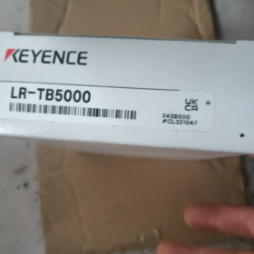
The KEYENCE LR-TB5000 is an amplifier-built-in TOF laser distance เซ็นเซอร์ of KEYENCE LR-T series. เป็นรุ่นแบบกระจายแสงสะท้อนสำหรับการตรวจจับระยะไกล, พร้อมสายตรงมาตรฐานและจัดอยู่ในประเภท Laser Class 2. Adopting Time-of-Flight measurement principle, it delivers stable distance measurement and object presence detection within 60mm to 5000mm. Its performance is barely affected by the color, material or surface angle of targets. Featuring IP65/IP67 high ingress protection, it is widely applied in complex working conditions such as industrial automation production lines, โลจิสติกส์ & warehousing and construction machinery. It is a mainstream choice for long-distance and high-reliability detection on industrial sites.
- รายละเอียดรหัสรุ่น
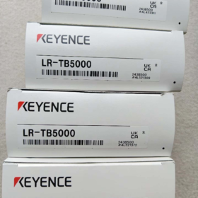
แบบอย่าง: LR-TB5000
| ส่วนรหัส | คำอธิบาย |
| LR-T | ซีรี่ส์ผลิตภัณฑ์: General series of amplifier-built-in TOF laser sensors |
| บี | ประเภทการตรวจจับ: Diffuse-reflective type (no reflector required, directly detects target surfaces) |
| 5000 | Maximum standard detection distance: 5000มม (5ม), tested with white matte paper as reference |
| ไม่มีคำต่อท้าย | Cable outlet: Straight cable type; คลาสเลเซอร์: ระดับ 2 (Compliant with IEC60825-1 and FDA(CDRH) มาตรฐาน) |
Supplementary rules for suffixes of the same series: Suffix `C` stands for M12 connector type; Suffix `CL` stands for M12 connector with low-power Laser Class 1.
- ข้อมูลจำเพาะทางเทคนิคหลัก
2.1 ประสิทธิภาพการตรวจจับ
| พารามิเตอร์ | ข้อมูลจำเพาะ | หมายเหตุ |
| Standard Detection Range | 60 ~ 5000 มม | Display range: 50~5200mm; Tested on white matte paper |
| แหล่งกำเนิดแสง | Red semiconductor laser, wavelength: 660นาโนเมตร | คลาสเลเซอร์ 2, สูงสุด. output power ≤1mW |
| Spot Diameter | Variable, ≤φ40mm | Spot size varies linearly with detection distance |
| เวลาตอบสนอง | 5 selectable levels: 1นางสาว / 10นางสาว / 25นางสาว / 100นางสาว / 1000นางสาว | Balance response speed and detection accuracy as required |
| Mutual Interference Rejection | ขึ้นไป 4 units of the same model can be installed closely in a group | Function takes effect after interference prevention is enabled |
| Detection Logic | Multiple modes: Threshold judgment, window comparison, peak hold, valley hold, ฯลฯ. | Visible configuration via onboard buttons |
| Timer Function | ปิด / เปิดล่าช้า / ปิดล่าช้า / One-shot pulse (ไม่จำเป็น) | Delay time can be customized via parameters |
2.2 ลักษณะทางไฟฟ้า
| พารามิเตอร์ | ข้อมูลจำเพาะ |
| แรงดันไฟฟ้า | 12~24 VDC (Peak-to-peak ripple ≤10%) |
| การบริโภคในปัจจุบัน | ≤45mA (24การจ่ายไฟ VDC, ไม่มีภาระ) |
| Switch Output | Switchable NPN/PNP open collector; Rated below 30VDC, 50มิลลิแอมป์; NO/NC selectable |
| เอาท์พุทแบบอะนาล็อก | Selectable 4~20mA current / 0~10V voltage; Shared pin with external input |
| External Input | Supports remote tuning and mode switching; Shared pin with analog output |
| โปรโตคอลการสื่อสาร | IO-Link v1.1 supported for remote parameter configuration and data acquisition |
2.3 ด้านสิ่งแวดล้อม & พารามิเตอร์ทางกายภาพ
| พารามิเตอร์ | ข้อมูลจำเพาะ |
| การป้องกันทางเข้า | IP65 / IP67 (Compliant with IEC60529) |
| อุณหภูมิในการทำงาน | -20 ~ +55℃ (No freezing or condensation) |
| ความชื้นในการทำงาน | 35 ~ 85% RH |
| Ambient Light Resistance | Incandescent lamp / กลางวัน: ≤100000 lux |
| ความต้านทานการสั่นสะเทือน | 10~55เฮิร์ต, double amplitude 1.5mm, 2 hours for each of X/Y/Z axes |
| ทนต่อแรงกระแทก | 1000 เมตร/วินาที², 6 times for each of X/Y/Z axes |
| Main Material | ที่อยู่อาศัย: Nickel-chromium plated zinc casting; Lens cover: Scratch-resistant coated PMMA; เคเบิล: พีวีซี |
| น้ำหนัก | ประมาณ. 125ก (with standard cable) |
| การรับรอง | แอล, ซีเอสเอ |
- Cross-model Comparison within the Series
| แบบอย่าง | Detection Range | เต้าเสียบสายเคเบิล | คลาสเลเซอร์ |
| LR-TB5000 | 60~5000mm | Straight cable | ระดับ 2 |
| LR-TB5000C | 60~5000mm | ขั้วต่อ M12 | ระดับ 2 |
| LR-TB5000CL | 60~5000mm | ขั้วต่อ M12 | ระดับ 1 |
| LR-TB2000 | 60~2000mm | Straight cable | ระดับ 2 |
- Pin Definition for Cable Version
The LR-TB5000 is fitted with a multi-core straight cable. Standard wire definitions are as follows:
| สีลวด | การทำงาน | คำอธิบาย |
| สีน้ำตาล | Power positive (+วี) | 12~24VDC power input |
| สีฟ้า | Power negative (0V/GND) | Common ground for power and signals |
| สีดำ | Switch control output | เลือก NPN/PNP ได้, normally open by default |
| สีขาว | เอาท์พุทแบบอะนาล็อก / External input | Configurable: 4-20mA/0-10V analog output or external trigger input |
บันทึก: Pin definition differs for 8-core extended cable. Analog output and external input cannot be used simultaneously; switch function via menu settings.
- การใช้งานทั่วไป
- โลจิสติกส์ & คลังสินค้า: Occupancy detection for automated warehouse locations, obstacle ranging for AGVs, product presence confirmation on sorting lines. The long-range capability suits large-span warehousing spaces.
- การผลิตยานยนต์: Workstation positioning on body conveyor lines, tooling fixture detection, position judgment for large stamping parts. Oil resistance and ambient light resistance adapt to harsh workshop conditions.
- เครื่องจักรก่อสร้าง: Height limit for lifting platforms, position detection for mechanical arms, height measurement of material piles. Wide temperature tolerance and high protection level fit outdoor harsh environments.
- 3ค & อุตสาหกรรมบรรจุภัณฑ์: Production line part counting, roll material residual detection, height inspection of packaged goods. Compact body fits narrow installation spaces.
- Intelligent Equipment: Workpiece positioning on circular conveyors, stroke control for lifting devices, object detection at multi-station. Supports interference-free networking of multiple sensors.
- การแก้ไขปัญหาเมทริกซ์
| ปรากฏการณ์ความผิดปกติ | สาเหตุที่แท้จริง | โซลูชั่น |
| No indicator light and no output | 1. Wrong wiring or abnormal supply voltage | 1. Measure voltage between brown and blue wires to confirm 12~24VDC |
| 2. Excessive load pulling down voltage | 2. Check polarity to avoid reverse connection | |
| 3. ความล้มเหลวของฮาร์ดแวร์ | 3. Disconnect external load for independent test to rule out short circuit | |
| 4. Replace or return for repair if no response | ||
| การตรวจจับไม่เสถียร & frequent false triggering | 1. Extreme reflectivity (pure black / mirror surface) | 1. Adjust mounting angle to avoid specular reflection |
| 2. Target out of stable detection range | 2. Ensure target is within 60~5000mm range | |
| 3. Strong light directly irradiating the lens | 3. Install hood to block direct sunlight or strong light | |
| 4. Signal interference between multiple sensors | 4. Enable interference prevention and stagger sensor positions | |
| Large detection deviation & low accuracy | 1. Benchmark tuning not completed | 1. Perform auto-tuning with reference surface |
| 2. Excessively short response time | 2. Extend response time appropriately for better stability | |
| 3. Excessive tilt angle of target surface | 3. Adjust installation to keep laser perpendicular to target | |
| Abnormal analog output | 1. Incorrect pin function configuration | 1. Enter I/O menu and confirm analog output mode |
| 2. Mismatched load impedance | 2. Follow impedance requirement: ≤500Ω for current output, ≥10kΩ for voltage output | |
| 3. Uncalibrated analog range | 3. Complete two-point calibration for analog output | |
| Error code displayed | 1. Temporary internal system fault | 1. Power cycle to eliminate temporary anomaly |
| 2. การตั้งค่าพารามิเตอร์ไม่ถูกต้อง | 2. Restore factory default parameters | |
| 3. Laser module hardware failure | 3. Contact after-sales service if error persists |
- การดำเนินการต้องห้าม & กฎความปลอดภัย
- Laser Safety: Never look directly into the laser emitter or aim laser beam at human eyes. Long-term exposure to Class 2 laser may cause eye damage.
- ข้อกำหนดด้านสิ่งแวดล้อม: Do not use in explosive gas atmosphere. Do not immerse the unit in liquid for long term. IP67 is only for temporary water splash and dust protection.
- Electrical Requirements: Do not apply voltage beyond 12~24VDC. Do not connect switch output directly to AC power. Avoid wiring together with power cables to prevent electromagnetic interference.
- ข้อกำหนดในการติดตั้ง: Do not mount in areas with vibration or shock exceeding specifications. Do not block the lens or heat dissipation structure. Do not attach stickers or coverings on the lens.
Detection Principle of KEYENCE LR-TB5000 Diffuse-Reflective Sensor
The LR-TB5000 is a diffuse-reflective pulsed Time-of-Flight (TOF) laser sensor. Its detection principle consists of two core parts: the diffuse-reflective optical path structure (determines light propagation and detection mode) and the pulsed TOF ranging algorithm (core logic for distance calculation). Combined design enables long-distance stable detection without reflector, with minimal influence from target characteristics.
7.1 Working Mechanism of Diffuse-Reflective Optical Path
This integrated sensor adopts combined transmitter and receiver design. The working process is as below:
- The internal laser transmitter emits collimated red laser pulses forward through the lens.
- When laser hits the target surface, light scatters in all directions (diffuse reflection) due to the rough surface of most industrial workpieces.
- Part of the scattered light travels back along the original path, enters the receiving lens and is captured by the internal photoelectric receiver.
Essential difference from traditional diffuse photoelectric sensors:
Conventional diffuse sensors judge object presence by received light intensity. Detection fails easily for dark absorptive objects, high-gloss mirrors or long-distance targets due to insufficient or excessive returned light.
The LR-TB5000 calculates distance purely based on time signal of reflected light. It works normally as long as return light reaches the minimum threshold to trigger timing, so it is almost unaffected by target color, material and surface angle.
7.2 Core Principle of Pulsed TOF Ranging
TOF (Time of Flight) is the core technology. It calculates absolute distance by measuring the round-trip travel time of laser beam between sensor and target.
Formula:
$$ d = \frac{c \times \Delta t}{2} $$
$d$: Actual distance between sensor and target
$c$: Speed of light in air (ประมาณ. $3\times10^8\ \text{m/s}$)
$\Delta t$: Round-trip time of laser pulse from emission to reception
Divided by 2: Laser travels a round path (emission → reflection → reception)
Working procedure:
- The driving circuit controls laser diode to emit nanosecond narrow pulses, meanwhile the high-speed timing circuit starts counting.
- Reflected laser is converted into electrical signal by high-sensitivity photodiode, which stops the timing circuit.
- The built-in MCU processes time difference data with temperature compensation and ambient light correction, then converts data into real-time distance value.
- The calculated distance is compared with preset threshold and detection window. The sensor outputs corresponding switch/analog signals, and raw distance data can be transmitted via IO-Link.
7.3 Key Technical Optimizations
To realize stable 5-meter diffuse detection while complying with Class 2 laser safety standards, the sensor adopts multiple optimized designs:
- Narrow pulse & high peak power laser
Nanosecond ultra-narrow pulse driving technology delivers high instantaneous power and low average power. It meets Class 2 eye safety requirements and ensures identifiable signal from weak long-distance reflected light.
- High-SNR receiving circuit
Equipped with band-pass optical filter and dedicated signal processing chip, it only responds to matched laser pulses. It effectively suppresses interference from incandescent light and daylight, and operates stably under ambient light up to 100,000 ลักซ์.
- Temperature drift compensation algorithm
Built-in temperature sensor corrects deviation caused by temperature change on light speed and timing circuit, maintaining consistent detection accuracy within -20~55℃.
- Mutual interference suppression
When multiple sensors are installed closely, enable interference prevention function. Laser pulses will be automatically staggered to avoid cross-signal misjudgment. ขึ้นไป 4 sensors can work in a group.
7.4 Application Limits of Diffuse-Reflective Detection
Restrictions based on working principle:
Stable detection: Most matte, rough and semi-gloss workpieces, regardless of color (black/white/colored) and material (metal/plastic/wood).
Limited detection: Steeply tilted full mirror surfaces (all light reflected away from receiver), thick black flocked materials (return light below threshold), transparent/translucent objects (laser penetrates or refracts).
Minimum blind zone: 60มม. Targets within 60mm cannot be detected normally.

 Impulse Heat-Sealing Temperature Controller")


 รีเลย์")
")


NH42-63-318x560.png "สวิตช์ถ่ายโอนอัตโนมัติชนิด CHINT PC (เอทีเอส)NH42-63/4SZ")


