 المقاولين,قاطع الدائرة,العاكس للطاقة الشمسية,عداد كهرباء,البطاريات الشمسية

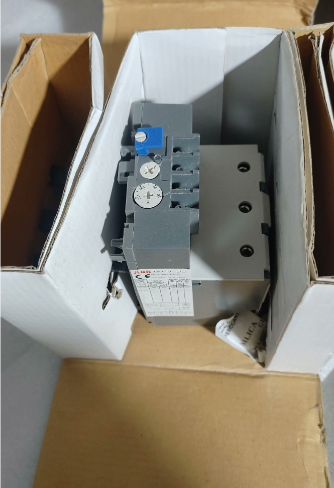

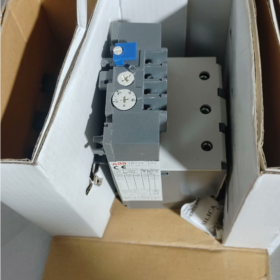
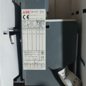
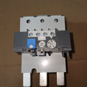
The TA110DU110 is a classic 3-pole تتابع الحمل الزائد الحراري من ايه بي بي سلسلة تا, delivering integrated protection for three-phase asynchronous motors with a rated current range of 80~110A. Adopting the inverse-time tripping principle of bimetallic strips, this relay comes standard with phase-loss protection and automatic ambient temperature compensation, with a trip class of Class 10A. It can be directly plugged onto ABB A/AE/AF95~110 series contactors or mounted independently on DIN rails. Equipped with switchable manual/automatic reset modes and one normally open (لا) plus one normally closed (نورث كارولاينا) auxiliary signal contact, it serves as a standard protective component for industrial motor control circuits. Widely applied to power loads such as fans, مضخات المياه, compressors and conveyor lines, it effectively prevents winding burnout accidents of motors caused by overload, locked rotor and phase loss.
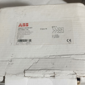
النموذج الكامل: `TA110DU110`
- مواجهة: General series code for ABB thermal overload relays, representing the family of electrothermal protective relays
- 110: تصنيف الإطار الحالي, indicating the maximum rated frame current of 110A for this product
- DU: Function type code, standing for standard specification featuring 3-pole protection, phase loss detection, ambient temperature compensation and direct mounting onto contactors
- 110: Upper limit of current setting, corresponding to an adjustable current range of 80A ~ 110A
المواصفات الفنية الأساسية
| فئة المعلمة | عنصر المعلمة | المواصفات التفصيلية |
| Main Circuit Characteristics | Rated Insulation Voltage Ui | 690الخامس و / 440في العاصمة |
| UL/CSA Rated Operational Voltage | 600الخامس و | |
| النطاق الحالي قابل للتعديل | Continuously adjustable from 80A to 110A | |
| فئة الرحلة | الفئة 10 أ (standard motor protection class) | |
| عدد البولنديين | 3 أقطاب, full 3-pole protection | |
| حماية فقدان المرحلة | Standard built-in; accelerates tripping under three-phase unbalance | |
| تعويض درجة الحرارة | المدعومة; protection accuracy remains unaffected within -25℃ ~ +55℃ ambient temperature | |
| جهات الاتصال المساعدة | تكوين الاتصال | 1 لا + 1 نورث كارولاينا, electrically isolated |
| Conventional Thermal Current Ith | 5أ | |
| Rated Contact Capacity | تيار متردد 250 فولت 3 أمبير; DC24V 5A | |
| ميكانيكية & تصاعد | طريقة التركيب | Direct mounting on contactors / independent DIN rail mounting |
| المقاولين المتوافقة | Series A95, A110, AE95, AE110, AF95, AF110 | |
| طريقة الأسلاك | Screw-clamp terminals | |
| Overall Weight | تقريبا. 0.76كجم | |
| وضع إعادة الضبط | Switchable manual/automatic reset; supports remote reset expansion | |
| بيئة & الشهادات | درجة حرارة التشغيل المحيطة | -25درجه مئوية ~ +55 درجه مئوية |
| درجة حرارة التخزين | -40درجه مئوية ~ +70 درجه مئوية | |
| تصنيف حماية الدخول | IP20 | |
| Compliance Certifications | م, أول, وكالة الفضاء الكندية, سي سي سي, جي إل (Germanischer Lloyd Marine Certification) | |
| Compliant Standards | اللجنة الانتخابية المستقلة 60947-4-1, في 60947-4-1 |
Cross Reference of Models within the Same Series
- Full Specifications of TA110DU Frame
| النموذج الكامل | النطاق الحالي قابل للتعديل | Compatible Motor Power (380V) | Matching Contactors |
| TA110DU-65 | 50 ~ 65A | 30كيلوواط | A95/AE95/AF95 |
| TA110DU-80 | 60 ~ 80A | 37كيلوواط | A95/AE95/AF95 |
| TA110DU-90 | 66 ~ 90A | 45كيلوواط | A110/AE110/AF110 |
| TA110DU-110 | 80 ~ 110A | 55كيلوواط | A110/AE110/AF110 |
- Comparison of Adjacent Frame Series
| نموذج السلسلة | الإطار المقدر الحالي | Maximum Adjustable Current | السيناريوهات القابلة للتطبيق |
| TA110DU | 110أ | 110أ | واسطة & small power motors (30~55kW) |
| TA200DU | 200أ | 200أ | واسطة & large power motors (75~110 كيلوواط) |
| TA450DU | 450أ | 450أ | High-power heavy-duty motors (132~250kW) |
سيناريوهات التطبيق النموذجية
- Standard Motor Starter Protection Circuit: Combined with ABB A/AF series contactors to form electromagnetic starters, connected in series to the main circuit of three-phase motors to realize protection against motor overload, locked rotor and phase loss. It is the standard protection solution for general power equipment including fans, مضخات المياه, air compressors and machine tool spindles.
- MCC Motor Control Centers: Served as standard protection units for motor feeder circuits in drawer cabinets and fixed cabinets, integrated with contactors to realize integrated motor start-stop control and protection.
- الناقل & Logistics Sorting Systems: Matched with roller motors and sorting drive motors, adapting to frequent start-stop and load fluctuation working conditions of production lines, and preventing motor aging and burnout caused by long-term overload.
- Central Air Conditioning & Refrigeration Units: Protect refrigeration power equipment such as compressors and cooling tower fans, suited to the refrigeration industry’s characteristics of severe load fluctuations and seasonal high-load operation.
- Support for OEM Complete Equipment: Widely matched with industrial machinery including packaging machinery, rubber & plastic machinery and metallurgical auxiliary equipment. As standardized motor protection components, it meets electrical safety specification requirements for equipment factory delivery.
مصفوفة استكشاف الأخطاء وإصلاحها المشتركة
| ظاهرة الخلل | تحليل السبب الجذري | حلول خطوة بخطوة |
| Relay falsely trips during normal motor operation | 1. Low current setting value, lower than the motor rated current | 1. Check the motor rated current and adjust the setting knob to the corresponding rated value |
| 2. Excessively high ambient temperature exceeding compensation range | 2. Improve cabinet heat dissipation and avoid direct sunlight or heat source radiation | |
| 3. Severe current deviation induced by three-phase voltage unbalance | 3. Measure three-phase currents to troubleshoot hidden risks of voltage unbalance or phase loss | |
| 4. Overlong motor startup time exceeding withstand limit of Class 10 trip class | 4. Replace with thermal overload relays of Class 20 أو الطبقة 30 for heavy-load startup applications | |
| Relay fails to trip under motor overload or locked rotor | 1. Excessively high current setting value, far higher than the motor rated current | 1. Recalibrate the setting value to strictly match the motor rated current |
| 2. Loose main circuit wiring terminals leading to excessive contact resistance | 2. Tighten main circuit terminals and troubleshoot overheating & oxidation issues | |
| 3. Stuck relay mechanical mechanism and failed tripping assembly | 3. Cut off power and manually test the flexibility of the tripping mechanism; replace the module if jamming occurs | |
| Protection does not activate upon phase loss fault | 1. Wrong three-phase incoming wiring with incomplete connection to relay main circuit | 1. Verify L1/L2/L3 three-phase wiring to ensure all phases are reliably connected |
| 2. Aging and failure of internal bimetallic components | 2. Artificially simulate phase loss to test protection function; replace the relay if function fails | |
| Abnormal or no output of auxiliary contact signals | 1. Auxiliary contact load exceeds rated capacity, resulting in contact burnout | 1. Confirm load current does not exceed contact rating; add intermediate relays for current amplification if necessary |
| 2. No reset after tripping, contacts remain in fault state | 2. Manually or automatically reset the relay after troubleshooting root fault causes | |
| 3. Poor contact due to contact oxidation | 3. Measure contact on-off resistance; replace the module if poor contact exists |
- Terminal Definition & وصف الوظيفة
The TA110DU110 adopts industry-standard terminal numbering rules, divided into two parts: main power circuit and auxiliary control circuit. All terminals are front-mounted screw-clamp type with all wiring operations accessible from the front side.
- Main Circuit Terminals (Three-Phase Power Circuit)
| علامة المحطة | نوع المحطة | تعليمات الأسلاك |
| 1L1, 3L2, 5L3 | المحطات الواردة | Upper-side input, connected to output terminals of contactor main contacts, corresponding to three-phase power L1/L2/L3 |
| 2T1, 4T2, 6T3 | المحطات الصادرة | Lower-side output, directly connected to stator windings of three-phase asynchronous motors |
ملحوظات: The three-phase main circuit has no polarity requirement, yet each phase must be connected in one-to-one correspondence without cross-phase misconnection. When directly mounted on contactors, the main circuit is automatically conducted via plug-in copper bars with no extra power wiring required.
- Auxiliary Circuit Terminals (يتحكم & Signal Circuit)
| علامة المحطة | نوع الاتصال | وصف الوظيفة | Typical Wiring Purpose |
| 95 – 96 | مغلق عادة (نورث كارولاينا) | Conductive under normal operating conditions; opens upon tripping caused by overload/phase loss | Connected in series to contactor coil control circuit to cut off power supply to the contactor and stop the motor upon faults |
| 97 – 98 | مفتوح عادة (لا) | Disconnected under normal operating conditions; closes upon tripping caused by overload/phase loss | Connected to sound-light alarm circuits or PLC digital input points for fault signal upload and alarm notification |
The auxiliary contacts are electrically isolated with no electrical connection to the main circuit and a conventional thermal current of 5A. Intermediate relays are recommended for series connection to expand capacity and prevent contact burnout when controlling high-power loads.
- Typical Wiring Schemes
- Direct Mounting Wiring on Contactor (الأكثر استخداما)
This is the standard application method for TA110DU110. It is directly plugged onto the top of ABB A95/A110/AF95/AF110 series contactors. The main circuit is automatically connected through internal plug-in connectors, with only the control circuit requiring external wiring:
- Three-phase power passes through a circuit breaker and connects to contactor main incoming terminals L1/L2/L3
- After the thermal overload relay is directly mounted on the contactor, the main circuit is automatically conducted without extra power wiring
- One end of the control power supply passes through stop and start buttons and connects to contactor coil terminal A1
- ال 95-96 NC contact of the thermal relay is connected in series to the live wire of the contactor coil circuit to realize automatic motor shutdown under overload
- ال 97-98 NO contact of the thermal relay is paralleled with fault indicator lights or connected to PLC DI points for fault alarming
- Independent DIN Rail Mounting Wiring
Independent rail mounting is adopted for separate installation or matching with contactors of other brands:
- Contactor output terminals L1/L2/L3 are connected to thermal relay incoming terminals 1L1/3L2/5L3 via power cables
- Thermal relay outgoing terminals 2T1/4T2/6T3 connect to motor three-phase terminals
- The control circuit follows the same wiring logic as the direct mounting scheme, with the 95-96 NC contact wired in series into the contactor coil circuit
احتياطات الأسلاك:
The cross-sectional area of main circuit cables shall match the 110A rated current; 25mm² copper cables are recommended
1~1.5mm² control cables are suggested for auxiliary control circuits
Reliable earthing is mandatory to guarantee personal and equipment safety
ثالثا. Parameter Comparison Table of Cross-Brand Equivalent Models
Below is a parameter comparison of mainstream thermal overload relays of the same current range from Siemens and Schneider Electric, for reference during alternative selection:
| عنصر المقارنة | ايه بي بي | شنايدر إلكتريك | سيمنز |
| النموذج الكامل | TA110DU110 | LRD3365C | 3RU5146-4MB1 |
| النطاق الحالي قابل للتعديل | 80 ~ 110A | 80 ~ 104A | 80 ~ 100A |
| الإطار المقدر الحالي | 110أ | 115أ | 140أ |
| فئة الرحلة | الفئة 10 أ | فصل 10 | فصل 10 |
| عدد البولنديين | 3 أقطاب | 3 أقطاب | 3 أقطاب |
| تكوين الاتصال المساعد | 1لا + 1نورث كارولاينا (electrically isolated) | 1لا + 1نورث كارولاينا (electrically isolated) | 1لا + 1نورث كارولاينا (electrically isolated) |
| حماية فقدان المرحلة | Standard built-in | Standard built-in | Standard built-in |
| Ambient Temperature Compensation | المدعومة (-25درجه مئوية ~ +55 درجه مئوية) | المدعومة (-20درجه مئوية ~ +60 درجه مئوية) | المدعومة (-20درجه مئوية ~ +60 درجه مئوية) |
| وضع إعادة الضبط | Switchable manual/automatic | Switchable manual/automatic | Switchable manual/automatic |
| Compatible Contactor Series | A95~A110, AF95~AF110 | LC1D95~LC1D115 | 3RT5045~3RT5046 |
| طريقة التركيب | Direct mounting on contactor / السكك الحديدية الدين | Direct mounting on contactor / السكك الحديدية الدين | Direct mounting on contactor / السكك الحديدية الدين |
| Compliance Certifications | م, أول, سي سي سي, جي إل | م, أول, سي سي سي | م, أول, سي سي سي |


 Impulse Heat-Sealing Temperature Controller")


")


NH42-63-318x560.png "مفاتيح النقل التلقائي من نوع الكمبيوتر الشخصي CHINT (المنشطات الأمفيتامينية)NH42-63/4SZ")


