 المقاولين,قاطع الدائرة,الاستشعار,التشفير,بلك,محول

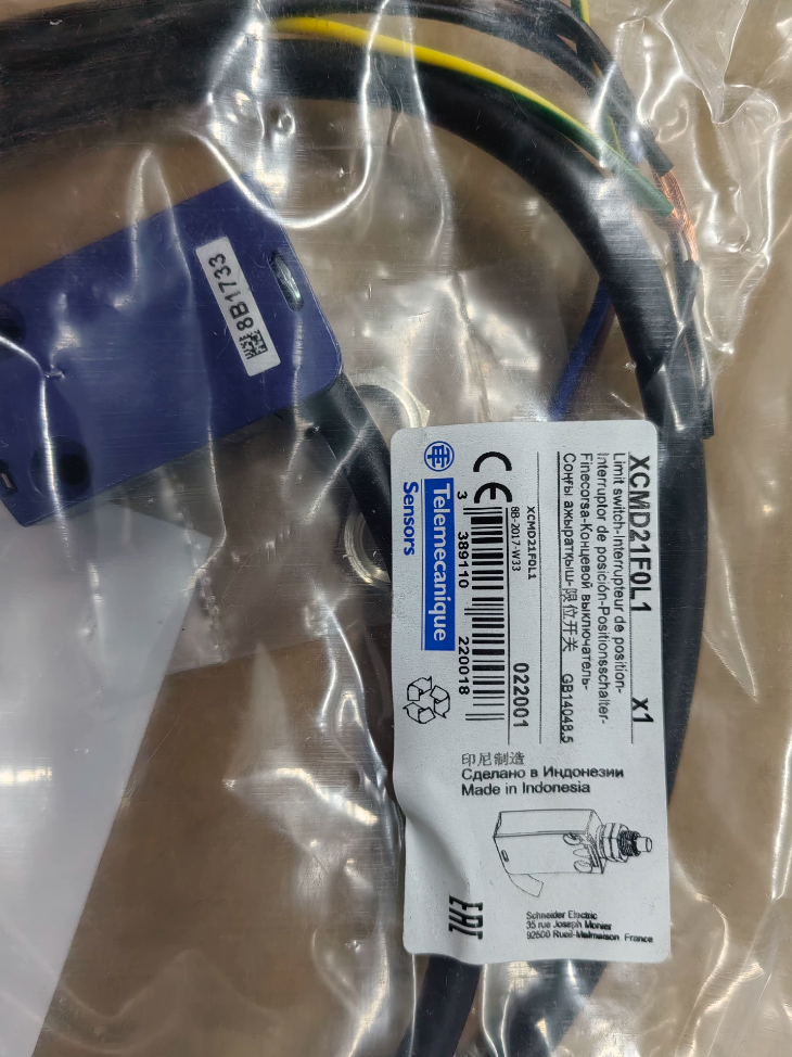

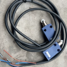
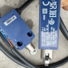
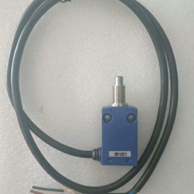
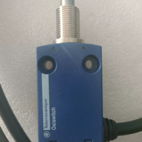
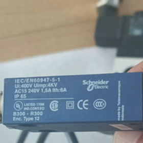
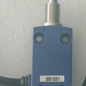
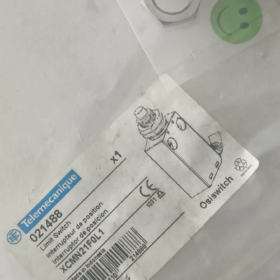
Important Notice: Officially Obsolete
End of commercialization: 30 Dec 2024; Direct official replacement model: XCMH21F0L1
- فك رمز النموذج
XCMN 21 F0 L1
- XCMN: OsiSense XC series, miniature plastic housing limit switch
- 21: Contact configuration → 1NO + 1نورث كارولاينا, snap action contacts
- F0: Operator code
F0 = M12 threaded metal end plunger, vertical unidirectional actuation, عودة الربيع
- L1: Cable specification → Factory-fitted fixed cable, 1 م الطول, 4×0.75 mm² PVR cable
- الكهربائية الأساسية & المواصفات الميكانيكية
| غرض | المعلمة |
| نموذج الاتصال | 1 مفتوح عادة + 1 مغلق عادة, snap action (positive opening) |
| Rated Insulation Voltage Ui | 300 V |
| AC-15 Utilization Category | 240 V / 1.5 أ |
| DC-13 Utilization Category | 250 V / 0.1 أ; الأعلى. 3 W at 24 في العاصمة |
| التحمل الميكانيكي | 5,000,000 العمليات |
| حماية الدخول | IP65, IK04 |
| درجة حرارة التشغيل | -25 ℃ ~ +70 درجه مئوية; تخزين: -40 ℃ ~ +70 درجه مئوية |
| Minimum Operating Force | 8.5 ن |
| طريقة التركيب | M12 threaded head with lock nut (panel mounting) |
| كابل | 4-core, أسود / Black-White / بني / أزرق |
| مادة | السكن: Engineering plastic; الغطاس: Zamak alloy |
- Cable Wiring Definition (4-core fixed cable)
أسود (BK): COM Common terminal
Black-White (BK-WH): NC Normally Closed (conducted at rest)
بني (BR): NO Normally Open (open at rest)
أزرق (BU): Spare unused wire
- Obsolete Replacement Solutions
✅ Preferred Direct Replacement: XCMH21F0L1
Identical operator, contact layout, cable length and mounting dimensions
Upgraded XCMH series with minor housing optimization, same protection rating. Direct interchange without panel modification or wiring change.
Priority procurement model: XCMH21F0L1
⚠️ Alternative Compatible Models (Verify working conditions before selection)
XCMN21F0L2: Identical construction, 2 م كابل (only cable length differs)
XCMD21F0L1: Standard large XC series; أبعاد تركيب مختلفة, NOT directly interchangeable for panel installation
- سيناريوهات التطبيق النموذجية
صغير الأتمتة معدات, آلات التعبئة والتغليف, conveyor lines, light-duty machine tools, pneumatic actuator limit detection, equipment guard position monitoring. Suitable for panel mounting in confined installation spaces.
- Critical Installation Prohibitions
- Do not support the switch by cable tension; the switch body must be securely fixed.
- The plunger shall only be actuated axially and vertically. Lateral force or angled impact is forbidden.
- Never compress the plunger beyond its maximum travel limit to avoid internal mechanical damage.
- Not recommended for heavy dust, persistent condensation or corrosive environments. Upgrade to XCMD metal housing series if such conditions exist.
إذا لزم الأمر, أستطيع أن أقدم:
- Dimension comparison table between XCMH21F0L1 and XCMN21F0L1
- Text version of outline dimensions
- Contact electrical schematic
Complete Installation Instruction – شنايدر XCMN21F0L1 (M12 End Plunger Limit Switch)
ملحوظة: This switch adopts panel feed-through mounting via M12 threaded head. The replacement model XCMH21F0L1 shares identical installation procedures and dimensions.
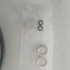
Key mounting parameters: Panel cutout Φ12.5 mm; Maximum allowable panel thickness 8 مم; Supplied M12 lock nut, سماكة 3.5 مم.
سلامة ما قبل التثبيت & إعداد الأداة
- الأدوات المطلوبة
Open-end / ring spanner for M12 nut. Do not clamp the plastic housing directly with pliers.
المتعدد (continuity test for contact verification post-installation)
Tape measure, marker; rubber buffer stop optional
- التفتيش قبل التثبيت (إلزامي)
- فحص بصري: No housing cracks, smooth plunger movement, intact cable sheath.
- Manual plunger test: Fast automatic spring return without jamming.
- Confirm working condition: Only axial vertical compression permitted; lateral impact prohibited.
- Power isolation! No live wiring or commissioning.
- إجراءات التثبيت الميكانيكية (Panel Embedded Mounting)
خطوة 1: Machine panel cutout
Standard cutout diameter: Φ12.5 mm
Allowable panel thickness: 0 ~ 8 مم (cannot be tightened if thicker)
Deburr cutout edges; sharp burrs scratch threads and seals, compromising IP65 protection.
خطوة 2: Remove lock nut and feed switch through panel
- Unscrew the M12 lock nut from the plunger threaded end.
- Insert the plunger through the Φ12.5 cutout from the outer actuation side of the panel, leaving the switch housing inside the panel.
❌ Reverse mounting (housing outside) will invalidate waterproof protection.
خطوة 3: Lock and secure (Critical Step)
- Fit the M12 lock nut on the inner side of the panel and pre-tighten manually.
- Tighten moderately with spanner, Recommended torque: 1.0~1.5 N·m
⚠️ Overtightening is strictly prohibited! Excessive torque deforms plastic housing, causes internal jamming and seal failure.
- Shake the switch lightly after tightening: No rotation or looseness.
قاعدة التثبيت: Secure the switch solely via the M12 lock nut. Never pull the cable to support the unit!
خطوة 4: Cable routing (Ensure IP65 and cable service life)
1 m fixed cable exits from the bottom of the switch:
Reserve natural slack; avoid taut straight routing.
Prevent sharp 90° bends; minimum bending radius ≥ 5× cable outer diameter.
Install cable clamps away from the switch body to eliminate continuous friction under vibration.
- Actuator Stop Block Travel Adjustment (Common Source of Faults)
XCMN21F0L1: Straight plunger, عودة الربيع
Minimum operating force: 8.5 ن
Do not bottom the plunger at full travel!
✅ Standard adjustment procedure:
- Move the machine actuator slowly, let the stop block compress the plunger vertically.
- After contact switching occurs, maintain 0.5~1.5 mm overtravel margin.
- Mechanical hard stop must engage before the plunger reaches its full travel limit.
❌ Forbidden: Permanent hard bottoming of the plunger, repeated impact will destroy internal mechanism.
مُستَحسَن: Flat contact surface perpendicular to plunger axis. If inclined contact is needed, angle ≤30° to reduce impact load.
ثالثا. Cable Wiring Definition & Wiring Procedure
4-core fixed cable: 4×0.75 ملم²
| Wire Color | تعيين | وصف الوظيفة |
| Black BK | COM Common | Common signal terminal |
| Black-White BK-WH | NC Normally Closed | Conducted when plunger is released |
| Brown BR | NO Normally Open | Conducted when plunger is depressed |
| Blue BU | Spare Wire | Internally unconnected; insulate separately |
عملية الأسلاك
- Strip insulation length 5~6 mm, avoid loose strands.
- Terminate to relay / PLC terminals with firm clamping.
- Isolate the spare blue wire individually; prevent short-circuit with other conductors.
- Separate signal wiring from power cables to reduce electromagnetic interference.
- Pre-Power Verification Procedure
- Continuity test at rest (plunger released):
BK ↔ BK-WH conductive; BK ↔ BR open circuit
- Manually depress plunger gently (no violent impact):
BK ↔ BK-WH open circuit; BK ↔ BR conductive
- Release plunger; contacts recover instantly without delay or sticking.
- Repeat operation 10 times to confirm stable switching before connecting to control system.
- Installation Forbidden Practices (Cause Premature Switch Failure)
- ❌ Lateral force or angled impact on plunger; only axial vertical compression allowed
- ❌ Over-torque lock nut, cracking plastic housing
- ❌ Permanent hard bottoming of plunger via stop block
- ❌ Relying on cable tension to fix the switch
- ❌ Forcing threads through undersized cutout, damaging seals
- ❌ Sharp cable bends or persistent sheath friction
- ❌ Operation outside -25℃~+70℃; continuous immersion in water not allowed
- Routine Inspection Checklist During Operation
- Periodically check lock nut for loosening under vibration
- Inspect cable sheath for abrasion and cracking
- Clean dust/oil contamination on plunger; do not apply lubricant
- Readjust stop block travel if contact chatter occurs
Application Scenarios – Schneider XCMN21F0L1 Straight Plunger Miniature Limit Switch
Key characteristics recap: M12 threaded panel mounting, IP65, 1NO+1NC snap contacts, 1 m factory cable, حجم صغير, عودة الربيع. Designed for axial vertical actuation; unsuitable for heavy impact or lateral load. Obsolete replacement: XCMH21F0L1.
- الصناعات المعمول بها & المعدات النموذجية
- ماكينات التعبئة والتغليف (Primary Application)
رَأسِيّ / ماكينات التعبئة والتغليف الأفقية: Low-level material detection, cylinder stroke limit for pusher
ختم & hot-press machines: Confirm full closure of pressing plate, position safety signal
Carton erectors & sealers: Baffle position detection, carton presence sensing
Bag-making machines: Film deviation limit, home position detection for cutting blade
ملاحظات العملية: Low-speed reciprocating actuation, mild dust environment. Rigid stop blocks detect cylinder travel.
- Automated Conveying & Logistics Equipment
Light belt conveyors, roller lines: Limit position for lifting baffles, sorting flap feedback
Transfer units, small linear slides: Home limit, end-of-travel limit
Box stop mechanisms: Confirm engagement of stopping cylinder
تذكيرات: Install rubber buffers for high-speed heavy conveyor applications to avoid plunger impact damage.
- Pneumatic Tooling & Machine Tool Auxiliaries
Pneumatic clamping fixtures: Feedback signal for clamped/released state
Rotary tooling, light indexing units: Mechanical home position detection
Limit detection for small mold core pulling mechanisms
- Light Industry Automation Equipment
Injection molding peripheral robots, small pick-and-place stroke limits
معدات الطباعة: Paper baffle limit, roller frame position detection
Lithium battery / 3C automation: Limit sensing for miniature linear slides
- Guard & Safety Interlock Mechanisms
Equipment access panel / maintenance door position detection (door closed confirmation signal)
Lock confirmation for small protective covers
⚠️ If used for safety stop circuits: Verify positive-opening contacts. Specially certified safety limit switches are recommended for high safety integrity levels.
- Light-Duty Food & المعدات الصيدلانية (جاف, Dust-Free Environments)
Position feedback for small hopper gate opening/closing
Limit detection for light conveyor diverting baffles
القيد: Plastic housing; prolonged exposure to strong acid/alkaline cleaning agents prohibited. Not suitable for frequent high-pressure washing.
- Auxiliary Mechanisms for Construction & الآلات الزراعية
Stroke feedback for small hydraulic/pneumatic actuators
Position detection for light-duty baffles and material gates (dry operating conditions)
- Recommended Operating Conditions
- Confined installation space requiring M12 threaded panel mounting
- Actuation mode: Vertical axial compression with smooth contact from stop block
- Moderate actuation frequency (≤10 cycles/min), no continuous heavy impact
- Indoor environment with light dust and splash water, IP65 adequate
- Control demand: Simultaneous NO + NC output for dual-channel PLC signal verification
- Simplified wiring requirement; preference for pre-terminated factory cable instead of field wiring
ثالثا. Unsuitable Working Conditions (Selection Risk Avoidance)
- ❌ Lateral impact or angled compression of plunger (accelerates internal failure)
- ❌ Continuous heavy spray, permanent immersion, heavy condensation (IP65 ≠ waterproof immersion)
- ❌ Corrosive atmosphere (acid/alkali vapor, organic solvents)
- ❌ Continuous high-frequency impact (tens of cycles per minute, shortens mechanical life)
- ❌ Heavy machinery without shock absorption causing rigid impact
- ❌ Long-term outdoor installation without weather protection
- ❌ Applications requiring lever / roller actuators (this model is straight plunger; select corresponding XCMN actuator heads if needed)
- Typical Control Schemes
- Cylinder position feedback: Switch NO signal to PLC. Trigger next process upon cylinder full extension. NC contact used for fault signal verification.
- Travel soft limit: Halting motor/cylinder when slide reaches set position.
- Access panel monitoring: Plunger depressed when guard closed to enable machine operation; open contact triggers alarm when guard is opened.



NH42-63-318x560.png "مفاتيح النقل التلقائي من نوع الكمبيوتر الشخصي CHINT (المنشطات الأمفيتامينية)NH42-63/4SZ")



