 المقاولين,قاطع الدائرة,الاستشعار,التشفير,بلك,محول

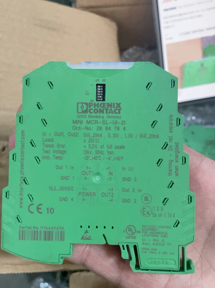

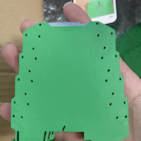
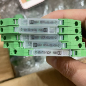
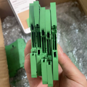
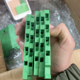
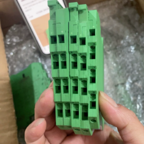
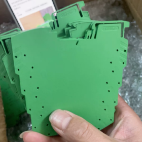

النموذج الكامل:ميني MCR-SL-UI-2I
فينيكس اتصل بمعزل الإشارة التناظرية (مكرر الإشارة), جبل السكك الحديدية DIN, 1-مدخلات القناة, 2-قناة معزولة الإخراج الحالي
المعلومات الأساسية
| غرض | المعلمة |
| رقم الطلب. | 2864794 |
| سلسلة المنتجات | ميني إم سي آر-SL |
| عرض السكن | 6.2 ملم فائق النحافة |
| تصاعد | السكك الحديدية DIN-35 |
| الأسلاك | محطات المسمار |
| مزود الطاقة | 24 VDC |
| عزل | المدخلات والمخرجات وإمدادات الطاقة عزل ثلاثي الاتجاه |
مواصفات الإشارة
مدخل (DIP التبديل شكلي):0-20أماه / 4-20أماه / 0-10V / 1-5V
اثنين من النواتج الحالية المستقلة:0-20أماه / 4-20أماه. يتم عزل المخرجين بشكل متبادل من أجل الحصول عليهما في وقت واحد بواسطة أنظمة PLC وأنظمة التسجيل.
وظائف:عزل الإشارة, 1-تقسيم الإشارة إلى -2, مكافحة التدخل, عزل فرق الجهد, تحويل الإشارة & النسخ المتماثل
دقة:نموذجي <0.1%
طلب:تقسيم إشارة المرسل; يتم تغذية إشارة مستشعر واحدة في وقت واحد إلى وحدة التحكم والعرض / أجهزة التسجيل
سيناريوهات التطبيق النموذجية
- حلقة تناظرية بتقنية الذكاء الاصطناعي 1 في 2 خارج: مستشعر واحد 4-20 مللي أمبير متصل بكل من وحدة PLC AI والمسجل اللاورقي
- عزل الفرق المحتمل بين الأجهزة الميدانية وخزانة التحكم للتخلص من تداخل الحلقة الأرضية
- تركيب عالي الكثافة في خزانات مدمجة ذات مبيت نحيف مقاس 6.2 مم
استبدال & البدائل المرجعية
استبدال داخل السلسلة: التحقق من أنواع المدخلات والمخرجات. رقم الجزء هذا ليس قديمًا; كل من الوحدات الجديدة والمستعملة متوفرة في السوق.
ما يعادلها المحلية: عازل إشارة DIN للسكك الحديدية, 1-مدخل 2-خارج 4-20 مللي أمبير
إرشادات استكشاف الأخطاء وإصلاحها
- لا يوجد إخراج: تحقق من مصدر الطاقة 24VDC; تأكد من أن نطاق إدخال مفتاح DIP يطابق إشارة المجال.
- إخراج غير دقيق: تحقق من مقاومة تحميل الحلقة; الأعلى. تحميل الإخراج الحالي تقريبا. 500 أوه.
- تقلب الإشارة: التحقق من سلامة العزل الثلاثي; فحص ظروف التأريض الميداني.
سيناريوهات تطبيق فاصل الإشارة المعزل
فاصل إشارة المعزل (1-المدخلات والمخرجات المتعددة, نموذجي 1 في 2 خارج مثل فينيكس 2864794 ميني MCR-SL-UI-2I). القدرات الأساسية: عزل كلفاني لقمع الحلقة الأرضية + تكرار إشارة تناظرية واحدة إلى مخرجات مستقلة متعددة. تستخدم بشكل رئيسي للحلقات التناظرية الصناعية 4-20 مللي أمبير و0-10 فولت.
- تقسيم الإشارة لاقتناء أنظمة متعددة (الأكثر شيوعًا)
تعمل إشارة مستشعر واحدة على تغذية مجموعتين من المعدات دون تأثير متبادل
- أجهزة الإرسال الميدانية (ضغط, مستوى, درجة حرارة, تدفق, 4-20 أماه) → قناة واحدة لوحدة PLC AI, الآخر إلى مسجل رقية, المؤشر الرقمي أو نظام DCS.
- يتم توجيه إشارة ردود الفعل الخاصة بموضع الصمام إلى كل من المؤشر المحلي ونظام التحكم.
سيؤدي الاتصال المتوازي المباشر بدون فاصل المعزل إلى توهين الإشارة, انحراف القياس والصراع الأرضي المحتمل بين الأجهزة.
- قمع التدخل في الحلقة الأرضية للانجراف / إشارات الرعشة
الأدوات الميدانية, يمكن توصيل PLC و DCS بنقاط أرضية منفصلة. يؤدي الاختلاف المحتمل بين نقاط التأريض إلى إنشاء حلقات أرضية, مما أدى إلى غضب الإشارة التناظرية, انجراف نقطة الصفر وقراءات غير مستقرة.
يوفر المعزل الفاصل عزلًا كلفانيًا بين المدخلات, المخرجات وإمدادات الطاقة لكسر الحلقات الأرضية.
الصناعات النموذجية: خطوط الإنتاج على نطاق واسع, معالجة المياه, علم المعادن, محطات توليد الطاقة ذات كابلات الإشارة التناظرية الطويلة.
- واجهة الإشارة بين الأنظمة المستقلة
تبادل الإشارات التناظرية بين أنظمة التحكم المختلفة:
يتم إرسال الإخراج التناظري من PLC-A إلى PLC-B وأجهزة الطرف الثالث, حيث يكون لدى كلا النظامين شبكات تأريض منفصلة ولا يمكنهما مشاركة أرضية مشتركة.
ملحوظة: إن المقسمات العازلة القياسية ليست آمنة في جوهرها. حدد نماذج معتمدة من IS لنقل إشارة أداة المنطقة الخطرة إلى خزانات غير خطرة.
- تحويل الإشارة المجمعة & تقسيم
تحويل مدخلات الجهد إلى مخرجات تيار متعددة, أو تحويل مدخلات 4-20 مللي أمبير إلى مخرجات متعددة 0-10 فولت; تحقيق تحويل تنسيق الإشارة مع النسخ المتماثل متعدد القنوات.
مثال: تم تحويل إشارة الضغط الميدانية 0-10 فولت إلى مخرجين 4-20 مللي أمبير لوحدات الاستحواذ عن بعد.
- حماية المعدات ضد التداخل المفاجئ في الوضع الشائع
عندما تعمل الكابلات التناظرية بجانب كابلات الطاقة, يؤدي تبديل المحرك وVFD إلى توليد تداخل في الوضع الشائع وارتفاعات عابرة. يعمل العزل على منع التداخل من الدخول إلى بطاقات PLC AI, حماية وحدات الإدخال باهظة الثمن وتقليل مخاطر الفشل.
- تركيب عالي الكثافة في خزائن التحكم المدمجة
وحدات ذات عرض نحيف مثل سلسلة Phoenix MINI (6.2 مم) السماح بتركيب سكة DIN الكثيفة للخزائن الصغيرة والتعديلات التحديثية للخزانة دون استهلاك مساحة خزانة زائدة.
- مشاريع تحديث المصنع
أضف نظام مراقبة جديدًا دون تعديل أسلاك المستشعر الموجودة. تثبيت المعزل الفاصل لتكرار الإشارة; لا يلزم استبدال الأداة الميدانية.
التمييز بين الأجهزة المماثلة
- فاصل إشارة المعزل: 1-المدخلات والمخرجات المتعددة, ينفذ النسخ المتماثل للإشارة وتقسيمها
- عازل الإشارة: 1-داخل 1 خارج, يوفر العزلة & التحويل دون تقسيم الإشارة
- محول الإشارة: ينفذ تحويل الجهد الحالي, قد تفتقر إلى العزلة الكلفانية ولا يمكنها تكرار مخرجات متعددة
ملاحظات التطبيق
- تتمتع قنوات الإخراج الحالية بحدود قصوى لمقاومة الحمل; الزائد يسبب تشويه الإشارة.
- اضبط مفاتيح DIP لتتناسب مع نوع إشارة الإدخال الفعلية (4-20 أماه / 0-10 V).
- للبيئات المعرضة لخطر الانفجار, استخدام نماذج معتمدة آمنة جوهريًا; لا يجوز استخدام الفواصل العازلة للأغراض العامة في حلقات المناطق الخطرة.
مبدأ العمل لفاصل الإشارة المعزل
خذ فينيكس 2864794 (ميني MCR-SL-UI-2I), فاصل عازل ثلاثي الاتجاه معزول 1 في 2 خارج كمثال.
المبدأ الأساسي: لا يوجد اتصال موصل مباشر بين المدخلات, إمدادات الطاقة والمخرجات. يتم نقل الإشارات عبر الاقتران المغناطيسي أو البصري, بينما يتم نسخ إشارة تناظرية خام واحدة إلى عدة مخرجات تناظرية مستقلة.
أربع كتل وظيفية: تكييف الإدخال ← اقتران العزل ← دائرة تكرار الإشارة ← وحدة إخراج متعددة القنوات, بالإضافة إلى مصدر طاقة معزول.
- تكييف إشارة الإدخال
الإشارات التناظرية الميدانية (4-20 أماه, 0-10 الخامس إلخ.) أدخل دائرة الإدخال:
تحدد مفاتيح DIP نوع الإشارة ونطاق القياس.
تقوم دوائر التصفية بقمع الضوضاء عالية التردد; يحول التحويل IV التيار الوارد إلى إشارة جهد داخلي.
يؤدي أخذ العينات إلى توليد جهد داخلي يتناسب مع حجم الإدخال.
يتم عزل جانب الإدخال جلفانيًا عن الدوائر اللاحقة.
- اقتران العزلة (مرحلة العزلة الأساسية)
تعتمد مضخمات العزل الصناعية عالية الدقة في الغالب على الاقتران المغناطيسي (عزل المحولات), قد تستخدم الوحدات الأقدم قارنات التوصيل الضوئية.
يتم تعديل الإشارة التناظرية المشروطة على حامل تيار متردد عالي التردد.
تنتقل الإشارة عن طريق المجال المغناطيسي من خلال محول عزل مصغر; لا يوجد مسار نحاسي موصل بين اللفات الأولية والثانوية.
المحول الأساسي ينتمي إلى جانب الإدخال; الثانوي ينتمي إلى جانب الإخراج. يتم كسر مسارات الحلقة الأرضية ويتم حظر اختلافات الجهد الأرضي عبر المواقع.
يمر مصدر الطاقة أيضًا من خلال محول عزل مستقل لتغذية دوائر الإخراج, تحقيق العزلة الثلاثية: مدخل, الإخراج وإمدادات الطاقة.
⚠️ تظهر قارنات التوصيل الضوئية العامة خطيًا ضعيفًا. تنشر سلسلة MCR عالية الدقة عزلًا مغناطيسيًا لضمان دقة بمستوى 0.1%.
- إزالة التشكيل & استعادة الإشارة
تتم إزالة تشكيل الموجة الحاملة عالية التردد التي تمر عبر حاجز العزل, استعادة الإشارة المرجعية التناظرية المماثلة في الحجم لإدخال المجال الأصلي.
- استنساخ الإشارة (وظيفة الفاصل المحددة)
تميز هذه المرحلة الفاصل عن العوازل العادية أحادية القناة.
تعمل دوائر المضخم التشغيلي عالية الدقة على إنشاء قناتين مستقلتين لمحرك الإخراج من إشارة مرجعية واحدة:
يتم عزل قناتين للإخراج جلفانيًا عن بعضهما البعض.
تقوم كل قناة بشكل مستقل بتوجيه الأحمال النهائية (بلك, مسجل, مؤشر رقمي).
لن تؤثر الدائرة القصيرة أو الخطأ في أحد المخرجات على المخرج الآخر أو مدخل مستشعر المجال الأصلي.
عازل عادي 1 في 1 خارج: مرحلة واحدة فقط لسائق الإخراج.
المعزل الخائن: دوائر تشغيل النسخ المتماثل الإضافية متعددة القنوات.
- برنامج تشغيل الإخراج متعدد القنوات
يتم تحويل الإشارات المرجعية المكررة إلى التيار (4-20 أماه / 0-20 أماه) أو مخرجات الجهد للمعدات النهائية.
تخضع المخرجات الحالية لقيود مقاومة الحمل القصوى; تؤدي مقاومة الحمل المفرطة إلى إخراج مشوه.
ملخص مبسط
بدلاً من موازاة إشارة مستشعر واحدة بشكل مباشر مع جهازي استقبال (مما يسبب أخطاء في تقاسم التيار والتداخل المحتمل على الأرض), يقرأ المعزل الفاصل الإشارة الواردة, يوفر فصل كلفاني من الجانب الميداني, ينشئ داخليًا إشارتين جديدتين متطابقتين ويغذيهما بشكل منفصل لنظامين. يحتاج المستشعر فقط إلى تشغيل المعزل كحمل منفرد.
مبدأ قمع الحلقة الأرضية
تتصل الأداة الميدانية بالنقطة الأرضية A; يتصل PLC بالنقطة الأرضية B. قد يصل فرق الجهد بين A وB إلى عشرات الفولتات. تخلق الأسلاك المباشرة تيارًا متداولًا في خطوط الإشارة وتنتج ارتعاشًا للقياس. يقوم محول العزل بكسر المسار الموصل بين الأرض من جانب الإدخال والأرض من جانب الإخراج, القضاء على تعميم حلقة الأرض الحالية.
جدول مقارن
| جهاز | المبدأ الرئيسي |
| عازل الإشارة | عزل جانب الإدخال, إخراج واحد, لا يوجد تكرار للإشارة |
| عازل الإشارة - الخائن | عزل كلفاني + تكرار الإشارة الداخلية لمخرجات مستقلة متعددة |
| محول الإشارة | تحويل الجهد الحالي, لا يوجد عزل كلفاني مضمون |
الملاحظات الرئيسية
- يمنع العزل تداخل الوضع الشائع ولكنه لا يمكنه إزالة الضوضاء الكامنة في الإشارة الأصلية. لا تزال هناك حاجة إلى فصل الأسلاك التناظرية عن كابلات الطاقة.
- تتطلب الوحدات المعزولة مغناطيسيًا 24VDC خارجيًا للحصول على طاقة مساعدة معزولة.
- يتم نسخ المخرجات متعددة القنوات إلكترونيًا داخليًا, ليس تحويلًا متوازيًا بسيطًا لحلقة الإدخال.
مواصفات عزل الجهد لفينيكس 2864794 (ميني MCR-SL-UI-2I)
عزل رباعي: مدخل, الإخراج-1, يتم عزل الإخراج 2 وإمدادات الطاقة بشكل متبادل; العزل الأساسي حسب EN61010.
| غرض | قيمة | ملاحظات |
| اختبار الجهد العازل | 1.5 كيلو فولت تيار متردد, 50 هرتز, 1 دقيقة | اختبار نوع المصنع; ينطبق على الإدخال إلى الإخراج, مدخلات الطاقة, الإخراج إلى الطاقة وبين قناتي الإخراج. |
| تصنيف الجهد العزل واجهة المستخدم | 50 الخامس التيار المتناوب/تيار مستمر | الحد الأقصى لجهد الوضع المشترك المستمر المسموح به عبر حاجز العزل; وليس اختبار الجهد على المدى القصير. |
| فئة العزل | العزل الأساسي | للأداة المضادة للتداخل فقط. ليس لحماية السلامة الشخصية. |
كثيرا ما يساء فهم التمييز النقدي في الموقع:
- 1.5 كيلو فولت تيار متردد/1 دقيقة جهد الاختبار: مصنع قصير المدة يتحمل قيمة الاختبار. لا تقم بتطبيق 1500 فولت بشكل مستمر عبر حاجز العزل أثناء التشغيل.
- تصنيف جهد العزل Ui = 50V AC / DC: الحد الأقصى المسموح به على المدى الطويل لفرق الجهد في الوضع المشترك عبر العزلة. يفضل أن يظل فرق الجهد الأرضي أقل بكثير من 50 فولت.
الصناعة-المعزل النموذجي-عزل الفاصل-مقارنة الجهد
| نوع النموذج | اختبار الجهد العازل | تصنيف الجهد العزل | ملحوظات |
| سلسلة فينيكس MINI-SL (2864794) | 1.5 كيلو فولت تيار متردد / 1 دقيقة | 50 الخامس التيار المتناوب/تيار مستمر | نحيف للغاية 6.2 ملم, العزلة الأساسية لأداة العملية المضادة للتدخل |
| سلسلة محسنة من الجيل الجديد من طراز MINI‑2 من Phoenix | 2.5 كيلو فولت تيار متردد / 1 دقيقة | 300 الخامس التيار المتناوب/تيار مستمر | عزل مقوى من أجل اختلافات أكبر في إمكانات الأرض |
| عازل منزلي عام | 1.5– 2 كيلو فولت تيار متردد / 1 دقيقة | 250 الخامس التيار المتردد | 250 يشير V إلى جهد العزل المقنن لمعظم المنتجات المحلية |
إرشادات التطبيق الهندسي
- تمنع هذه الوحدة تداخل الحلقة الأرضية والوضع الشائع فقط وليست جهاز عزل آمن. يجب ألا تتجاوز إمكانات حاجز العزل المتقاطع على المدى الطويل 50 فولت. حدد نماذج العزل المعزز إذا كان فرق الجهد الأرضي للموقع يتجاوز 50 فولت في كثير من الأحيان.
- 1.5 تنطبق كيلو فولت فقط على اختبار التحمل لفترة قصيرة; يمكن التسامح مع ارتفاعات الجهد العالي العابرة ولكن يحظر التشغيل المستمر للجهد العالي.
- تعريف العزل الرباعي: مدخل, الإخراج-1, يتم عزل مصدر الطاقة الناتج 2 و 24 فولت بشكل زوجي. لن تؤثر الدائرة القصيرة في أحد المخرجات على إشارة الإخراج أو الإدخال الأخرى.
العلاقة بين جهد العزل ودرجة الحرارة المحيطة لفاصل عازل الإشارة
التحليل على أساس فينيكس 2864794 ميني MCR-SL-UI-2I. التفريق بين جهد العزل المقدر (عملية طويلة الأمد), عازلة تحمل اختبار الجهد (1-اختبار قصير المدى لمدة دقيقة), and intrinsic breakdown voltage of insulating material.
- Datasheet-published parameters are temperature-independent within rated operating range
1.5 kV AC /1 min dielectric withstand test: Performed at reference 25 °C for factory type-approval only, not operational continuous voltage.
Rated insulation voltage Ui = 50 V AC/DC: Maximum allowable continuous common-mode voltage across isolation barrier. Within full published operating temperature range (-20 °C ~ +60 °C), datasheet parameters require no temperature-derating.
✅ Apply datasheet values directly when module operates within specified temperature range. Do not arbitrarily derate Ui to a lower value merely because cabinet temperature rises to 45 °C.
- Physical mechanism: Insulating-material breakdown voltage decreases at higher temperature
Isolation is realized by insulating dielectrics inside miniature pulse transformers (polymer films, magnet-wire enamel coatings).
Rising ambient temperature increases molecular mobility inside insulation materials; intrinsic material breakdown voltage declines, and instantaneous high-voltage withstand capability drops.
Industrial modules are designed with substantial safety margin: within -20 °C ~ +60 °C, real-world breakdown margin remains far above 1500 V test level; hence datasheet does not publish derating curves.
When ambient temperature continuously exceeds maximum rated +60 °C: Insulation aging accelerates; practical withstand capability degrades significantly. Long-term over-temperature operation raises risk of isolation-barrier failure and ground-loop-suppression loss.
⚠️ Distinguish clearly: Signal accuracy / temperature drift ≠ isolation withstand capability. Temperature-dependent measurement drift arises from signal-processing circuitry; isolation-voltage performance depends on dielectric materials, these are independent metrics.
- Temperature-dependence comparison table
| المعلمة | Behavior within ‑20~+60 °C rated range | Condition above +60 °C over‑temperature |
| 1.5 kV AC 1 min (dielectric test) | Datasheet value unchanged; physical safety margin of insulation reduces | Instantaneous high‑voltage withstand capability drops; dielectric test may fail |
| تصنيف الجهد العزل واجهة المستخدم (50 V for this model) | No datasheet‑mandated derating; use full Ui rating | Insulation aging accelerates; continuous full‑Ui operation is not recommended |
| Signal accuracy / thermal drift | Measurement error varies with temperature (tens of ppm/°C) | Measurement error further increases |
- Practical on-site engineering guidance (for MINI-SL series such as 2864794)
- Maintain module surrounding temperature between -20 °C ~ +60 °C. Within this range, apply datasheet values of 1.5 kV test withstand and 50 V rated insulation voltage without manual derating.
- If cabinet cooling is poor and module ambient temperature persistently exceeds +60 °C:
Immediate failure is not guaranteed, yet insulation aging accelerates and safety margin shrinks. Ground-loop-rejection performance deteriorates; long-term isolation-failure risk rises. Improve cabinet ventilation or adopt MINI-2 wide-temperature-range series.
- يمثل جهد العزل المقدر Ui=50V حدًا صعبًا للتطبيق, بغض النظر عن درجة الحرارة. يفضل أن يظل فرق الجهد الأرضي عبر الحاجز أقل بكثير من 50 فولت. إذا كان فرق الجهد الأرضي في الموقع يقترب بانتظام أو يتجاوز 50 فولت, لا تعتمد على التبريد للتخفيف; الترقية إلى نموذج واجهة المستخدم الأعلى على سبيل المثال. سلسلة MINI MCR-2 مع واجهة المستخدم = 300 فولت.
- عملية درجة حرارة منخفضة (-20 درجة مئوية): تتحسن قدرة تحمل العزل بشكل طفيف دون أي آثار سلبية.
- المفاهيم الخاطئة الشائعة
❌مفهوم خاطئ: عند درجة حرارة الخزانة 45 درجة مئوية, يمكن التعامل مع تصنيف اختبار 1.5 كيلو فولت على أنه جهد تشغيلي مستمر, السماح بـ 1000 فولت عبر حاجز العزل.
✔ التصحيح: 1.5 كيلو فولت هي قيمة اختبار مدمرة قصيرة الأمد في المصنع ويجب ألا يتم تطبيقها بشكل مستمر أثناء التشغيل تحت أي درجة حرارة. قم دائمًا بالرجوع إلى واجهة المستخدم الخاصة بجهد العزل المقنن لمعرفة ظروف الخدمة المستمرة.
❌مفهوم خاطئ: قم بتطبيق عامل التخفيض النسبي على واجهة المستخدم كلما ارتفعت درجة الحرارة بشكل معتدل.
✔ التصحيح: استخدم تصنيف واجهة المستخدم الكامل لورقة البيانات ضمن نافذة درجة الحرارة المحددة من قبل الشركة المصنعة. تتطلب درجة الحرارة الزائدة تقييم الموثوقية مدى الحياة والتحسين الحراري بدلاً من التخفيض الحسابي البسيط.
ملخص موجز
تظل تقييمات جهد العزل المحددة في ورقة البيانات صالحة ضمن نطاق درجة حرارة التشغيل المنشور. جسديا, يقل هامش الجهد العالي للمواد العازلة مع ارتفاع درجة الحرارة, والذي يقابله هامش أمان تصميم المنتج. يأتي الخطر الأساسي من التشغيل المستمر فوق الحد الأقصى لدرجة الحرارة المحيطة المقدرة: تسارع شيخوخة العزل وتدهور موثوقية العزل, بدلاً من التعديل المباشر لأرقام معلمات ورقة البيانات.





NH42-63-318x560.png "مفاتيح النقل التلقائي من نوع الكمبيوتر الشخصي CHINT (المنشطات الأمفيتامينية)NH42-63/4SZ")



