 المقاولين,قاطع الدائرة,الاستشعار,التشفير,بلك,محول

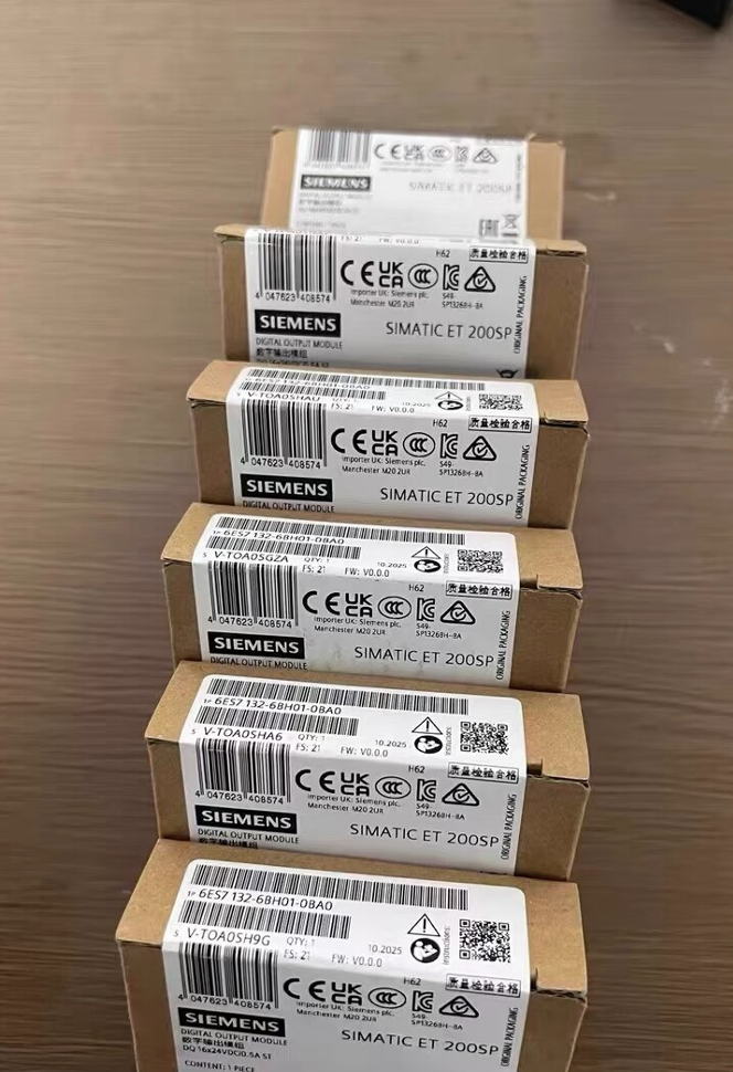

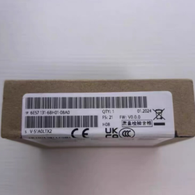
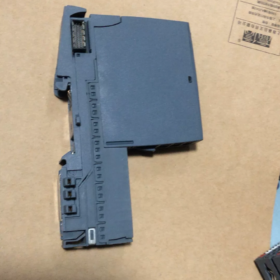
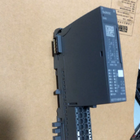
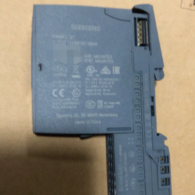
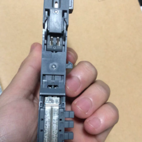
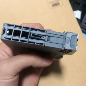
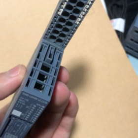
- تعيين النموذج الكامل & تحديد المواقع
SIMATIC ET200SP DI 16×24VDC ST Standard Digital Input Module of siemens
مسلسل: ET200SP Distributed I/O (PROFINET/PROFIBUS Remote Station)
وظيفة: 16-قناة 24 V DC digital input for collecting signals from PNP sensors such as switches, مفاتيح القرب, photoelectric sensors and limit switches
Coding Type: Mechanical Coding Type A, only compatible with Type A0 BaseUnit
انهيار رمز النموذج
| مقطع الكود | تعريف |
| 6ES7131 | ET200SP Digital Input (من) Module Series |
| 6BH01 | 16-قناة 24 V DC Standard DI, Hardware Version V1 |
| 0BA0 | Standard industrial version, no anti-corrosion coating and no surge suppression enhancement |
- المواصفات الكهربائية الأساسية
2.1 مزود الطاقة & خصائص الإدخال
Rated Supply: 24 في العاصمة, النطاق المسموح به 19.2 ~ 28.8 V, with reverse polarity protection
نوع الإدخال: P-reading (Sinking PNP Input, اللجنة الانتخابية المستقلة 61131 يكتب 3)
منطق 0: -30 V ~ +5 V
منطق 1: +11 V ~ +30 V
Typical On-state Current per Channel: 2.5 أماه; Maximum Total Module Current: 90 أماه
استهلاك الطاقة النموذجي: 1.7 دبليو
Channel Grouping: Two groups (Channels 0~7 / 8~15). All sensors within one group must be uniformly PNP or NPN; mixed wiring is prohibited.
2.2 Filter Delay (8 configurable levels in TIA Portal)
0.05 / 0.1 / 0.4 / 0.8 / 1.6 / 3.2 / 12.8 / 20 آنسة
Additional cable delay of 30 ~ 500 ميكروس. A filter setting ≥3.2 ms is recommended for environments with heavy interference from inverters.
2.3 Maximum Cable Length
Shielded Cable: 1000 m maximum
Unshielded Cable: 600 m maximum
- الهيكل الميكانيكي & تثبيت
- أبعاد: 15 مم (دبليو) × 73 مم (ح) × 58 مم (د), ultra-narrow compact design
- فئة الحماية: IP20, DIN rail mounting inside control cabinet only
- درجة الحرارة المحيطة
Horizontal Mounting: 0 ~ +60 درجة مئوية
Vertical Mounting: 0 ~ +40 درجة مئوية
تخزين & مواصلات: -25 ~ +70 درجة مئوية
- المؤشرات: Independent green LED for each channel (ON = Logic 1, OFF = Logic 0); no dedicated hardware fault LED
- Address Occupancy: Consumes 2 input bytes plus an additional 2 bytes for diagnostic QI information. Hardware interrupt, isochronous mode and counter functions are not supported.
- Wiring Diagrams (Type A0 BaseUnit Mandatory)
4.1 2-wire Passive Contacts (Limit Switches, Pushbuttons)
Wire directly to the A0 BaseUnit: one contact terminal connects to DIx, the other to M (24 V negative). For wire breakage detection, connect a 25 ~ 45 kΩ resistor in parallel with the contact.
4.2 3-wire PNP Sensors (Common Photoelectric / Proximity Switches)
Potential distribution terminal required:
Sensor Brown Wire: لام+ 24 V
Sensor Blue Wire: Common M Ground
Sensor Black Wire (إشارة): Connect to module DI channel
> NPN sensors must not be directly wired to this module; logic 1 signals cannot be detected.
4.3 2-wire Inductive Proximity Sensors
Maximum closed-circuit current limited to 1.5 أماه. Long cables may trigger false wire-breakage alarms.
- وظائف التشخيص & Functional Limitations
- Supports wire breakage diagnosis (parallel detection resistor required); short-circuit diagnosis unavailable
- No channel-level overcurrent protection; sensor short-circuits will not trigger individual channel fault alarms
- No encoder power supply output and no auxiliary 24 إمدادات العاصمة الخامس
- Supports I&M0 ~ I&M3 device information; hardware automatically recognized by TIA Portal
- توافق الاتصالات: S7-1200/1500 CPU, ET200SP CPU, بروفينت آيو, بروفيبوس موانئ دبي
- Comparison of Derivatives in the Same Series
| Model Number | الاختلافات | التطبيقات النموذجية |
| 6ES7131-6BH01-0BA0 | Standard basic DI without anti-corrosion coating | General workshops, standard equipment under normal temperature |
| 6AG1131-6BH01-7BA0 | SIPLUS anti-corrosion coating, نطاق التشغيل -40 ~ +70 درجة مئوية | Chemical plants, الموانئ, high-humidity corrosive environments |
| 6ES7131-6BH01-0CA0 | Built-in surge suppression | Long-distance field cables, lightning-prone areas |
| 6ES7131-6BH00-0BA0 | Obsolete older model, fully hardware compatible | Spare part replacement for legacy equipment |
- سيناريوهات التطبيق النموذجية
- Automotive Assembly Lines: Signal collection for fixture position confirmation, safety gates and workstation pushbuttons
- التعبئة والتغليف & Logistics Equipment: Photoelectric counting, jam detection switches, sorting trigger signals
- أنظمة معالجة المياه: Float level switches, valve limit switches, pump running feedback signals
- أتمتة الأدوات الآلية: Travel limit switches, tool detection, safety circuit contacts
- اختيار النموذج & احتياطات العملية
- Only Type A0 BaseUnit is permitted; Type B0/C0 and other coded base units are incompatible. The module features an integrated Type A coding lock to prevent incorrect insertion.
- All sensors within each 8-channel group must share the same polarity; PNP and NPN devices cannot be mixed in one group.
- Cables routed near inverters and servo drives must be shielded to eliminate false triggering.
- Increase input filter delay for long cables to suppress electromagnetic interference.
- No SIL safety certification. This module cannot be used independently for safety circuits; safety relays or safety I/O modules are required.
- Alternative Replacement Options
- Direct equivalent replacement: 6AG1131-6BH01-7BA0 (wide-temperature anti-corrosion version)
- Higher-density upgrade: 6ES7131-6BF01-0BA0 (8-channel isolated DI module)
- Safety application replacement: 6ES7131-6FD01-0BB1 (السلامة دي, سيل 2 متوافق)
Full Operating Principle of Channel Grouping for 6ES7131-6BH01-0BA0
- Hardware Group Definition (مُثَبَّت 8 Channels per Group, 2 Groups Total)
ال 16 input channels are physically divided into two independent reference potential domains with completely separated internal hardware circuits:
- مجموعة 1: Channels DI.0 ~ DI.7 (أولاً 8 نقاط)
- مجموعة 2: Channels DI.8 ~ DI.15 (Last 8 نقاط)
Core Underlying Logic: Independent Common Reference M per Group
The module assigns a separate M reference ground to each group internally, with no electrical connection between the two groups.
All channels within one group share the same group M potential. الجميع 8 channels in a single group must use identical sensor polarity (all PNP or all NPN); the two groups may adopt different polarities.
- Circuit Operation of Channel Groups
2.1 Standard Mode (افتراضي المصنع: بنب / Sinking P-reading)
Internal circuit structure for each group:
Each DIx channel is internally pulled up to 24 في العاصمة
Signal conduction condition: DIx connected to 0 V (م) → Circuit closed, PLC detects Logic 1
Compatible with 3-wire PNP sensors and 2-wire passive contacts (أزرار الضغط / مفاتيح الحد)
قواعد الأسلاك:
Negative terminals of all sensors in the group connect uniformly to the group M terminal
PNP and NPN sensors cannot coexist in one group; otherwise partial channels remain permanently Logic 0 or Logic 1.
2.2 Wiring NPN Sensors to a Single Group (Source Output)
NPN sensors output low-level 0 V signals which cannot be recognized by default. Modify the group common M connection to 24 V L+:
DIx receives high-level 24 V signal from NPN sensor to close the circuit
Only the target group’s common potential needs adjustment; the other group remains unaffected.
2.3 Key Isolation Features of Group Separation
No electrical linkage between the two groups. It is fully allowed to connect Group 1 M to 0 V and Group 2 M to 24 V L+.
Short-circuit or ground faults on one group will not interfere with signal acquisition on the other group.
Sensors on long cables or separate power supply loops can be grounded in separate groups to reduce ground loop interference.
- Mapping Between I/O Addresses and Channel Groups (PLC Memory Area)
ال 16 channels occupy 2 input bytes, strictly allocated by group in one-to-one correspondence:
مجموعة 1 (من.0~DI.7): `IBx` (1st byte, bit0 ~ bit7)
مجموعة 2 (DI.8~DI.15): `IBx+1` (2nd byte, bit0 ~ bit7)
مثال: Module start address IB100
DI0~DI7 = I100.0 ~ I100.7
DI8~DI15 = I101.0 ~ I101.7
Diagnostic QI status data is uploaded in two segments corresponding to each group.
- Terminal Layout of Type A0 BaseUnit Matching Channel Groups
Terminal arrangement logic of matching A0 BaseUnit:
- Terminals 1~8: من.0~DI.7 (مجموعة 1) + مجموعة 1 Common M
- Terminals 9~16: DI.8~DI.15 (مجموعة 2) + مجموعة 2 Common M
The base unit is equipped with two independent M terminals physically separated for connecting different potentials to each group.
- Three Typical Practical Wiring Scenarios for Grouping
سيناريو 1: All PNP Wiring (الأكثر شيوعًا)
مجموعة 1 M and Group 2 M shorted together to 0 V (24 V negative)
Uniform 3-wire PNP sensors and passive switches for both groups with no conflict
سيناريو 2: One Group PNP, One Group NPN (Permitted)
مجموعة 1 (DI0~7) M connected to 0 V → Wired with PNP photoelectric / proximity sensors
مجموعة 2 (DI8~15) M connected to 24 V L+ → Wired with NPN sensors
This configuration is valid. Independent group potentials do not interfere with each other, and all signals are recognized normally.
سيناريو 3: Mixed PNP & NPN Within One Group (Strictly Forbidden)
مثال: DI0~4 wired to PNP sensors, DI5~7 wired to NPN sensors
The group only has one shared M potential, creating circuit conflicts with the following phenomena:
Partial channels permanently no signal (constant Logic 0)
Random false triggering and signal flickering
Severe cases cause input circuit overload and permanent module channel damage
- Group-Based Diagnostic Functions
Wire breakage detection operates on a per-group basis:
Detection resistors are wired in parallel to all channels in one group; wire-break diagnosis is enabled/disabled for the entire group at once
A wire break fault detected in one group only triggers diagnostics for that group, leaving the other group unaffected
Filter delay parameters apply to the entire module; independent filter settings per group are unsupported.
- Engineering Advantages of Dual-Group Design
- Dual-sensor compatibility: Direct wiring for PNP and NPN sensors without intermediate relays
- Isolation of different potential loops: Separate high-power and low-power machine tool signals into two groups to mitigate common-mode interference
- Fault zoning: Short-circuit or ground faults on one group will not disable all 16 القنوات
- Flexible cabling: Each group can be powered by an independent 24 إمدادات العاصمة الخامس; power faults on one supply do not impact the other group.
- Quick Summary
- Hardware fixed into 2 groups of 8 قنوات لكل منهما, with an independent common reference M for every group
- All sensors within one group must share identical polarity; the two groups may use different polarities freely
- Address allocation, diagnostic data and common reference potentials are managed separately by group
- Core essence: The two groups feature electrically isolated input circuits and share only the module power supply.





NH42-63-318x560.png "مفاتيح النقل التلقائي من نوع الكمبيوتر الشخصي CHINT (المنشطات الأمفيتامينية)NH42-63/4SZ")



