 Schütz,Leistungsschalter,Sensor,Encoder,SPS,Konverter

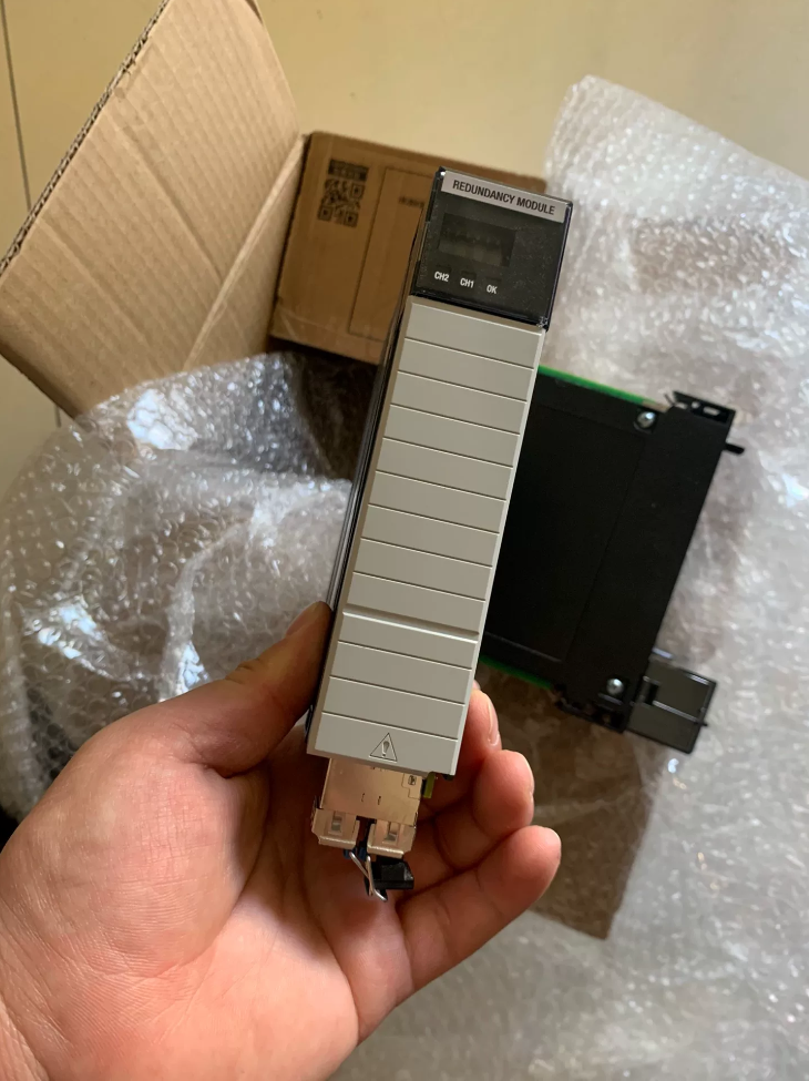

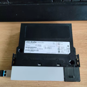
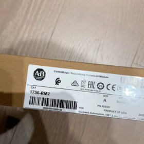
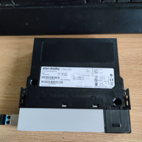

Grundlegende Informationen
Vollständiger Name: 1756‑RM2 ControlLogix Enhanced Redundancy Module
Marke: Allen-Bradley (Rockwell Automation)
Plattform: ControlLogix 1756 Chassis Series
Positionierung: Enhanced controller redundancy synchronization module for building ControlLogix controller-level hot-standby redundancy systems
Lebenszyklus: Active Mature (mature phase, normal supply, serviceable)
Kernfunktion
Must be used in pairs (1 module in primary chassis + 1 module in secondary chassis), accomplishing the following via fiber-optic link:
- High-speed real-time synchronization of primary/secondary controller programs, tags, task states, and I/O data
- Monitoring of primary controller operational health status
- Bumpless automatic switchover upon fault trigger (typical switchover time < 100 MS)
⚠️ Cannot operate as a single module; must not be mixed with the older 1756‑RM — both chassis must use RM2.
Wichtige technische Spezifikationen
| Parameter | Spezifikation |
| Backplane Power | 1.16 A @ 5.1 In DC; 3.4 mA @ 24 In DC |
| Maximum Power Consumption | 6 W |
| Synchronization Bandwidth | 1 Gbit/s (Gigabit fiber link) |
| Fiber Interface | Dual SFP fiber channels (Channel A/B, link redundancy) |
| Compatible Fiber Cables | 1756‑RMC1 (1 M), 1756‑RMC3 (3 M), 1756‑RMC10 (10 M) |
| Standardbetriebstemperatur | -20 °C ~ +70 °C |
| Gewicht | ≈ 0.3 kg |
| Sicherheitszertifizierung | Supports SIL2 application scenarios |
Modellvarianten
- 1756‑RM2 (Standard): For indoor use in conventional control cabinets
- 1756‑RM2XT (Extended Temperature): -40 °C ~ +70 °C, for outdoor/non-air-conditioned cabinets; must be used with XT series chassis
Pairing rule: RM2 ↔ RM2; RM2XT ↔ RM2XT; cross-mixing is not allowed
Compatible Controller List
Supports only ControlLogix 5560 / 5570 Serie:
1756‑L71, L72, L73, L74, L75
1756‑L61, L62, L63
Minimum firmware version requirements apply; refer to the official redundancy manual. 5580 (L8x) does not use 1756‑RM2; use 1756‑RM3 instead.
1756‑RM2 vs. Legacy 1756‑RM
| Artikel | 1756‑RM2 (Enhanced Redundancy) | 1756‑RM (Traditional Redundancy) |
| Sync Speed | 1000 Mbit/s | 100 Mbit/s |
| Data Sync Capability | Supports larger tag volumes, faster scan cycles | Struggles with large data volume synchronization |
| Fiber Link | Dual redundant fiber | Single link |
| Mischen | Cannot be paired with RM | Cannot be paired with RM2 |
| Empfohlen für neue Projekte | ✅ Bevorzugt | ❌ Legacy system maintenance only |
Minimum Redundancy Configuration – Hardware Architecture
2 × 1756‑RM2
2 redundant controllers of the same model and firmware
2 sets of 1756 chassis, 2 Netzteile
All communication modules in primary and secondary chassis must be paired one-to-one (same model, same firmware)
One pair of 1756‑RMCxx fiber cables connecting the two RM2 modules
Installation Mandatory Specifications
- Both RM2 modules must be installed in the exact same slot number in both chassis;
- The fiber link directly connects the two RM2 modules — no switches in between;
- All module models and firmware versions in both primary and secondary chassis must be strictly identical;
- Minimum fiber bend radius ≥ 30 mm; unused SFP ports must be fitted with dust caps.
Softwarekonfiguration
Programmiersoftware: Studio 5000 Logix Designer
Companion Tool: RMCT (Redundancy Module Configuration Tool)
Redundancy Mode: Enhanced Redundancy
Typical Application Industries
Thermal/hydropower, Petrochemie, Wasseraufbereitung, Schienenverkehr, groß angelegte Produktionslinien, DCS control — continuous processes that cannot tolerate downtime.
Definitionen der LED-Anzeigen (Module Front Panel)
OK: Module power and backplane are normal
CHA / CHB: Status of the two fiber-optic links
SYNC: Primary/secondary synchronization status
Common Troubleshooting Points
- SYNC LED off: Fiber break, dirty connectors, mismatched module models at both ends, inconsistent slot positions;
- Frequent switchovers: Inconsistent firmware versions, insufficient backplane power, excessive fiber attenuation;
- Cannot enter Qualify state: Incompatible modules present in the chassis.
1756-RM3 Complete Replacement Relationship & Kompatibilitätshinweise (vs. 1756-RM2, Focus on L8 Controllers)
- Core Hard Compatibility Red Lines (Officially Mandatory Rules)
Cross-model pairing is NOT allowed!
- 1756-RM2 / RM2XT
✅ Supports: 5570 (L7x) Controller
❌ Officially not recommended for new projects with L8x (5580); existing L8+RM2 is a transitional compatibility solution and does not receive new feature support
❌ Absolutely cannot pair with RM3 (one RM2 + one RM3 cannot establish redundancy synchronization)
- 1756-RM3 / 1756-RM3XT (Extended Temperature Model)
✅ Native support: 5580 (L8xEP), 5570 (L7x), 5590 next-generation controllers
✅ Officially designated standard module for L8 series redundancy systems
❌ Cannot be paired with RM2/RM2XT
Pairing iron rule:
RM2 ↔ RM2; RM2XT ↔ RM2XT
RM3 ↔ RM3; RM3XT ↔ RM3XT
Cross-pairing is strictly prohibited
- Generation Replacement Roadmap
Weg 1: New Project Selection (Bevorzugt)
L7x (5570) neue Projekte: Choose either 1756-RM2 or 1756-RM3
L8x (5580) neue Projekte: Mandatory selection of 1756-RM3; RM2 is no longer recommended
Rockwell long-term product strategy: RM3 is the next-generation upgrade replacement for RM2; future new features will only be iterated on RM3
Weg 2: Existing System Upgrade Migration
Scenario A: Existing L7x + 1756-RM2 System
Cannot directly perform online single-module replacement upgrade
Choose one of two options:
- Shut down and replace both RM2 modules → replace as a pair with 1756-RM3; chassis and CPU can remain L7x; re-download redundancy configuration
- Continue running with RM2, only procure RM2 as spare parts (Notiz: mature phase of lifecycle)
Scenario B: Controller Upgrade Migration from L7x to L8x
⚠️ Wichtig: L8 controllers cannot directly carry over existing RM2 modules (high engineering risk)
Standard migration solution:
L7 + RM2 → Full system retrofit: Replace controller with L8x + replace redundancy modules as a pair with 1756-RM3
III. Hauptunterschiede: 1756-RM3 vs. 1756-RM2 (Auswahlbasis)
| Vergleichsartikel | 1756-RM2 | 1756-RM3 |
| Fiber Interface | Fixed integrated optical module, dedicated cable 1756-RMCxx required | Hot-swappable SFP module (LC interface), flexible selection of multimode/singlemode SFP |
| Maximum Fiber Distance | Factory cable max 10 M | Bis zu 70 km with long-reach SFP, suitable for long-distance separated chassis |
| Kompatible CPU | L6x, L7x; L8 compatible (Übergang) | Full compatibility with L7x, L8x (5580), 5590; native optimization for L8 |
| Diagnostic Capability | Basic alarms | Built-in microSD card fault log recording, refined link diagnostics, fiber optical power monitoring |
| Redundancy Sync Bandwidth | 1 Gbit/s | 1 Gbit/s, optimized for L8 large-tag sync efficiency |
| Minimum Software Version | Studio 5000 V28+ | Studio 5000 V33.00 and above |
| XT Extended Temperature Version | 1756-RM2XT | 1756-RM3XT (-25 ~ +70 °C) |
| Fiber Cable | Must purchase dedicated 1756-RMC1/RMC3/RMC10 | No dedicated cable required; standard LC fiber + matching SFP |
- Mandatory Configuration List for L8 (5580) Controller Redundancy System (using RM3)
- Pair: 2 × 1756-RM3 (or paired RM3XT)
- CPU: Same model L8xxEP / L8xxEPXT (primary and secondary fully identical)
- Chassis: Same model for primary and secondary; RM3 installed in exactly the same slot number
- Kommunikationsmodule: Modules in both chassis paired one-to-one, unified firmware versions
- SFP modules: Both RM3 modules must use the same SFP model; fiber direct connection, no switch relay allowed
- Software: Studio 5000 ≥ V33
- Clarification of Common Engineering Misconceptions
- ❌ Missverständnis: “I have an existing L8 controller, just buy RM2 and it will work”
✅ Fakt: It can run at the hardware level, but it is a transitional compatibility solution; new RM3 diagnostics and long-distance fiber features are unavailable; officially not recommended for new projects; compatibility risks exist with future firmware upgrades.
- ❌ Missverständnis: One RM2 and one RM3 can form a pair for redundancy
✅ Fakt: Completely unable to synchronize; system cannot enter Qualify ready state; do not attempt
- ❌ Missverständnis: RM3 can directly use existing RM2 fiber cables 1756-RMC
✅ Fakt: Interface is incompatible! RM3 uses standard SFP LC interface and cannot use RM2-dedicated RMC series cables.
- Spare Parts Procurement Recommendations
- New L8 redundancy projects: Procure 1756-RM3 directly (choose RM3XT for extended temperature environments)
- Existing L7 + RM2 systems: Continue procuring RM2 as spares; plan a one-time paired upgrade to RM3 during retrofit planning
- Long-term planning: Prioritize RM3 for all new redundancy systems; RM2 gradually positioned as legacy maintenance spare parts
Allen‑Bradley 1756‑RM3 Complete Detailed Technical Specifications
Grundlegende Informationen
Modell: 1756-RM3 (Standard) / 1756-RM3XT (Extended Temperature XT Edition)
Vollständiger Name: ControlLogix Premium Redundancy Module
Plattform: ControlLogix 1756 Chassis
Positionierung: Officially standard redundancy module for 5580 (L8xEP) Controller; backward compatible with L7x (5570) Controller
Mandatory Pairing Rule: Used in pairs; RM3 ↔ RM3; RM3XT ↔ RM3XT; strictly prohibited to mix-pair with RM2/RM2XT
- Elektrische Parameter (Backplane Power)
| Parameter | 1756-RM3 / 1756-RM3XT |
| 5.1 V DC Backplane Current | 1.18 A |
| 24 V DC Backplane Current | 3.4 mA |
| Maximum Power Consumption | ≈ 6.2 W |
| Module Slot | Single-slot module, besetzt 1 slot in 1756 chassis |
| Hot Swap | Supports chassis hot-swap (not recommended to remove individually during redundancy operation) |
- Fiber Communication Interface (Key Difference from RM2)
- Kanäle: Dual independent SFP slots (Link1 / Link2, link redundancy)
- Schnittstellentyp: Industrial standard SFP, LC duplex fiber interface
❗ Cannot use 1756‑RMCxx series RM2-dedicated cables
- Sync Speed: 1000 Mbit/s (Gigabit)
- Supported SFP (Officially Compatible)
Multimode SFP: Kurze Distanz (≤ 2 km), 850 nm
Singlemode SFP LX: 1310 nm, bis zu 10 km
Long-reach singlemode SFP: Bis zu 70 km (suitable for long-distance primary/secondary chassis separation scenarios)
- Topology Mandatory Requirement: Two RM3 modules directly connected via fiber; fiber must not pass through switches or optical transceivers as intermediaries
- Minimum Fiber Bend Radius: ≥ 30 mm
III. Compatible Controller List
✅ Native full support
1756-L81EP, L83EP, L85EP (5580 standard controllers)
1756-L81EPXT, L83EPXT, L85EPXT (XT extended temperature controllers)
1756-L71/L72/L73/L74/L75 (5570 L7 series)
✅ Compatible with GuardLogix L8x safety controllers
❌ Does not support L6x legacy controllers; does not support pairing with RM2 for redundancy
- Umweltspezifikationen
| Parameter | 1756-RM3 (Standard) | 1756-RM3XT (Extended Temperature) |
| Betriebstemperatur | 0 °C ~ +60 °C | -25 °C ~ +70 °C |
| Storage/Transport Temperature | -40 °C ~ +85 °C | -40 °C ~ +85 °C |
| Relative Luftfeuchtigkeit | 5% ~ 95%, nicht kondensierend | 5% ~ 95%, nicht kondensierend |
| Schutzklasse | IP20 (Nur Schrankeinbau) | IP20 |
| Vibration IEC 60068-2-6 | 2G, 10 ~ 500 Hz | 2G, 10 ~ 500 Hz |
| Schock (Betrieb) | 30G | 30G |
- Mechanical Dimensions and Weight
Formfaktor: Standard 1756 single-slot module
Abmessungen: 38.1 mm (W) × 152.4 mm (H) × 130 mm (D)
Nettogewicht: ≈ 0.30 kg
- HMI and LED Indicators
- 4-Digit Digital Display: Shows module status, Fehlercodes, link information
- LED Indicators
OK: Stromversorgung des Moduls, backplane communication normal
LINK1 / LINK2: Status of the two SFP fiber links
NET: Redundancy synchronization network status
MOD: Redundancy role / synchronization status
MOD solid on = primary controller; blinking = standby; fast blinking = sync abnormal / not ready
VII. Software and Firmware Requirements
Programmiersoftware: Studio 5000 Logix Designer V33.00 and above
Companion Tool: Redundancy Module Configuration Tool (RMCT) integrated within Studio 5000
Redundancy Mode: Enhanced Redundancy
Typical fault switchover time: < 100 MS (depends on user program size)
VIII. Storage and Diagnostic Enhancements (RM3 Exclusive, Not Available on RM2)
- Built-in MicroSD card slot: Can record redundancy switchover logs, link faults, optical power anomaly events
- Real-time fiber optical power diagnostics, early warning of fiber attenuation and aging
- Refined synchronization timing diagnostics, locating tag synchronization bottlenecks
- Supports online link quality monitoring
- Industrial Certifications
UL Listed, c-UL-US, CSA, CE (EN61131-2, EN61326)
Klasse I Div. 2 hazardous area certification (matching corresponding XT systems)
- Key Parameter Comparison Summary: 1756-RM3 vs. 1756-RM2
| Artikel | 1756-RM2 | 1756-RM3 |
| Optical Interface | Integrated fixed optical module, dedicated 1756-RMC cable | Hot-swappable SFP LC universal fiber |
| Maximum Fiber Distance | Factory cable max 10 M | Bis zu 70 km via SFP |
| L8 Controller Compatibility | Transitional compatibility, not recommended for new projects | Native standard, full feature set |
| Diagnostic Logging | No SD card logging | Built-in SD card fault recording, optical power monitoring |
| Minimum Studio 5000 Version | V28 | V33 |
| Pairing Partner | RM2/RM2XT only | RM3/RM3XT only |
- Engineering Installation Mandatory Specifications
- Both RM3 modules in primary and secondary chassis must be installed in exactly the same slot number
- All module models and firmware versions in primary and secondary chassis must correspond one-to-one
- SFP module models must be consistent at both ends; unused SFP ports must be fitted with dust caps
- XT systems must be fully XT: RM3XT + XT chassis + XT controller; standard modules cannot be mixed in





NH42-63-318x560.png "Automatische Transferschalter vom Typ CHINT PC (ATS)NH42-63/4SZ")



