 Schütz,Leistungsschalter,Sensor,Encoder,SPS,Konverter

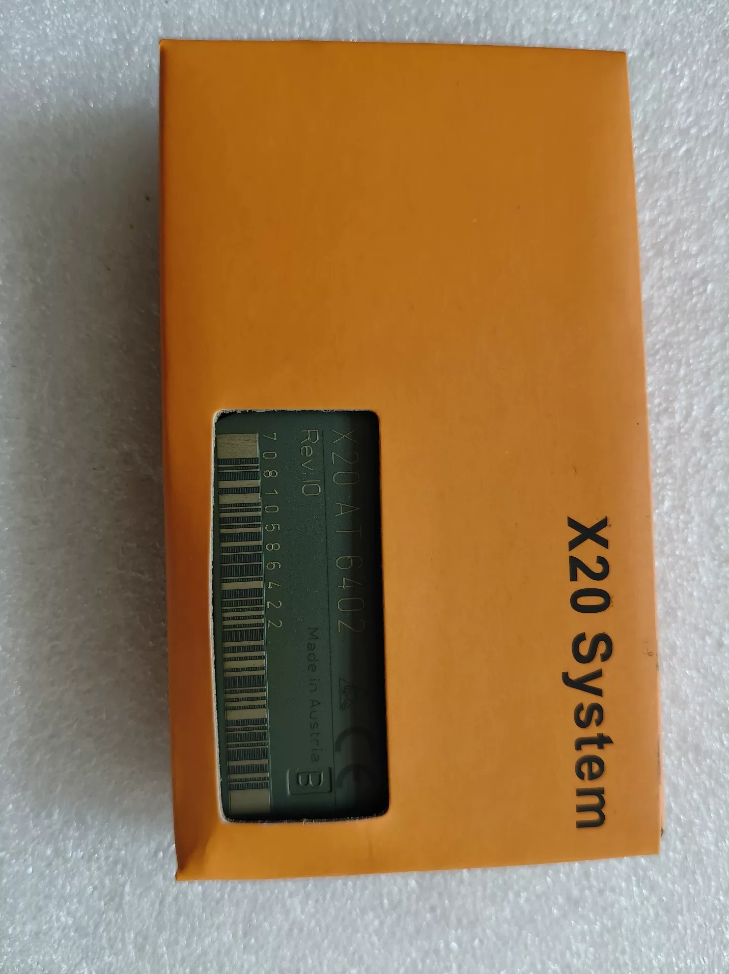

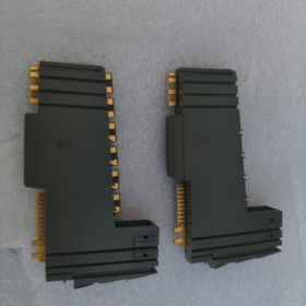
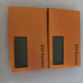
X20: X20 I/O-Systemserie
BEI: Analoge Temperatur Eingang
6402: 6Kanal-Thermoelementmodul; X20cAT6402 ist die konformbeschichtete Version (Kondensation & beständig gegen korrosive Gase)
Allgemeine Beschreibung
X20AT6402 ist ein 6-Kanal-Thermoelement-Temperaturerfassungsmodul für verteilte X20-SPS-E/A. Es verfügt über eine integrierte Klemmen-Kaltstellenkompensation, Unterstützung der Thermoelementtypen J/K/N/S/B/R. SigmaDelta 16bit ADC; Es kann technische Temperaturwerte oder rohe Millivolt-Messwerte ausgeben.
⚠️Hinweis: Keine galvanische Trennung zwischen den Kanälen; Es besteht eine Isolierung zwischen Busseite und E/A-Seite.
Obligatorisches Zubehör: X20TB12 (12Stiftklemmenblock), Busbasis X20BM11. Klemmen sind NICHT im Lieferumfang des Moduls enthalten.
Wichtige technische Spezifikationen
| Artikel | Spezifikation |
| Kanäle | 6 Thermoelement-Eingänge |
| Unterstützte Thermoelemente | J, K, N, S, B, R (EN60584) |
| ADC | Sigma-Delta, 16-bisschen |
| Kaltstellenkompensation | Integrierte terminalbasierte Vergütung; kein externer PT1000 erforderlich |
| Filterzeit | Konfigurierbar: 1 ms ~ 66,7 ms |
| Eingabebereich | ±70mV (mV-Signal des Thermoelements) |
| Auflösung | 0.1 ℃ / 0.01 ℃ per Software wählbar; Rohwert:1.0625 μV |
| Grundgenauigkeit bei 25℃ | J: ±0,10 %; K/N: ±0,11 %; S: ±0,17 % |
| Gleichtaktspannung | ±15V |
| Stromverbrauch | Bus: 0.01 W; I/O-Seite: 0.91 W |
| Betriebstemperatur | Horizontale Montage:0-55℃; Vertikale Montage:0-50℃; Leistungsreduzierung um 0,5℃/100m über 2000m Höhe |
| Schutzklasse | IP20, Nur für Schrankmontage |
| Lagertemperatur | -40 ~ +85℃ |
| Diagnose | Modulstatus, Kanaldrahtbrucherkennung, LED-Statusanzeigen |
| Ausgabeformat | INT; technische Temperatur oder rohe mV-Werte wählbar |
Hinweise zur Verkabelung
- Jeder Thermoelementkanal verwendet 2 Terminals (TC+, TC). Sechs Kanäle belegen 12 Stifte, Passender Klemmenblock X20TB12.
- Vertauschen Sie die Polarität des Thermoelements nicht; Verwenden Sie immer passende Thermoelement-Verlängerungskabel.
- Keine galvanische Trennung zwischen den Kanälen. Für Mehrpunktmessung, Kontrollieren Sie die Referenzpotentialdifferenz, um Gleichtaktstörungen zu vermeiden.
- Die Kaltstellenkompensation nutzt die integrierte Temperaturmessung an den Anschlüssen; Halten Sie den Klemmenblock von wärmeerzeugenden Bauteilen fern.
Softwarekonfiguration (Automatisierungsstudio)
- Fügen Sie die Hardware „X20AT6402“ im Hardwarebaum hinzu.
- Unabhängig einstellbarer Sensortyp (J/K/N/S/B/R) für jeden Kanal.
- Filterzeit konfigurieren; Ausgang auswählen: technische Temperatur ℃ oder roher Millivoltwert.
- Drahtbruchdiagnose aktivieren.
Alternative Auswahl der X20Serie
| Modell | Kanäle | Merkmale |
| X20AT2402 | 2 | Kostengünstiges 2-Kanal-Thermoelementmodul, gleiche Sensorunterstützung |
| X20ATA492 | 2 | Galvanische Kanal-zu-Kanal-Trennung, erfordert einen externen PT1000-Vergleichsstellensensor an den Klemmen |
| X20cAT6402 | 6 | Schutzbeschichtet; für hohe Luftfeuchtigkeit / Umgebungen mit korrosiven Gasen |
Typische Anwendung
Wärmebehandlungsöfen, Öfen, Spritzgießmaschinen, Extruder, Öfen, Mehrpunkt-Temperaturerfassung für energiebezogene Geräte.
Checkliste für die Inspektion gebrauchter Module
- Visuelle Kontrolle: Keine terminalen Brandspuren; Die Goldkontakte der Rückwandplatine sind intakt.
- Poweron-Test: RUN-LED normal; Keine Modulfehleralarme.
- Funktionstest: Schließen Sie ein bekanntes Thermoelement vom Typ K an; Vergleichen Sie die Messwerte über alle Kanäle hinweg mit dem Referenzthermometer.
- Überprüfen Sie die Hardware-Revision; Unterscheiden Sie zwischen der Standardversion und der konformbeschichteten „C“-Variante.
B&R X20AT6402 Installationshandbuch (Praktische englische Version)
Offizielles vollständiges Dokument: X20-System-Benutzerhandbuch, Kapitel 9.32.7 für X20AT6402. Download von B&R offizielle Website nach dem Login. X20cAT6402 verfügt über identische Hardware-Mechaniken mit aufgebrachter Schutzbeschichtung.
Dies ist Slicestyle X20 I/O. Pflichtteile: Busbasis X20BM11 + Federklemmenblock X20TB12; Klemmen sind nicht im Modul enthalten.
1 Sicherheitsvoraussetzungen
- Nur im Schaltschrank installieren; Schutzart IP20. Nicht für den Einsatz im Freien geeignet.
- Trennen Sie für die Installation die 24-V-Gleichstromversorgung / Entfernung / Verdrahtung. Hotswap wird unterstützt, Führen Sie die Verkabelung jedoch bei ausgeschalteter Stromversorgung durch.
- ESD-Schutz: Tragen Sie ein antistatisches Armband. Berühren Sie die vergoldeten Backplane-Kontakte nicht direkt mit der Hand.
- Umgebungsbedingungen
| Artikel | Parameter |
| Betriebstemperatur (horizontale Montage) | 0~+55℃ |
| Betriebstemperatur (vertikale Montage) | 0~+50℃ |
| Höhe | 0-2000m uneingeschränkt; >2000 M, Reduzieren Sie die Umgebungstemperatur um 0,5℃ pro 100 m Höhe |
| Relative Luftfeuchtigkeit | 5-95 %, nicht kondensierend |
| Lagerung / Transporttemperatur | -40~+85℃ |
2 Mechanische Installation (DIN-Schiene TS35 EN60715)
2.1 Obligatorische Freigabe zur Wärmeableitung
Mindestens 10 mm Abstand links und rechts von jedem Modul.
Horizontale Montage: ≥35 mm freier Belüftungsraum über und unter dem Modul.
Vertikale Montage: Die CPU muss unter allen E/A-Modulen platziert werden.
Der Neigungswinkel darf 120° nicht überschreiten.
2.2 Montageverfahren
- Klemmen Sie den Bussockel X20BM11 auf die DIN-Schiene, Drücken Sie es nach unten, um es fest zu verriegeln.
- Schnappen Sie die X20-SliceI/O-Module nacheinander auf die Basis, Halten Sie die Module dicht nebeneinander.
- Setzen Sie X20AT6402 nach unten in den X20BM11-Sockel ein, bis ein hörbares Klicken zu hören ist; Vergewissern Sie sich, dass beide seitlichen Riegel vollständig eingerastet sind.
- X20TB12 montieren (12Stiftfederklemmenblock) auf die Vorderseite des Moduls aufstecken. Zur Offline-Vorverdrahtung können die Klemmen abgenommen werden.
Entfernungsverfahren
- Netzteil entfernen.
- Drücken Sie auf den dreieckigen Entriegelungsriegel oben am Modul; Heben Sie das Modul nach oben, um es von der Busbasis zu trennen.
- Ziehen Sie den Klemmenblock gerade nach außen.
2.3 Obligatorische Hardware-BillofMaterials
| Teile-Nr. | Beschreibung | Zweck |
| X20AT6402 | 6-Kanal-Thermoelement-Eingangsmodul | Signalerfassungseinheit |
| X20BM11 | Bushaltestelle | DIN-Schienenmontage, Rückwandbus, 24 V-Stromverteilung |
| X20TB12 | 12-Pin-Federklemmenblock | Feldverkabelung für Thermoelemente |
3 Elektrische Verkabelung
3.1 Bus-Stromversorgung
X20BM11 erhält 24 VDC zur Versorgung des Rückwandbusses und des Moduls X20AT6402.
Stromverbrauch: Busseite 0,01 W; E/A-Seite 0,91 W.
3.2 Feldverkabelung für Thermoelemente (X20TB12-Klemmen)
Sechs Thermoelementkanäle, Jeder Kanal verwendet TCx+, TCx-Differentialpaar; gesamt 12 Stifte.
Verwenden Sie immer ein passendes Thermoelement-Verlängerungskabel; Achten Sie unbedingt auf die Polarität.
⚠️Kritisch: Keine Isolierung zwischen den Kanälen; BustoI/O-Isolation vorhanden. Halten Sie die Gleichtaktspannung auf ≤ ±15 V, um Messwertdrift bei Multisensorsystemen zu verhindern.
Kaltstellenkompensation: Onboard-Terminaltemperaturmessung. Platzieren Sie den Klemmenblock entfernt von den Schützen, Netzteile und andere wärmeerzeugende Geräte.
Verkabelungspraxis: Verlegen Sie die Low-Level-mV-Signalkabel des Thermoelements getrennt von den Stromkabeln; Vermeiden Sie parallele Bündelungen. Einseitige Erdung des Kabels abschirmen: Schließen Sie die Abschirmung an die Schrankerde an; Lassen Sie die sensorseitige Abschirmung frei.
Verkabelung mit Federklemmen: Leiterquerschnitt 0,081,5 mm². Drücken Sie die Federlasche mit einem Schlitzschraubendreher, Draht einführen, Entriegelung zum Sperren des Leiters.
Empfohlene Praxis: Verbinden Sie die negativen Anschlüsse des Thermoelements mit der Modulreferenzmasse, um durch Welligkeit verursachte Messfehler zu unterdrücken.
3.3 Anschlussbelegung
| Kanal | Positiv | Negativ |
| TC1 | 1 | 2 |
| TC2 | 3 | 4 |
| TC3 | 5 | 6 |
| TC4 | 7 | 8 |
| TC5 | 9 | 10 |
| TC6 | 11 | 12 |
4 LED-Statusanzeigen
Definition der LEDs auf der Vorderseite des Moduls:
- LAUFEN Grün: Steadyon = Modul läuft einwandfrei; blinkend = keine gültige Konfiguration; aus = kein Strom / Hardwarefehler.
- ERR Rot: Ein = Modulfehler; blinkend = Kanaldrahtbruch / Sensorfehler.
Drahtbrucherkennung: Diagnose in der Software aktiviert; Die ERR-LED blinkt bei offenem Thermoelement-Stromkreis, SPS empfängt Fehlercode.
5 Hardwarekonfiguration für Automation Studio
- Fügen Sie die Hardware „X20AT6402“ in den Hardwarebaum ein; Überprüfen Sie die Firmware-Kompatibilität.
- Parameter pro Kanal:
Sensortyp: J / K / N / S / B / R
Filterzeit:1 ms ~ 66,7 ms; zur Unterdrückung von Netzrauschen bei 50 Hz auf 66,7 ms eingestellt.
Ausgabemodus: Technische Temperatur ℃ / roher mV-Wert.
Auflösung:0.1℃ /0,01℃ wählbar.
Drahtbruchdiagnose aktivieren.
- Laden Sie die Hardwarekonfiguration herunter, Starten Sie den X20-I/O-Bus neu.
- Validierung: Bekanntes Thermoelement anschließen; Vergleichen Sie die Temperaturwerte mit dem Referenzthermometer.
6 Inbetriebnahme & Fehlerbehebung
| Symptom | Anleitung zur Fehlerbehebung |
| Rote ERR-LED leuchtet dauerhaft | 24V-Versorgung prüfen; Überprüfen Sie das Einrasten der X20BM11-Verriegelung; Überprüfen Sie die Firmware-Version; Hardwareschäden |
| Temperaturwerte instabil / Bammel | Umgekehrte Polarität des Verlängerungskabels; gemischte Verlegung mit Stromkabeln; Gleichtaktspannung >±15V; schlechter Anschlusskontakt; Filterzeit zu kurz |
| -273℃ Messwert für alle Kanäle | Die Diagnose meldet einen offenen Stromkreis; Überprüfen Sie die Thermoelementkabel und den Sitz der Klemmenblöcke |
| Anomalie auf einem Kanal | Überprüfen +/- Polarität; Beschädigung des Thermoelementsensors; lockerer Anschlusscrimp |
7 Wartung & Ersatzteilaustausch
- Hotswap-Fähigkeit: Poweroff-Swap wird bevorzugt; Live-Modulaustausch erlaubt. Beim Ersetzen durch eine identische Teilenummer ist kein erneuter Projekt-Download erforderlich.
- Kabinettumgebung: Halten Sie den Schrank staubfrei, Kondenswasserbildung vermeiden.
- Unterscheiden Sie zwischen Standard-X20AT6402 und beschichtetem X20cAT6402; Ersatzteile können nicht beliebig ausgetauscht werden.
8 Offizieller Dokumentenzugriff
- B&Offizielle R-Website → Support → Dokument-Download, Suchen Sie nach der Teilenummer „X20AT6402“.;
- Verfügbare Dokumente: Datenblatt, X20-System-Benutzerhandbuch. B&Für den PDF-Download ist eine R-Benutzeranmeldung erforderlich.
X20AT6402 Fehlercode-Referenz & Beispiel für die ST-Variablenzuordnung
1 Kanaldiagnosestatus (2 Statusbits pro Kanal)
Jeder Thermoelementkanal kehrt zurück: Temperaturwert + Kanalstatusbits
| 2‑Bit-Kanalstatus | Beschreibung | Fehlerwert (0.1℃ INT-Modus) | Empfohlene Aktion |
| 0 | Normale Messung | Tatsächlicher Temperaturwert | Keine Aktion erforderlich |
| 1 | Eingang unter Bereich (unterhalb der Messspanne) | -32767 (0x8001) | Überprüfen Sie die Einstellung des Thermoelementtyps; Eingangs-Millivoltpegel zu niedrig |
| 10 | Eingangsbereichsüberschreitung (oberhalb der Messspanne) | +32767 (0x7FFF) | Thermoelement überschreitet Messbereich; Überprüfen Sie die Sensorauswahl erneut |
| 11 | Offener Stromkreis / Drahtbruch | +32767 (0x7FFF) | Defektes Thermoelement / Verlängerungskabel; lose Klemmenverbindung |
Globales Modulfehlerflag: „0x8000“ = allgemeiner Modulfehler
LED-Diagnosetabelle
| LED | Farbe | Zustand | Fehlerbeschreibung |
| R(Laufen) | Grün | Aus | Keine 24-V-Versorgung zum Modul |
| R(Laufen) | Grün | Dauerlicht | Normaler RUN-Zustand |
| R(Laufen) | Grün | Blinkt | Hardwarekonfiguration wurde nicht heruntergeladen, Pre-Operational-Modus |
| E(Fehler) | Rot | Aus | Kein Fehler vorhanden |
| E(Fehler) | Rot | Dauerlicht | Hardwarefehler / Nichtübereinstimmung der Firmware |
| E(Fehler) | Rot | Blinkt | Mindestens ein Kanal: Drahtbruch / Bereichsüberschreitung / Unterbereich |
| CH1-CH6-Kanal-LED | Grün | Dauerlicht | Kanalmessung fehlerfrei |
| CH1-CH6-Kanal-LED | Grün | Blinkt | Kanal offener Stromkreis / Bereichsverletzungsalarm |
2 ST StructuredText-Variablenzuordnung (Automatisierungsstudio)
X20AT6402 hat 6 Kanäle. Jeder Kanal liefert einen INT-Temperaturwert + Kanalstatusbyte.
Zwei Auflösungsmodi verfügbar: 0.1 ℃ (INT), 0.01 ℃ (DINT).
3 Umfassende Liste zur Fehlerbehebung vor Ort
- Alle Kanäle gelesen 32767
Symptom: Alle Kanäle geben „0x7FFF“ zurück, Kanalstatus =3 (Leerlauf).
Checkliste: X20TB12 vollständig eingesetzt; X20BM11-Verriegelungen verriegelt; 24 V Versorgungsspannungsabfall.
- Singlechannel-Retouren 32767, andere Kanäle normal
Mögliche Ursachen: Defektes Thermoelement / Verlängerungskabel; lockerer Anschlusscrimp; umgekehrte Polarität des Thermoelements.
- Jitter bei der Temperaturmessung / Drift
1) Filterzeit zu kurz und Netzstörung vorhanden; Stellen Sie die Filterzeit für die 50-Hz-Unterdrückung auf 66,7 ms ein.
2) Das Thermoelement-Verlängerungskabel verläuft parallel zu den Stromkabeln; separate Kabelführung; Einseitige Schirmerdung am Schrank.
3) Gleichtaktspannung zwischen den Kanälen >±15V. Keine Isolierung zwischen den Kanälen; große Referenzpotentialdifferenz zwischen mehreren Thermoelementen.
- ERR-LED leuchtet dauerhaft rot, RUN-LED blinkt grün
Nichtübereinstimmung der Firmware-Version; Die Hardwarekonfiguration stimmt nicht mit der physischen Hardware überein. Unterscheiden Sie zwischen X20AT6402 und X20cAT6402, Führen Sie keine Crosskompilierung der Konfiguration durch.
- 273℃-Anzeige behoben
Typisches Leerlaufsymptom bei aktivierter Drahtbruchdiagnose; Überprüfen Sie zuerst die Sensorverdrahtungsschleife.
4 Tipp zum Diagnosefunktionsblock
Die Standardbibliothek von Automation Studio stellt „X20DiagGetChannelState“ bereit()` Funktionsblock. Es liest den Kanalfehlerstatus direkt ohne manuelles Parsen der Bitmaske.
Geben Sie die Hardware-ID für X20AT6402 ein: „161BA9“.; Die Funktion gibt den aufgezählten Kanalfehlerstatus zurück.





NH42-63-318x560.png "Automatische Transferschalter vom Typ CHINT PC (ATS)NH42-63/4SZ")



