 Schütz,Leistungsschalter,Sensor,Encoder,SPS,Konverter

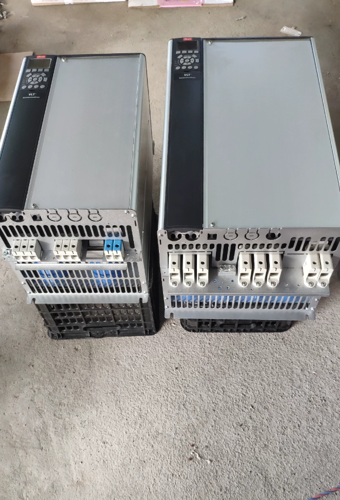

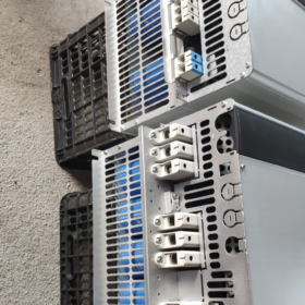
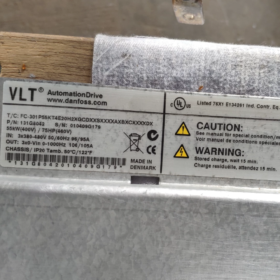
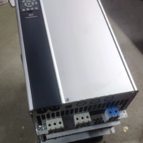
VLT AutomationDrive FC-302 Hochleistungs-Allzweckgerät Frequenzumrichter
Bestell-Nr.: 131F7151
Modellsegmentweise Dekodierung
FC-302 P55K T5 E20 H2 B G XXXX SXXXX AXBXCXXXXDX
| Feld | Bedeutung | Beschreibung |
| FC-302 | Produktserie | VLT AutomationDrive FC-302, mit Bewegungssteuerung, Sicherer Stopp, unterstützt Servoanwendungen |
| P55K | Nennleistung | 55 kW / 75 PS |
| T5 | Spezifikation des Netzteils | 3-Phase 380-500 V AC |
| E20 | Schutz vor Eindringen | Offener IP20-Rahmen, Schrankmontage |
| H2 | RFI-Filter | Industrieller EMV-Filter der Klasse C3 (2und Umgebung, Verwendung in Fabrikhallen) |
| B | Bremschopper | Eingebauter Brems-Chopper, Bremswiderstand anschließbar |
| G | Bedienfeld | LCP102 grafisches chinesisches Panel (Anzeige & Tastenfeld) |
| XXXX | PCB-Beschichtung / Energieoption | X = Standard unbeschichtete Leiterplatte, Keine zusätzlichen Stromversorgungsoptionen |
| SXXXX | Software-Revision | Neueste Werksstandard-Firmware-Version |
| AXT | Optionssteckplatz A | Keine A-Slot-Kommunikationskarte (Steckplatz A leer; Profinet, EtherNet-IP usw. nachrüstbar) |
| BX | Optionssteckplatz B | Keine B-Steckplatz-Erweiterungskarte |
| CX | Optionssteckplatz C | Keine C-Slot-MCO-Motion-Control-Karte |
| DX | Optionssteckplatz D | Keine D-Steckplatz-Optionskarte |
Grundlegende elektrische Spezifikationen
Nennleistung: 55 kW
Eingang: 3-Phase 380-500V AC
Kontinuierlicher Ausgangsstrom: 106 A
Überlast: 160 % für 1 Min (Hochüberlastmodus)
Rahmengröße des Fahrgestells: C4
On-Board-Komponenten: Zwischenkreisdrossel, Bremschopper, RFI-Filter der Klasse C3
Standardprotokoll: Modbus-RTU; Es sind keine zusätzlichen Kommunikationskarten eingebaut
Sicherheitsfunktion: Safe-Stop-Hardware-Terminal
Umgebungstemperatur: Volle Leistung bei 40°C; Leistungsreduzierung oben bis max. 50°C
Zusammenfassung der Schlüsselkonfiguration
✅ 55 kW, 380-500 V, IP20 offener Rahmen
✅ Eingebauter Brems-Chopper, kompatibel mit Bremswiderstand
✅ Ausgestattet mit dem grafischen Bedienfeld LCP-102
✅ Industrieller EMV-Filter der Klasse C3, integrierte Zwischenkreisdrossel
❌ Kein Profinet / EtherNet-IP oder andere Feldbuskarten; Nachrüstbar über A/B-Slots
❌ Keine MCO-Bewegungssteuerungskarte
Typische Anwendungen
Fans, Pumps, Extruder, Förderer, Mischer, Werkzeugmaschinenspindeln. Unterstützt Closed-Loop-Vektor, Open-Loop- und Servo-Modus; Geeignet für Anwendungen mit regenerativer Bremsenergie.
Ersatzteil & Hinweise zum Austausch
- Wenn kein Brems-Chopper erforderlich ist: Ändere B in X; Die Bestellnummer kann abweichen.
- Für Profinet: Passformoption AL (MCA120); für EtherNet-IP: Passformoption AN (MCA121).
- Gleiche Nennleistung ohne Panel: Ersetze G durch X, Das Modell wird zu FC-302P55KT5E20H2BXXXXSXXXXAXBXCXXXXDX
FC-302P55KT5E20H2BGXXXXSXXXXAXBXCXXXXDX
55 kW / 380-500 V IP20, eingebauter Brems-Chopper, EMV-Filter der Klasse C3, LCP102 grafisches chinesisches Panel; keine Kommunikationskarte, Keine MCO-Motion-Control-Karte.
- Wichtige Hinweise zur Verkabelung (Ausschalten; Ermöglichen Sie dem DC-Bus eine Entladezeit von mindestens 20 Minuten)
Hauptstromkreis
| Terminal | Funktion | Bemerkungen |
| L1/L2/L3 | 3-Phase 380-500V Eingang | NICHT mit U/V/W-Motorklemmen vertauschen |
| U/V/W | Motorleistung | An 3-Phasen-Motor anschließen; abgeschirmtes Kabel empfohlen |
| BR+ / BR‑ | Bremswiderstand | Für eingebauten Brems-Chopper; Schließen Sie hier den Bremswiderstand an, NICHT an DC-Bus-Klemmen anschließen |
| +DC /‑DC | Zwischenkreisbus | Wird für Mehrfachantriebssysteme mit gemeinsamem DC-Bus verwendet; Für den Standardbetrieb nicht angeschlossen lassen |
| PE | Schutzerde | Zuverlässige Erdung zwingend erforderlich |
Vorschlag zur Kabeldimensionierung für 55 kW: Stromversorgungskabel ≥16mm²; Motorkabel ≥16mm²; Bremswiderstandskabel ≥10mm².
Steuerstromkreis-Pflichtanschlüsse (Fehler oder Antriebssperre bei Ignorierung)
- STO Safe-Torque-Off: kurzes Terminal 12 Zu 37. Ohne Kurzschluss, Der Wechselrichterausgang ist gesperrt. Für externe Sicherheitskreise, Sicherheitskontakte in Reihe verdrahten.
- Coast-to-Stop-Terminal 27 ist werkseitig aktiv: wenn kein Auslaufen bis zum Stopp erforderlich ist: Parameter einstellen 5-12 = 0 (keine Funktion). Um den Leerlauf bis zum Stillstand beizubehalten: kurz 12-27.
- Terminals 12/13: interner +24V-Ausgang (max. 200mA); Klemme 20 = gemeinsame Masse des Digitaleingangs.
- Analoge Eingänge: 53 (0-10 V-Spannung); 54 (4-20 mA). Hardware-DIP-Schalter wählen die Spannung aus / aktuellen Modus.
- Terminals 68/69: RS485 Modbus-RTU; 68 =A, 69 =B.
Beispiel einer terminalbasierten Start-Stopp-Logik
18 (AUS): Start (Parameter5-10=Start)
19 (AUS): Umkehren (Parameter5-11=Umgekehrt)
54: 4-20 mA-Frequenzreferenz
Relais 01-02-03: konfigurierbar für Run / Fehlersignalisierung.
Praktische Ratschläge: Zuerst ohne Motor einschalten und den I/O-Status prüfen. Zur Inbetriebnahme, Motorkupplung abkoppeln und bei niedriger Drehzahl testen.
- Verfahren zum Zurücksetzen auf die Werkseinstellungen
Methode1: Empfohlene Initialisierung (Behält Betriebsstunden und Kommunikationseinstellungen bei)
- Hauptmenü → 14-Sonderfunktionen → 14-22 Betriebsmodus
- Wählen 2 Initialisierung → OK drücken
- Trennen Sie die Hauptversorgung; Warten Sie, bis das Panel vollständig dunkel ist; Schalten Sie die Stromversorgung erneut ein
- A80 Die Informationsmeldung „Laufwerk initialisiert“ wird angezeigt (kein Fehler); drücken Sie Zurücksetzen.
Methode2: Vollständige harte Initialisierung (Alle Parameter gelöscht)
- Ausschalten; Warten Sie, bis das Panel erlischt.
- Status halten + Wiedergabemenü + OK-Tasten zusammen, Anschließend die Hauptversorgung einschalten.
- Halten Sie die Taste 5 Sekunden lang gedrückt und lassen Sie sie dann los. Beim Einschalten wird der vollständige Werksreset abgeschlossen.
Tipp zur Parametersicherung: 0-50 LCP-Kopie → auswählen 1 Kopieren Sie alle Parameter nach LCP. Das Panel kann Parameter zum Herunterladen auf identische Einheiten speichern. Kopieren Sie Parameter NICHT über verschiedene Leistungsstufen hinweg.
- Wichtige Inbetriebnahmeparameter (Einheit mit eingebautem Brems-Chopper)
| Parameter | Beschreibung | Empfohlene Einstellung |
| 1‑01 | Prinzip der Motorsteuerung | VVCplus / Flussvektor. Asynchronmotor: VVCplus; hohes Drehmoment bei niedriger Drehzahl: Wählen Sie „Flussvektor“. |
| 1-20~1-26 | Daten auf dem Motortypenschild | Geben Sie die Leistung auf dem Typenschild ein, Stromspannung, aktuell, Frequenz, Geschwindigkeit genau |
| 1-29 | AMA Motor Auto-Tune | Statisches AMA; mit entkoppelter mechanischer Belastung durchführen |
| 2-10 | Bremsfunktion | Integrierten Brems-Chopper aktivieren → 1 Aktivieren |
| 2-11 | Ohmscher Wert des Bremswiderstands | Geben Sie den tatsächlichen Widerstandswert für den thermischen Schutz ein |
| 2-12 | Nennleistung des Bremswiderstands | Nennleistung des Eingangswiderstands zur Aktivierung des thermischen Modellschutzes des Widerstands |
| 3-41/3-42 | Hoch-/Herunterfahrzeit | Verlängern Sie die Verzögerung für Lasten mit hoher Trägheit, um AL-16-Überspannung zu vermeiden |
| 5-10/5-11 | Digitale Eingangsfunktionen | Start-Stopp konfigurieren, Richtungsbefehle |
Warnung vor Brems-Chopper: Kurzgeschlossene oder unterdimensionierte niederohmige Widerstände zerstören den Brems-Chopper. Immer ausfüllen 2-11 & 2-12 zum Wärmeschutz.
- Checkliste für die Eingangskontrolle für gebrauchte FC-302-55kW (C4-Rahmen)
Sichtprüfung
- Leiterplatten: Überprüfen Sie, ob Wasser eindringt, Korrosion oder Brandflecken. Untersuchen Sie den Kühlluftweg und den Lüfter auf starken Staub. Drehen Sie den Lüfter manuell, damit er frei rotieren kann, kein kleben.
- Stromanschlüsse: auf Lichtbogenbildung prüfen / Brandschaden. Überprüfen Sie die Modellzeichenfolge auf dem Typenschild: FC-302P55KT5E20H2B G……, Bestell-Nr. 131F7151.
- Testen Sie alle Tasten auf dem grafischen Bedienfeld LCP102.
Tests mit statischen Multimetern im ausgeschalteten Zustand (Vollständige Entladung des DC-Busses erforderlich)
- Gleichrichterstufe: nach vorne messen / Sperrdiodenabfall L1/L2/L3 gegen +DC/-DC.
- IGBT-Stufe: Messen Sie U/V-W gegenüber +DC, -Gleichstrom. Dreiphasige Messwerte müssen gut übereinstimmen; Eine große Abweichung deutet auf einen Modulausfall hin.
- Bremskreis: Testen Sie BR+ / BRchopper-Transistor für Kurzschlussdurchschlag.
- Stellen Sie sicher, dass es keine Kurzschlüsse zwischen Steuerklemme und Erde gibt.
Einschalttest ohne Last (Motor abgeklemmt)
- Einschalten, Stellen Sie sicher, dass keine aktiven Fehler vorliegen. Betriebsstunden lesen 15-00; Überprüfen Sie das Fehlerprotokoll 15-30.
- Führen Sie einen Werksreset und dann eine AMA-Autooptimierung durch. 0–50 Hz ohne Last laufen lassen; Überprüfen Sie das dreiphasige Ausgangsspannungsgleichgewicht. Unsymmetrie deutet auf IGBT hin / Schäden an der Antriebsplatine.
- Funktionsprüfung des Brems-Choppers: Stellen Sie eine kurze Verzögerungszeit ein, um die Regeneration einzuleiten; Beobachten Sie den Spannungsanstieg im DC-Bus und die Aktivierung der Bremse.
- STO-Test: offen 12-37 Link → STO-Fehler erscheint; Erneut kurzschließen, um zu löschen.
- Vollständiger Punkt-für-Punkt-Test für alle digitalen Eingänge und Relaisausgänge.
Motorgekoppelter Test
Mechanische Last trennen. Motor laufen lassen, Überprüfen Sie den ausgeglichenen 3-Phasen-Strom, Keine Vibrationen oder ungewöhnliche Geräusche. Hohe Überlastung 160 % / 1 mein test: Gehen Sie vorsichtig vor.
Häufige Fehlerelemente: Fanbekleidung, Stromsensordrift, Schäden am Brems-Chopper, Fehler im STO-Sicherheitskreis, gealterte Elektrolytkondensatoren. Typische Alarme: AL13 Überstrom, AL16 Überspannung, AL29 Kühlkörper-Übertemperatur, AL-8 STO-Fehler.
- Inländische, in China hergestellte Alternativauswahl (55 kW-Hochleistungsvektor, 380-500 V)
Funktionen des FC-302: Flussvektorsteuerung, asynchron & PMSM-Unterstützung, eingebaute Zwischenkreisdrossel, eingebauter Brems-Chopper, erweiterbare Feldbuskarten, STO Safe-Torque-Off. Überprüfen Sie vor der Ersetzung die Funktionsübereinstimmung.
| Marke & Modell | Wichtige Matching-Funktionen | Bemerkungen |
| Innovation MD380-T55-G | Offen- / Vektor mit geschlossenem Regelkreis; STO-fähig; Profinet / EtherCAT erweiterbar; Bremseinheit optional | Universeller industrieller Konstantdrehmoment. Bestätigen Sie die Verfügbarkeit des Brems-Choppers für Ihr Projekt. |
| INVT CHV190-055G-4 | Hochleistungsvektor; asynchron / PMSM-Unterstützung; erweiterbarer Feldbus; STO | Für Extruder, Förderer, Mischer; Bremseinheit eingebaut oder extern erhältlich |
| Delta CH2000-55kW | Flussvektorsteuerung; STO-Sicherheit; erweiterbare Kommunikationskarten | Heavy-Duty-Anwendungen, gute Substitutionskompatibilität |
Vorbehalte bei der Substitution:
- Der ursprüngliche FC-302 verfügt über eine integrierte Zwischenkreisdrossel. Viele inländische Alternativen verzichten darauf; Fügen Sie einen externen Gleichstromreaktor für Standorte mit Netzbedingungen mit hohen Oberschwingungen hinzu.
- Das Originalgerät verfügt über einen eingebauten B-Option-Brems-Chopper. Bestätigen Sie, dass die alternative Einheit über einen integrierten Brems-Chopper verfügt, oder planen Sie eine externe Bremseinheit.
- STO Safe-Torque-Off ist möglicherweise eine Optionskarte für einige inländische Antriebe; Vergessen Sie nicht die sicherheitsrelevanten Maschinen.
- Kommunikation: Das Basisgerät verfügt über keine Feldbuskarte (MCA120 Profinet nachrüstbar). Bestätigen Sie die Busschnittstellenanforderungen für das Ersatzlaufwerk.
- Kurzanleitung zur Fehlerbehebung
- Antrieb läuft nicht; Alarm AL-8: Überprüfen Sie die STO-Schleife (12-37 Kurzschluss / Kontinuität des Sicherheitskontakts).
- Auslauf-zu-Stopp-bezogener Alarm: entweder kurz 12-27 oder Parameter einstellen 5-12 bis zur Nichtfunktion.
- Verzögerungsüberspannung AL16: ① Verzögerungsrampenzeit verlängern; ② Bestätigen Sie, dass der Brems-Chopper aktiviert ist; ③ Validieren Sie den Bremswiderstandswert & Nennleistung.
- AL29 Kühlkörper-Übertemperatur: saubere Staubansammlung, Lüfter prüfen, Trägerfrequenz reduzieren, Begrenzen Sie die anhaltende Umgebungstemperatur auf ≤40 °C.
Danfoss FC-302P55KT5E20H2BGXXXXSXXXXAXBXCXXXXDX Vollständige detaillierte Spezifikationen
Serie: VLT® AutomationDrive FC-302; Bestell-Nr.: 131F7152 (B = eingebauter Brems-Chopper, G = LCP102 grafisches chinesisches Panel)
Rahmengröße: C4; IP20-Schrankmontage mit offenem Rahmen; 3-Phase 380-500V; 55 kW / 75 PS; integrierte Zwischenkreisdrossel, Klasse C3(A2) RFI-Filter, eingebauter Brems-Chopper; keine A/B/C/D-Optionskarten; Standard unbeschichtete Leiterplatte.
- Haupteingangswerte für die Versorgung
| Artikel | Spezifikation |
| Eingangsspannung | 3-Phase 380-500 V AC, Toleranz ‑10 % ~ +10 % |
| Eingangsfrequenz | 50/60 Hz ±5 % |
| Nenneingangsstrom | 112 A (@400V nominal) |
| Integrierter Zwischenkreisreaktor | ✅ Standard. Mildert Netzoberschwingungen; Entspricht IEC61000-3-12 |
| RFI / EMV-Filter | H2 = Klasse C3(A2), 2und industrielles Umfeld. Nur für die Anwendung im Werksbereich; nicht für Wohnstandorte |
| Leistungsfaktorleistung | Hoher Grundleistungsfaktor > 0,98 über Zwischenkreisdrossel |
| Umgang mit Lieferausfällen | Spannungs-Ride-Through-Funktion konfigurierbar |
- Motorleistung: Leistung, Aktuell & Überlast (C4-Rahmen, 55 kW)
| Artikel | Wert |
| Dauerleistungsbewertung | 55 kW / 75 PS |
| Dauerhafter Ausgangsstrom bei hoher Überlastung | 106 A (380-440V); 105 A (441-500 V) |
| Intermittierender Überstrom mit hoher Überlastung | 160 % × In = 169A, 60 s Dauer, einmal pro 10-Minuten-Zyklus |
| Normaler Überlast-Dauerstrom | 147 A (380-440V) / 130 A (441-500 V) |
| Normal-Überlast-Überlastverhältnis | 110 %, 60 s Dauer |
| Ausgangsspannungsbereich | 0 bis zur Eingangsversorgungsspannung |
| Ausgangsfrequenzbereich | 0-1000Hz |
| PWM-Trägerfrequenz | Werkseinstellung: 4 kHz; einstellbar 2‑16kHz; Reduzieren Sie die Leistung bei höheren Trägerfrequenzen |
| Kontrollalgorithmen | VVCplus, Flussvektor mit offenem/geschlossenem Regelkreis, Permanentmagnet-Synchronmotor, Servomodus |
| AMA Auto-Tune-Engine | Statisches AMA und rotierendes AMA werden unterstützt |
Anwendungsberatung: Hohe Überlast für Extruder, Mischer, Hebezeuge. Normale Überlast für Lasten mit quadratischem Drehmoment der Lüfterpumpe.
- Spezifikationen des Bremskreises (Integrierter Brems-Chopper der B-Option)
| Artikel | Spezifikation |
| Bremschopper | ✅ Onboard integriert über BR+ / BR-Klemmen; externe Bremseinheit entfällt |
| Spitzenbremsleistung | 110 kW-Spitze für diesen 55-kW-Rahmen |
| Minimal zulässiger Bremswiderstandswiderstand | 13 Ω-Minimum. Verwenden Sie niemals Widerstände mit niedrigerem Wert; Gefahr der Zerstörung des Hubschraubers |
| Bremswiderstand Thermoschutz | Software-Thermomodell über Parameter 2-11 Widerstandswert; 2Nennleistung des Widerstands ‑12 |
| DC-Bus-Betriebsspannung | Typisch 540–675 V; Brems-Chopper-Aktivierungsschwelle 785 V für 400-V-Systeme |
| Common-DC-Bus-Kompatibilität | +DC/DC-Klemmen unterstützen die Architektur eines Common-DC-Bus-Systems mit mehreren Antrieben |
- Sicherheitsbezogene Funktionen
- STO Safe-Torque-Off (Festverdrahtete Klemmen 12-37), PLd / SIL2-Einstufung. IGBT-Gating-Hemmung auf Hardwareebene; kann nicht durch Software außer Kraft gesetzt werden.
- Austrudeln bis zum Stopp über digitale Eingangsklemme27.
- Motor-Thermoschutz: Elektronisches Thermorelais ETR; PTC / KTY84-Temperatursensoreingänge.
- Spezifikationen der E/A-Schnittstelle (Steuerplatine)
Digitale Eingänge DI (6 Kanäle insgesamt)
Logikpegel24V, PNP / NPN-kompatibel. Eingangsimpedanz ~2kΩ. Bordeigene 24V-Versorgung max. 200mA.
Terminals: 18,19,27,29,32,33; gemeinsame Referenzklemme20.
Digitale Ausgänge DO (2 Open-Collector-Kanäle)
24 V, maximaler Senkenstrom von 40 mA.
Relaisausgänge (3 Relais)
01-02-03: AC250V, 2 A; 04-05-06; 07-08-09. Konfigurierbar für Run, Fehler, Alarmsignalisierung.
Analoge Eingänge AI
AI53: 0-10 V-Spannungseingang.
AI54: Hardware-Dip-Schalter wählbar 0-10V / 4-20 mA. Eingangsimpedanz: Spannungsmodus10kΩ; Strommodus200Ω.
Analoger Ausgang AO
AO42: 0-10 V, max. 1mA. Kann Frequenz ausgeben, Motorstrom, Drehmoment usw.
Kommunikationsschnittstellen
Standardhardware: RS485 Modbus-RTU (Klemmen68A, 69B).
Die Steckplätze A/B/C/D sind im Auslieferungszustand leer. Nachrüstfähige Optionen: MCA120 (Profinet), MCA121 (EtherNet-IP), MCA111 (DeviceNet), MCO305-Bewegungssteuerungskarte.
- Mechanische Abmessungen, Gewicht & Umweltbewertungen (C4-Rahmen IP20)
| Artikel | Wert |
| Höhe H | 1300 mm |
| Breite W | 420 mm |
| Tiefe D | 386 mm |
| Nettogewicht | 46.4 kg |
| Bruttoversandgewicht | 49.5 kg |
| Kühlmethode | Zwangsluftkühlung; austauschbares Lüftermodul; Luftströmungsweg im hinteren Kanal |
| Montage | Nur für Schrankmontage IP20, Nicht für die direkte Installation vor Ort geeignet. Montage in dicht gepackten Schränken nebeneinander möglich. |
Umgebungsbedingungen für den Betrieb
Betriebsumgebung: -10 °C ~ +40°C volle Leistung. Leistung reduzieren > 40°C; absolute maximale Betriebstemperatur50°C (herabgestuft).
Lagerung & Transporttemperatur: -25 °C ~ +65°C.
Höhe: volle Leistung ≤1000 m über dem Meeresspiegel; Reduzieren Sie die Ausgangsleistung um 1 % pro weiteren 100 m Höhe.
PCB-Beschichtung: XXXX = Standard unbeschichtete Leiterplatte. Geben Sie die Variante mit beschichteter Leiterplatte für Umgebungen mit korrosiven Gasen an.
- Stromausfall & Effizienz
Gesamtverlustleistung bei Nennlast: ca. 1020W.
Effizienz: 98 % im Nennbetriebspunkt.
- Bedienfeld & Software
LCP102 grafisches, mehrsprachiges, chinesisch-fähiges Tastaturdisplay (G-Option). Funktion zum Sichern von Parameterkopien; Halterung für Panel-Verlängerungskabel zur Fernmontage.
Firmware-ID SXXXX = neueste werkseitig produzierte Firmware.
Inbetriebnahmesoftware MCT-10: PC-verbundener Upload / Parameter herunterladen, Fehlerprotokollaufzeichnung.
- Hardwareschutz & Alarmereignisse
Überstrom, Überspannung, Unterspannung, Erdschluss, Kurzschluss am Ausgang, Übertemperatur des Kühlkörpers, Motorüberlastung, STO Safe-Stop, Übertemperatur des Bremswiderstands, Lüfterfehler, Kommunikationsfehler.
- Vollständige Überprüfung des Modellcodes
FC-302 P55K T5 E20 H2 B G XXXX SXXXX A X B X C XXXX D X
FC-302: Produktfamilie
P55K: 55 kW Leistung
T5: 3-Phase 380-500V Versorgung
E20: IP20-Konstruktion mit offenem Rahmen
H2: RFI-Filter der Klasse C3
B: Eingebauter Brems-Chopper (Hauptmerkmal dieses Geräts)
G: Grafisches Bedienfeld LCP-102
XXXX: unbeschichtete Standardplatine, keine Hilfsstromoptionen
SXXXX: Werksstandard-Firmware
AXT / BX / CX / DX: Steckplätze A/B/C/D leer, Es sind keine Feldbus- oder Motion-Control-Karten eingebaut.
Wichtiger Hinweis: Teilenummer 131F7151 entspricht der Variante ohne Brems-Chopper und ohne Bedienfeld (B=X, G=X). Das vorliegende Gerät mit vollem Funktionsumfang verwendet die Bestellnummer 131F7152 (B+G-Optionen).





NH42-63-318x560.png "Automatische Transferschalter vom Typ CHINT PC (ATS)NH42-63/4SZ")



