 Schütz,Leistungsschalter,Sensor,Encoder,SPS,Konverter

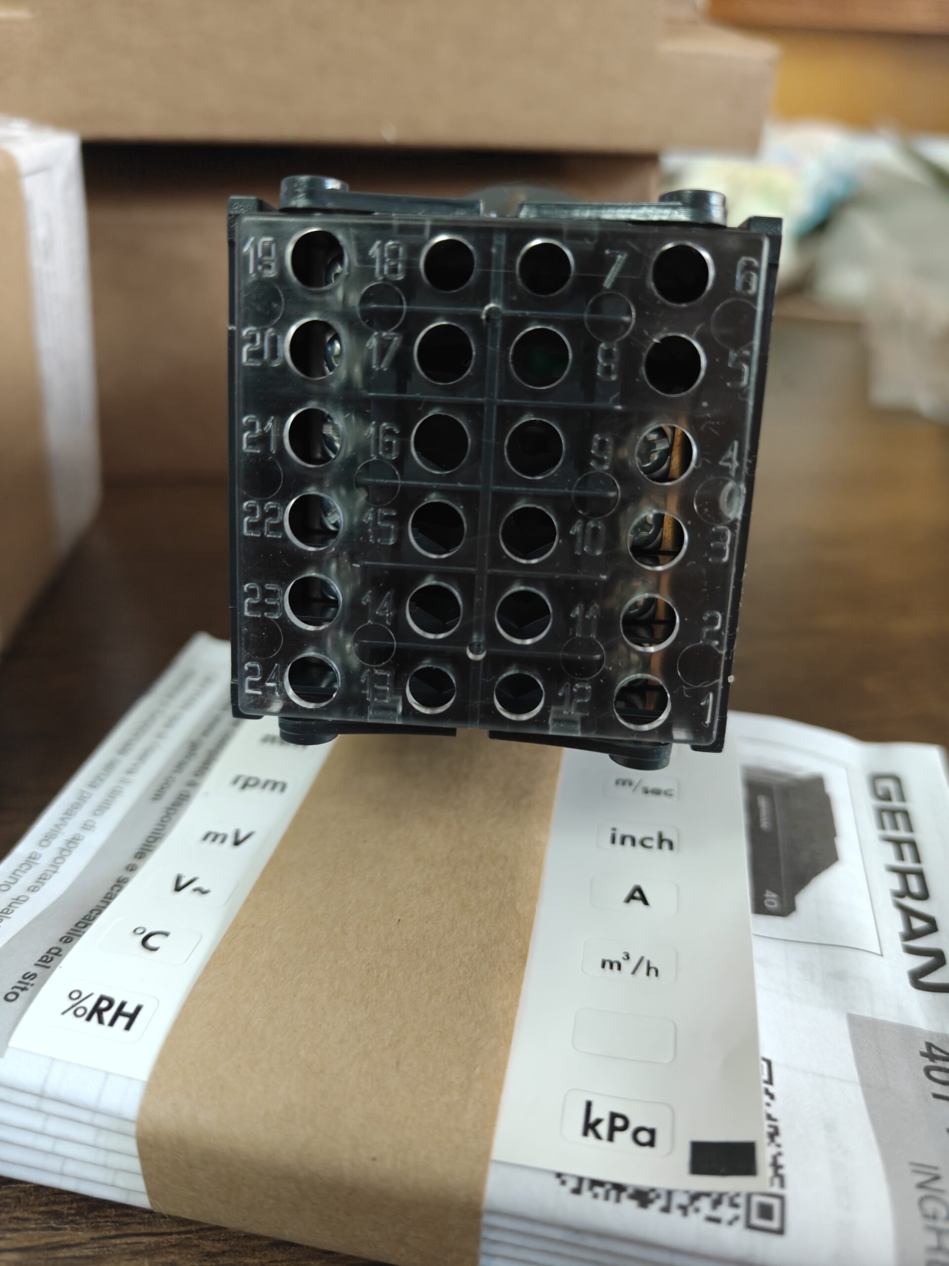

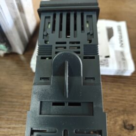
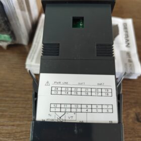
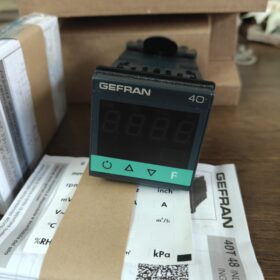
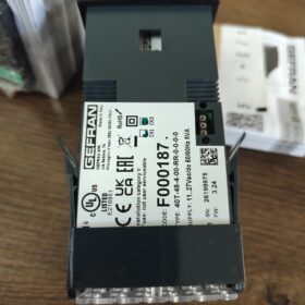
| Feld | Code | Beschreibung |
| Serie | 40T | Universal process indicator / alarm unit (Anzeige & Nur Alarm, NOT a PID temperature Regler) |
| Panel size | 48 | 48×48mm (1/16 AUS, ausgeschnitten: 45×45mm) |
| Display digits | 4 | 4-digit LED display |
| Transmitter supply | 0 | No built-in sensor power supply |
| Ausgabe 1 + Ausgabe 2 | RR | OUT1=Relay; OUT2=Relay |
| Bewertung: 5A / 250VAC, Normalerweise geöffnet (NEIN) Kontakt | ||
| 3rd output | 0 | No 3rd relay output |
| Digitaler Eingang / Analog retransmission | 0 | No digital DI, no 4~20mA analog retransmission output |
| Kommunikationsschnittstelle | 0 | No RS485 communication (Modbus unsupported) |
| Stromversorgung | 0 | 11~27 VAC/VDC universal AC/DC power supply |
| (Suffix 1 = 100~240VAC wide-range power) |
- Wichtigste technische Spezifikationen
- Universeller Eingang (Configurable via front panel buttons)
Thermoelement: K, J, E, T, R, S, B, N, usw.
FTE: Pt100 (2-Draht / 3-Draht)
Linear signals: 4~20mA, 0~20mA, 0~10V, 0~60mV, usw.
- Genauigkeit: ±0.2%FS ±1 digit
- Front panel protection: IP65
- Gesamttiefe: 99 mm
- Probenahmezyklus: 15~120ms adjustable
- Funktionen: Process value display, bis zu 2 independent alarms, sensor break/short circuit detection; No PID control function
- Wichtige Anmerkungen
✅ Positioning: Digital indicator with alarm, cannot directly control temperature; only for monitoring + switch alarm output
❌ No RS485 communication, cannot connect to PLC bus
❌ No 4~20mA retransmission output
❌ No built-in 24V sensor power supply
✅ Compatible with DC24V / AC24V-Stromversorgung
- Gemeinsame Alternative & Variant Models of the Series
40T-48-4-00-RR-0-0-0-1: Power supply changed to 100~240VAC
40T-48-4-00-RR-0-2-0-0: Equipped with additional 4~20mA analog retransmission output
40T-48-4-24-RR-0-0-0-0: Built-in 24V transmitter power supply
GEFAHR 40T-48-4-00-RR-0-0-0-0 Dimension Parameters
- Gesamtdimension (B × H × Tiefe)
48 mm × 48 mm × 99 mm
Standard 1/16 DIN form factor
- Cabinet mounting cutout dimension
45 mm × 45 mm
Recommended machining tolerance: +0.5mm
- Ergänzende Angaben
Front panel rating: IP65
Instrument rear depth (im Schrank): 99mm; reserve ≥105mm internal space for wiring during cabinet design
Model 40T-96 in the same series is horizontal 96×48 version, nicht verwechseln
GEFRAN 40T-48 Measurement Accuracy
Official Nominal Accuracy
- Thermoelement / RTD Input
±0.2% Full Scale (FS) ±1 digit
Testbedingung: Ambient temperature 25℃
- Linear Analog Input (mV, 0~10V, 0/4~20mA)
±0.2% Full Scale (FS) ±1 digit
Temperaturdrift
When ambient temperature deviates from 25℃:
≤ ±0.01% FS / ℃
Important Supplementary Notes
- Auflösung: 4-digit LED display, minimum display unit 1 Ziffer
- Accuracy only refers to instrument itself, excluding sensor error
- Alarm actuation accuracy follows measurement accuracy with no additional deviation
- Einschränkung: No PID regulation, only measurement & Alarm; no control accuracy index
Practical Example
Range set as 0~200℃:
Maximum instrument measurement error ≈ ±0.4℃ ±1 digit
GEFAHR 40T-48-4-00-RR-0-0-0-0 Ausgabekonfiguration
Model output segment: …00-RR-0-0-0-0
- RR = OUT1, OUT2
- 7th digit `0`: No 3rd output
- 8th digit `0`: No analog retransmission output
- 9th digit `0`: No communication interface
- Onboard Outputs
2 Relaisausgänge
Kontaktformular: Normalerweise geöffnet (NEIN)
Kontaktbewertung: 5A / 250VAC; 5A / 30VDC (ohmsche Last)
Anwendung: High/low limit alarm, limit switch signal; can drive small contactors and indicator lights
✅ Feature: Independent alarm outputs; alarm value and mode (high/low limit, deviation alarm, usw.) can be configured separately
- Outputs NOT available on this model
- ❌ No 4~20mA / 0~10V analog retransmission output (digit = 0, nicht 2)
- ❌ No SSR drive voltage output
- ❌ No RS485 Modbus communication
- ❌ No NPN/PNP transistor logic output
- ❌ No PID control output (this unit is only for monitoring & Alarm, incapable of temperature regulation)
- Optional Output Combinations of the Series (for model selection reference)
RR: Dual relay (aktuelles Modell)
RS: OUT1 Relay + OUT2 SSR drive output
SS: Dual SSR drive outputs
Suffix digit `2`: Extra 4~20mA analog retransmission output
Suffix digit `4`: RS485 Modbus RTU interface
Wiring Reminder
Relays are passive dry contacts. External power supply is required. The instrument does not supply internal power to contacts; do not connect directly to sensor circuits.
GEFAHR 40T-48-4-00-RR-0-0-0-0 Relay Operation Mode
✅ Both OUT1 and OUT2 relays support custom configuration via front panel
Beachten: This is a digital alarm indicator without PID control. Relays can only be used as alarm outputs, not temperature control outputs.
- Configurable Alarm Modes (Independent for two relays)
- Absolute High Alarm (Hi)
Relay energizes when measured value setpoint
- Absolute Low Alarm (Lo)
Relay energizes when measured value < Sollwert
- Deviation Alarm (Positiv / Negative Deviation)
Trigger based on deviation relative to setpoint (commonly used for differential monitoring)
- Sensor Break Alarm
Relay activates on thermocouple/Pt100 open circuit or signal over-range
- Adjustable Auxiliary Parameters
Alarm Hysteresis: Prevent relay rapid cycling (chatter)
Alarm Latch: Relay stays energized after alarm trigger; manual panel reset required
Power-up Alarm Suppression: Temporarily disable alarms at startup to avoid false triggering
Contact Logic: Select energized on alarm OR de-energized on alarm
- Kritische Einschränkungen
- Hardware contacts are Normally Open dry contacts. Physical hardware cannot be changed to Normally Closed; “de-energized on alarm” is realized purely by software logic.
- Cannot be configured as PID on/off control output (40T series is indicator, not PID controller like 400 / 2500 Serie).
- OUT1 and OUT2 work independently; combination such as high limit on one channel and low limit on the other is supported.
- Parameter Access Procedure
Lange drücken [F key] für 2 seconds → Enter default password 99
Navigate within `CFG` menu group:
o.1: OUT1 alarm setpoint
o.2: OUT2 alarm setpoint
Select alarm type, Hysterese, latch function and power-up suppression in corresponding submenus





NH42-63-318x560.png "Automatische Transferschalter vom Typ CHINT PC (ATS)NH42-63/4SZ")



