 Schütz,Leistungsschalter,Sensor,Encoder,SPS,Konverter

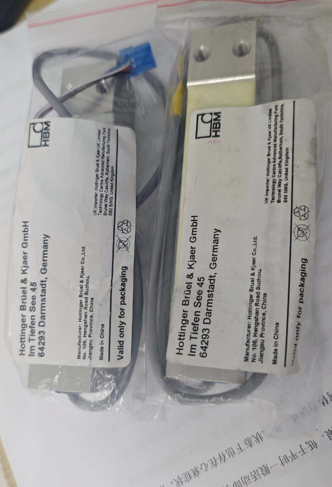

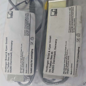
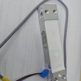
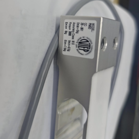
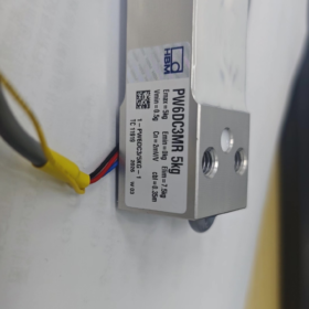
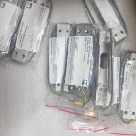
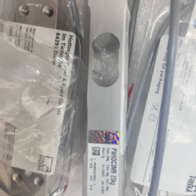
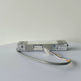
PW6DC3MR/XXkg
PW6D: Produktserie, Einzelpunkttyp, optimiert für dynamisches Hochgeschwindigkeitswägen
C3: Genauigkeitsklasse von 3,000 Eichabteilungen gemäß OIML R60
MR = Mehrbereich: Im Vergleich zur Standard-C3-Version, Es unterstützt ein kleineres Mindestüberprüfungsintervall, geeignet für Mehrbereichswaagen
XXkg: Nennkapazität (3/5/10/15/20/30/40kg)
Vollständiges Beispiel für ein Bestellmodell: 1-PW6DC3MR/10KG-1
- Kernspezifikationen
- Kapazitätsoptionen
3kg, 5kg, 10kg, 15kg, 20kg, 30kg, 40kg
- Elektrische Parameter
Nennleistung: 2.0 mV/V
Brückeneingangswiderstand: ~350 Ω
Empfohlene Erregerspannung: 5~12V DC (Max. 15 In DC)
Konstruktion: 6-Drahtdesign (Kabel kann gekürzt werden) um Messfehler zu vermeiden, die durch Kabelspannungsabfall verursacht werden; kompatibel mit 4-Draht-Instrumenten
Isolationswiderstand: >2000 MΩ
- Genauigkeit & Zertifizierungen
OIML R60 C3MR, nLC=3000 Divisionen
Kompensation außermittiger Last gemäß OIML R76; maximale Plattformabmessung für eine einzelne Wägezelle: 300×300 mm
Nichtlinearität / Hysterese / Wiederholbarkeit: ≤±0,017 %FS
- Mechanisch & Umweltspezifikationen
Material: Aluminiumlegierung
Schutzklasse: IP67
Bewertete Durchbiegung: 0.18~0,29 mm (Hohe Steifigkeit, schnelle dynamische Reaktion)
Kompensierter Temperaturbereich: -10 ℃ ~ +40 ℃
Betriebstemperaturbereich: -10 ℃ ~ +50 ℃
Sichere Überlastung: 150%FS; Ultimative Überlastung: 300%FS
Befestigungsschraube: M6; Empfohlenes Anzugsdrehmoment: 10 N·m
- Hauptvorteile
✅ Optimiert für dynamisches Wiegen: Hohe Eigenfrequenz, ideal for high-speed checkweighing and volumetric filling
✅ Built-in off-center load compensation to minimize platform eccentricity error
✅ IP67 sealing, applicable in dusty and humid production environments
✅ 6-wire shielded cable ensures stable signal for long-distance wiring
✅ MR multi-range variant supports smaller verification intervals, compliant for legally verified commercial weighing equipment
- Typische Anwendungen
Inline checkweighers, weight sorting machines
Small-scale automatic packaging, Pulver & particle filling equipment
Industrial platform scales, multi-head combination weighers
Dynamic weight monitoring on automated production lines
- Verkabelungsdefinition (Standard 6-Wire Shielded Cable)
| Signal | Typical Wire Color |
| +Exc Excitation Positive | Blau |
| -Exc Excitation Negative | Schwarz |
| +Sense Sense Positive | Grün |
| -Sense Sense Negative | Grau |
| +Sig Signal Positive | Weiß |
| -Sig Signal Negative | Rot |
| Schild | Green/Yellow |
For 4-wire instruments: Schließen Sie +Sense mit +Exc kurz, und -Sense bis -Exc
- Gleiche Serie & Alternative Referenzen
- PW6DC3: Standard-C3-Genauigkeit (Nicht-MR), geringere Kosten, Kleine Überprüfungsintervalle für mehrere Bereiche können nicht unterstützt werden
- PW2DC3MR: Kleinere Single-Point-Wägezelle von HBM, mit kleinerer maximal zulässiger Plattformgröße
- Inländische Alternativen: Einzelpunkt-C3-Wägezellen von Zemic, A&D, Elektronische Messgeräte von Zhonghang. Überprüfen Sie die Anordnung der Montagelöcher, mV/V-Bewertung und maximale Plattformgröße vor dem Austausch.
- Vorsichtsmaßnahmen bei der Installation
- Montageflächen müssen eben und stabil sein. Das Wägezellengehäuse nicht schweißen oder anschlagen.
- Ziehen Sie die M6-Schrauben fest an 10 N·m, um ein Abisolieren des Gewindes am Aluminiumgehäuse zu vermeiden.
- Die Belastung muss senkrecht nach unten erfolgen; Vermeiden Sie seitliche Kraft- und Drehmomenteinwirkungen.
- Vermeiden Sie mechanische Biegungen und Spannungen am Kabelausgang; Zur Abschirmung wird eine einseitige Erdung empfohlen.
Vollständiger Leitfaden zur Auswahl von Wägezellen (Abgebildet mit HBM PW6DC3MR Single-Point-Wägezelle)
Schritt 1: Bestätigen Sie den Typ der mechanischen Struktur (Höchste Priorität)
Passen Sie die Struktur der Wägezelle an den Lastzustand an:
| Anwendungsszenario | Empfohlener Typ | Anwendbarkeit für PW6DC3MR |
| Einzelne Wägezelle, die eine Plattform unterstützt, Kontrollwaage, kleiner Verpackungsmaßstab | Einzelpunkt-Wägezelle ✅ | PW6DC3MR ist ein Single-Point-Typ. Eingebauter Exzentrizitätsausgleich; Eine Plattform erfordert nur eine Wägezelle |
| Materialtrichter, Mülleimer, Plattformwaagen mit mehreren Zellen | Scherbalken / Auslegerbalken | ❌ Gilt nicht für PW6D |
| Spannungswägung, hängende Waage | S-Beam-Wägezelle | ❌ Gilt nicht für PW6D |
| Schwerlast-LKW-Waagen, Tankwägung | Spalte / Speichen-Wägezelle | ❌ Gilt nicht für PW6D |
Harte Einschränkung von PW6DC3MR: Maximale Plattformdimension: 300×300 mm. Eine Plattform, die diese Größe überschreitet, führt zu übermäßigen Exzentrizitätsfehlern.
Schritt 2: Kapazitätsberechnung (Der häufigste Fallstrick bei der Auswahl)
Berechnungsformel
Nennkapazität der Wägezelle ≥ (Eigengewicht der Plattform + Maximales Produktgewicht) × Sicherheitsfaktor
Stable static weighing: Safety factor 1.2~1.3
Dynamic checkweighing, material drop impact, vibrating production line: 1.5~2.0 (1.5 empfohlen)
Practical Example (PW6DC3MR)
Platform dead weight = 1.5kg, maximum product weight = 10kg, inline dynamic checkweighing:
Total load = 1.5 + 10 = 11.5kg; 11.5 × 1.5 = 17.25kg
Priority selection: PW6DC3MR/20KG. Avoid 15kg (unzureichende Marge) and excessive 30kg capacity (poor resolution for light loads).
⚠️ Two critical rules:
- Do not operate continuously near full capacity;
- Do not oversize capacity excessively, which degrades resolution for low-weight measurement.
Schritt 3: Accuracy Class Selection (C3 / C3MR / C6 Comparison)
Take HBM PW6D series as example:
- C3: Standard 3000 divisions, for general industrial weighing, unable to achieve ultra-small verification intervals
- C3MR (Ihr Modell): Multi-Range variant, OIML R60 certified, supports smaller minimum verification interval (Vmin)
✅ Geeignet für Geräte, die eine gesetzliche Messtechnikzertifizierung erfordern, Hochgeschwindigkeits-Kontrollwägen, volumetrische Füllung und hohe Anzeigeauflösung (Messung im Grammbereich)
- C6: 6000 divisions, höhere Präzision, höhere Kosten, strengere Anforderungen an die Montagesteifigkeit und die Betriebsumgebung
Schnellauswahlregel für C3 vs. C3MR
Die Ausrüstung erfordert eine kommerzielle messtechnische Zertifizierung, hochpräzises Kontrollwägen, kleinräumiges Intervall (Gramm-Ebene) → PW6DC3MR
Nur interne Prozessüberwachung, keine Wiegebescheinigung erforderlich, lose Genauigkeitsanforderungen → PW6DC3 (Standardversion)
Wichtige Genauigkeitsindikatoren zur Überprüfung: Nichtlinearität, Hysterese, Wiederholbarkeit, kriechen, Temperaturdriftfehler.
Schritt 4: Betriebsumgebung, Material & Schutzklasse
- Material
PW6DC3MR: Aluminiumlegierung; Geeignet für trockene Standardlebensmittel und automatisierte Werkstätten.
Zum Abwaschen, feucht oder ätzend / Salznebelumgebungen: Bevorzugen Sie Einzelpunkt-Wägezellen aus Edelstahl.
- Schutzklasse
PW6D: IP67, staubdicht und spritzwassergeschützt; NICHT für dauerhaftes Untertauchen geeignet.
Für vollständig gewaschene Ausrüstung oder Unterwasserinstallation: Es sind hermetisch abgedichtete Wägezellen gemäß IP68 erforderlich.
- Temperaturbereich
Kompensierter Bereich: -10~+40℃; Ein längerer Betrieb außerhalb dieses Bereichs führt zu einer starken Nullpunktdrift. Für extreme Temperaturbedingungen werden kundenspezifische Modelle mit breitem Temperaturbereich benötigt.
- Explosionsschutz: Für explosionsgefährdete Bereiche, Verwenden Sie eigensichere, zertifizierte Wägezellen. Der Standard PW6DC3MR ist nicht explosionsgeschützt.
Schritt 5: Elektrische Parameteranpassung mit dem Instrument
- Empfindlichkeit: PW6DC3MR = 2.0 mV/V, die gebräuchlichste Spezifikation für industrielles Wägen; Bestätigen Sie die Gerätekompatibilität.
- Verkabelungstyp: PW6D verwendet 6-Draht (mit Sense-Feedback-Leitungen)
Instrument, das 6-Draht unterstützt: Vollständige Verkabelung zur Vermeidung von Kabelspannungsabfällen
Das Instrument unterstützt nur 4-Draht: Schließen Sie +Sense mit +Exc kurz, -Sinn bis -Exc
- Erregerspannung: Empfohlen 5~12 V DC, maximal 15 In DC
- Brückenwiderstand: ~350 Ω Eingangswiderstand, kompatibel mit Standard-Wägetransmittern
Schritt 6: Überprüfung der mechanischen Abmessungen (Leicht übersehen)
- Gesamtlänge, Höhe, Montagelochabstand, Thread-Spezifikation (PW6D verwendet M6-Befestigungsschrauben)
- Mechanischen Einbauraum prüfen
- Sorgen Sie für eine vertikale Lastübertragung; Die Strukturkonstruktion muss Querkräfte und Drehmomente eliminieren
PW6D-Montagedrehmomentstandard: Anzugsdrehmoment der M6-Schraube 10 N·m. Beim Aluminiumgehäuse besteht die Gefahr einer Gewindeschädigung bei übermäßigem Drehmoment.
Schritt 7: Unterscheiden Sie Dynamik / Statische Anwendungsszenarien
Statisches Wiegen (Lagerplattformwaage): Standard C3 ist ausreichend; Priorisieren Sie die langfristige Nullstabilität
Dynamisches Wiegen (Inline-Kontrollwaage, Online-Sortierung): PW6DC3MR bevorzugt; optimierte hohe Eigenfrequenz, schnelle Reaktion und Vibrationsfestigkeit
Checkliste für häufige Auswahlfehler
❌ Berücksichtigen Sie nur das maximale Produktgewicht ohne Berücksichtigung des Eigengewichts der Plattform
❌ Verwenden Sie die Einzelpunkt-Wägezelle PW6D für Plattformen mit einer Größe über 300×300 mm, Dies führt zu einem übermäßigen Exzentrizitätsfehler
❌ Nehmen Sie einen Sicherheitsfaktor von nur an 1.2 unter dynamischer Einwirkung, Dies führt zur Ermüdung des elastischen Elements und zu dauerhaften Schäden
❌ Kaufen Sie den Standard C3 anstelle von C3MR, wenn eine Wägezertifizierung erforderlich ist, Nichterfüllung der Mindestskalierungsintervallanforderungen
❌ Wählen Sie eine Aluminium-Wägezelle mit Schutzart IP67 für nasse Umgebungen mit feuchter Umgebung, Dies führt zu langfristigem Wassereinbruch und vorzeitigem Ausfall
❌ Eine zu große Kapazität führt bei leichten Produkten zu instabilen Messwerten und einer schlechten Auflösung
Schnellauswahlvorlage (Bereit für den direkten Einsatz)
- Struktur: Einzelpunkt ✅ (Plattform ≤300×300 mm)
- Gesamtlast: Plattform ____kg + Maximales Produkt ____kg = ____kg × Sicherheitsfaktor ____ = ____kg → Ausgewähltes Modell PW6DC3MR/____kg
- Genauigkeit: Messtechnische Zertifizierung erforderlich? Ja → C3MR; Nein → C3
- Umfeld: Trockene Werkstatt, IP67 akzeptabel; Abwaschen / korrosive Umgebung → auf Edelstahl-Wägezelle umstellen
- Elektrisch: Instrumentenstützen 2.0 mV/V; Bestätigen Sie die 6-Draht- oder 4-Draht-Verkabelung
- Installation: Dimension überprüfen, M6-Montageraum, vertikale Kraftübertragungsstruktur
So bestimmen Sie die Montageposition von Wägezellen
Erklärung basierend auf der Einzelpunkt-Wägezelle PW6DC3MR von HBM (Einzelzellenplattform); Allgemeine Regeln für Mehrzellen-Wägeplattformen sind ebenfalls enthalten.
- Unterscheiden Sie zwei Strukturtypen: Single-Point vs. Multi-Cell
(1) Einzelpunkt-Wägezelle (PW6DC3MR, einzelne Zelle, die eine Plattform unterstützt)
Einzelpunkt-Wägezellen verfügen über einen integrierten außermittigen Lastausgleich.
Standard-Montageposition: Geometrische Mitte der Plattformunterseite
✅ Optimale Anordnung:
Richten Sie die Mitte der tragenden Öffnung der Wägezelle auf die Längen- und Breitenmitte der Plattform aus.
Maximal zulässige Plattformdimension: 300 × 300 mm (PW6D-Spezifikationsgrenze)
⚠️ Kritische Einschränkungen:
Wenn die Wägezelle von der Mitte abweicht:
Der Exzentrizitätsfehler nimmt zu
Inkonsistente Messwerte, wenn das Gewicht an vier Ecken angebracht wird
Selbst eine zentrierte Installation kann Fehler nicht kompensieren, wenn die Plattform die maximale Abmessungsgrenze des Herstellers überschreitet
Praktische Methode: Zeichnen Sie zwei Diagonalen der rechteckigen Plattform; Der Schnittpunkt ist die mittlere Montageposition.
(2) Mehrzellige Struktur (3/4 Cantilever-/Scherstab-Wägezellen, Plattformwaagen, Lagertrichter)
Die Einbaulage folgt dem Prinzip der gleichmäßigen Lastverteilung entsprechend dem Schwerpunkt
- Rechteckige Plattform mit vier Wägezellen: Symmetrisch in der Nähe von vier Ecken angeordnet
- Runder Lagerbehälter mit drei Wägezellen: Gleichmäßig in einem gleichseitigen Dreieckslayout verteilt
- Ziel: Die von jeder Wägezelle getragene Last muss unter Leer- und Volllastbedingungen möglichst gleichmäßig sein
- Fünf universelle Prinzipien für alle Wägesysteme
Prinzip 1: Der kombinierte Schwerpunkt muss innerhalb der Tragfläche der Wägezellen liegen
- Unbeladener Zustand: Der Eigengewichtsschwerpunkt der Plattform liegt innerhalb der Auflagefläche
- Voll beladener Zustand: Wenn Material mit maximaler Exzentrizität platziert wird, Der Gesamtschwerpunkt bleibt innerhalb der Stützhülle
Wenn sich der Schwerpunkt außerhalb des Auflagebereichs bewegt: Kippgefahr der Plattform, und die Wägezelle trägt enorme seitliche Kräfte und Drehmomente, zu bleibenden Schäden führen.
Prinzip 2: Eliminieren Sie seitliche Kräfte und Drehmomente auf Wägezellen
Wägezellen dürfen nur vertikale Druckkräfte aufnehmen
❌ Verbotene Bedingungen:
Durch schiefe Einbaulage erzeugte seitliche Kraftkomponente
Drehmoment durch unzureichende Steifigkeit des Stützrahmens
✅ Lösung:
Entwerfen Sie mechanische Anschläge zur horizontalen Begrenzung. Halten Sie einen geringen vertikalen Abstand ein; Anschläge dürfen keine vertikale Last tragen.
Prinzip 3: Sorgen Sie für eine vertikale Kraftübertragung
Die tragende Fläche der Wägezelle muss parallel zur Unterseite der Wägeplattform sein.
Die Montagebasis muss flach und stabil sein; Vermeiden Sie dünne Plattenaufhängungen und örtlich konzentrierten Kontakt.
Das Aluminiumgehäuse des PW6DC3MR verhindert eine punktuelle Kontaktbelastung.
Prinzip 4: Vermeiden Sie starke Vibrationsquellen und thermische Ausdehnungsspannungen
Auswahl der Montageposition:
Halten Sie Abstand zu starken Vibrationsquellen wie Motoren und Förderrollen
Die thermische Ausdehnung/Kontraktion langer Rahmen kann zu einer Belastung der Wägezelle führen; Bei Bedarf ist eine verschiebbare Stützstruktur erforderlich
Prinzip 5: Vermeiden Sie Zugbelastungen am Kabelausgang
Der Kabelabgang des PW6DC3MR befindet sich am Ende des Sensors.
Anordnungsvoraussetzung: Durchhängende Kabelschlaufen reservieren; Vermeiden Sie Spannungen und wiederholtes Biegen an der Kabelwurzel, um einen inneren Drahtbruch zu verhindern.
- Schritt-für-Schritt-Positionierung für die Single-Point-Plattform (PW6DC3MR)
- Außenmaß der Plattform messen: Länge L × Breite B
- Berechnen Sie die Mittelpunktskoordinaten: L/2, W/2
- Richten Sie die Mitte der tragenden Bohrung der Wägezelle auf den berechneten Mittelpunkt aus
- Überprüfung der Plattformabmessungen:
≤300×300 mm: Normale zentrierte Installation
>300×300 mm: PW6D kann nicht verwendet werden. Wechseln Sie zu einer größeren Einzelpunkt-Wägezelle oder einer Mehrzellenlösung
- Überprüfung des Gewichtstests:
Platzieren Sie die Kalibriergewichte nacheinander an vier Ecken der Plattform und beobachten Sie die Abweichung der Messwerte.
Ein übermäßiger Vier-Ecken-Fehler weist entweder auf eine versetzte Wägezellenposition oder eine übergroße Plattform hin.
- Vier-Ecken-Positionierungsvorgang für eine Multizellenplattform (4 Beispiel einer Wägezelle)
- Symmetrisches Layout; Vier Stützpunkte bilden ein Rechteck
- Lassen Sie einen ausreichenden Abstand zwischen den Stützpunkten und der Plattformkante; Vermeiden Sie es, zu nah an Kanten zu platzieren
- Grobe Nivellierung bei Leerlast mit Vorspannung
- Führen Sie eine Vier-Ecken-Fehlerkalibrierung durch, nachdem Sie an jeder Ecke Gewichte geladen haben
- Installieren Sie mechanische Anschläge, um zu verhindern, dass die Plattform bei Stößen verrutscht
- Häufige Fehler bei der Montageposition
- Einzelpunkt-Wägezelle außerhalb der Plattformmitte installiert → inkonsistente Messwerte an vier Ecken
- Übergroße Plattform verwendet immer noch die Einzelpunkt-Wägezelle PW6D → übermäßiger Exzentrizitätsfehler
- Unzureichende Steifigkeit des Stützrahmens; Eine Rahmenverformung unter Last erzeugt ein Drehmoment auf die Wägezelle
- Verriegelte mechanische Anschläge; Durch die thermische Ausdehnung entsteht eine zusätzliche Kraft, die zu einer kontinuierlichen Nullpunktdrift führt
- Wägezellen zu nah an Kanten angeordnet; Der Schwerpunkt verschiebt sich außerhalb des Stützbereichs, wenn das Material exzentrisch platziert wird
- Die Riemenspannung erzeugt eine horizontale Zugkraft, die auf die Wägezelle von Inline-Kontrollwaagen übertragen wird (Unabhängiger Rahmen zur Isolierung der Riemenspannung erforderlich)
- Zusätzliche Ratschläge für Ihre Ausrüstung (Kontrollwaage mit PW6DC3MR)
Für Inline-Kontrollwaagen: Der Rahmen des Bandförderers darf nicht starr an der Wiegeplattform befestigt sein.
Fördermotor und Bandspannung erzeugen eine kontinuierliche horizontale Zugkraft.
Empfohlene Lösung: Nur die Wiegeplattform trägt Produkte; Der Förderrahmen steht unabhängig auf dem Boden, um horizontale Kräfte zu isolieren.





NH42-63-318x560.png "Automatische Transferschalter vom Typ CHINT PC (ATS)NH42-63/4SZ")



