 Schütz,Leistungsschalter,Sensor,Encoder,SPS,Konverter

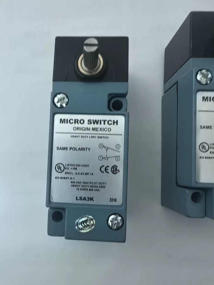

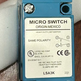
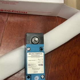
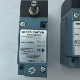
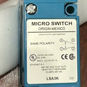
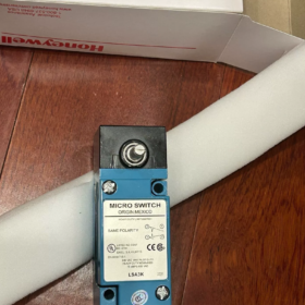
(Hochleistungs-Seitendreher der HDLS-Serie Endschalter, auch als Micro LSA3K bezeichnet)
Modellinterpretation
LSA3K: Schwerlast-Endschalter HDLS, Nicht steckbarer Körper, Seitlicher Drehantriebskopf, SPDT (Einpoliger Doppelwurf), Schraubklemmenverkabelung, NPT1/2-Leitungsanschluss
Marke: Honeywell MIKROSCHALTER, Hergestellt in den USA
Grundlegende elektrische Spezifikationen
| Artikel | Spezifikation |
| Kontaktkonfiguration | SPDT 1NO+1NC, Doppelunterbrechende Schnappkontakte |
| Nennstrom | 10 A |
| Max. Wechselspannung | 600 VAC |
| Max. Gleichspannung | 250 VDC |
| Beendigung | Schraubklemmen (Nicht-Plug-In) |
| Betriebsmodus | Momentan; betätigbar im Uhrzeigersinn / Drehung gegen den Uhrzeigersinn |
Mechanisch & Umweltspezifikationen
Aktuator: Seitlich drehbare Welle, Max. Betriebsdrehmoment 0,45 N·m (4 in-lb)
Vor der Reise: Max. 15°; Überfahrt: Min. 60°
Betriebstemperatur: -12℃ ~ +121℃
NEMA-Bewertungen: 1, 3, 4, 4X, 6, 6P, 12, 13 (Im Freien, staubdicht und wasserbeständig)
Leitungseinführung: 1/2-14 NVV
HS-Code: 8536509055
Typische Anwendungen
Baumaschinen, Anhänger, Bewässerungsausrüstung, Rückmeldung der Ventilstellung, HVAC, Prüfgeräte, Positionsbegrenzung für schwere Maschinen, Bewegungserkennung von Materialtransportgeräten.
Für eine bequeme Inbetriebnahme kann der Drehkopf direkt neu ausgerichtet werden, ohne das Schaltergehäuse zu demontieren.
Schneller Vergleich ähnlicher Serienmodelle
- LSA1A: Steckkörper, Ansonsten funktionell ähnlich wie LSA3K
- LSA3K: Nicht Plug-In, Schraubklemme (Zielmodell)
- LSP3K: Kolbentyp (nicht rotierender Kopf), Nicht steckbarer Körper
Inländische Ersatzreferenz
Ersatzanforderungen: Typ mit seitlichem Drehhebel, SPDT, 10 A, Hochschutz NEMA4X / IP67, Schraubklemmen, großer Betriebstemperaturbereich
Inländische Alternativen: WL-SD (seitendrehend), AZ5104, JDHK-3Y. Bitte überprüfen Sie das Betriebsdrehmoment, Reisewinkel, Spezifikationen für Leitungsgewinde.
Lange Vorlaufzeit für das Originalgerät (ca. 18 Wochen OEM-Vorlaufzeit). Gebrauchte Geräte sind auf dem Gebrauchtmarkt weit verbreitet. Inspektionscheckliste für gebrauchte Schalter:
- Überprüfen Sie die Drehwelle auf gleichmäßige Drehung ohne Blockierung;
- Bestätigen Sie NEIN / Öffnerkontaktschaltung mit Multimeter;
- Gehäuse auf Risse und intakte Dichtung prüfen.
Honeywell MIKROSCHALTER LSA3K (Hochleistungs-Endschalter der HDLS-Serie) Installationsanweisungen
Entsprechendes OEM-Dokument: Installationsanweisungen für die HDLS-Serie (Dok. Nr.81116-6). LSA3K ist nicht steckbar und verfügt über einen seitlich drehbaren Betätigungskopf.
⚠️WARNUNG: Dieser Schalter darf NICHT als Not-Aus- oder Sicherheitsschutzvorrichtung verwendet werden. Ein Versagen kann zu Verletzungen oder zum Tod führen. Verwenden Sie für sicherheitsrelevante Anwendungen spezielle Sicherheitsschalter.
1 Produktinformationen
Modell: LSA3K, HDLS-Serie, Nicht steckbarer Körper, Schraubklemmen, Seitlich drehbare Antriebswelle, SPDT (1NO+1NC Schnappkontakte)
Leitungsanschluss: 1/2-14 NVV
Gehäuse: Zinkdruckgusslegierung; NEMA 1/3/4/4X/6/6P/12/13; IP67 staubdicht und wasserbeständig
Parameter der Antriebswelle: Max. Betriebsdrehmoment 0,45 N·m (12-16 in-lb); Max. Vorlauf 15°; Min. Nachlauf 60°; im und gegen den Uhrzeigersinn betätigbar.
2 Mechanische Installation
2.1 Zwei Montagemethoden
1) Frontmontage (Empfohlen): Mit zwei befestigen 10 Schrauben Sie die Schrauben durch die Befestigungslöcher an der Vorderseite des Gehäuses.
2) Hintere Montage: Benutzen Sie zwei 10-32 UNF-Schrauben werden von der Geräterückplatte aus in Innengewindelöcher auf der Rückseite des Gehäuses eingeschraubt.
Auf starrem Metallsockel montieren. NICHT auf dünnem Untergrund installieren, Leicht verformbare Platten, die starken Vibrationen ausgesetzt sind.
2.2 Anzugsdrehmoment
Befestigungsschrauben des Schalters: 1.4-1.8 N·m (12-16 in-lb). NICHT zu fest anziehen; Es kann zu Rissen und Verformungen am Gehäuse kommen.
Feststellschraube des Betätigungshebels: Ziehen Sie den Hebel fest, bis die verdrehsichere „Teller-Lasche“ ausweicht, Bestätigung der sicheren Verriegelung, um ein Abrutschen des Hebels bei Vibration zu verhindern.
2.3 Richtlinien zur Aktuatorausrichtung (Seitlich rotierende Welle)
- Antriebsmechanismus (Nocken / Hund) dreht die Schaltwelle. Stellen Sie sicher, dass der Nachlauf mindestens ≥60° beträgt. Halten Sie NICHT innerhalb der Reichweite vor der Fahrt an. Vermeiden Sie es, den mechanischen Endanschlag zu überschreiten, um Schäden an der Welle zu vermeiden.
- Es darf keine seitliche Radiallast ausgeübt werden; Es ist nur ein Drehmoment zulässig.
- Die Ausrichtung des Drehkopfes kann direkt angepasst werden, ohne dass das Schaltergehäuse geöffnet werden muss.
- Vermeiden Sie die Installation an tiefen Stellen, an denen sich Kondensat ansammelt. Richten Sie den Rohranschluss am tiefsten Punkt der Rohrleitung nicht nach unten aus, um das Eindringen von Kondensat zu verhindern.
2.4 Leitungsabdichtung
Tragen Sie PTFE-Band oder Rohrdichtmittel auf 1/2-14NPT-Gewinde auf, um die Umweltverträglichkeit aufrechtzuerhalten. Eindringendes Wasser führt zu Kontaktkorrosion und vorzeitigem Ausfall.
Verhindern Sie, dass überschüssiges Dichtmittel in das Innere des Schalters drückt.
3 Elektrische Verkabelung
Trennen Sie vor der Verkabelung die gesamte Stromversorgung. Beachten Sie die örtlichen Elektrovorschriften. LSA3K verwendet Schraubklemmen (Nicht-Plug-In) mit interner Schutzleiterklemme.
- Entfernen Sie die Schrauben der Abdeckung und öffnen Sie den Anschlussraum.
- Terminalidentifikation: COM (Gemeinsam), NEIN (Normalerweise geöffnet), NC (Normalerweise geschlossen); Es ist eine eigene Schutzerdungsklemme vorhanden.
- Verdrahtung: Verwenden Sie verseilte Kupferleiter. Klemmschrauben festziehen; Begrenzen Sie die Länge des freiliegenden blanken Leiters, um einen Kurzschluss zu vermeiden. Verhindern Sie, dass Kabelreste in das Gehäuse fallen.
- Elektrische Nennwerte: Max. 600VAC, 10 Ein Widerstand; Max. 250 VDC.
- Nach der Verkabelung, Bestätigen Sie die Unversehrtheit der Dichtung, Deckel wieder aufsetzen und Deckelschrauben gleichmäßig festziehen.
Schaltung: SPDT einpoliger Doppelschalter, Schnappverschluss, momentan (keine Verriegelung).
4 Inbetriebnahmeverfahren
- Stellantriebswelle manuell betätigen. Die Rotation muss gleichmäßig sein und darf nicht klemmen oder kleben.
- Multimetertest: COM-NC führt im Freistaat; Kontakte schnappen beim Betätigungswinkel auf COM-NO-Leitung um; Automatischer Reset bei Freigabe.
- Simulieren Sie Maschinenbewegungen: Bestätigen Sie, dass der mechanische Mitnehmer den Schalter zuverlässig in den Überlauf treibt, ohne die Welle zu blockieren.
- Stellen Sie sicher, dass die Gehäuse- und Leitungsabdichtung vollständig abgeschlossen ist.
5 Umfeld & Wartung
Betriebstemperatur: -12℃ ~ +121℃
Regelmäßige Inspektion: Überprüfen Sie den festen Sitz der Befestigungsschrauben, Hebelschlupf, Gehäuserisse und Integrität der Leitungsdichtung.
Zerlegen Sie den internen Schaltmechanismus NICHT. Die interne Kontaktbaugruppe kann nicht gewartet werden; Tauschen Sie bei einem Ausfall die komplette Einheit aus.
6 Häufige Installationsfehler
- Zu hohes Anzugsdrehmoment: Risse im Gehäuse, Verlust des Umweltschutzes.
- Unzureichender Nachlauf: Der Betrieb bleibt im Vorreisebereich; instabile Kontakte und zufällige Fehlfunktionen.
- Fehlende NPT-Gewindedichtung: Wassereinbruch, Kontaktoxidation und -ausfall.
- Entriegelter Hebel: Der Hebel rutscht unter der Vibration, was zu einer Positionsverschiebung führt.
- Verwendung als Not-Aus-Sicherheitsschalter: Verstößt gegen die Designspezifikation, schafft Gefahr.
7 Wichtige Montageabmessungen
Abstand von Mitte zu Mitte der Frontmontagelöcher: ca. 44,2 mm; Lochdurchmesser 5,1 mm.
Leitungsanschluss: Unten angeordnet 1/2-14NPT.
Funktionsprinzip des Honeywell LSA3K (HDLS-Serie)
LSA3K ist ein Hochleistungs-Dreh-Schnappschalter (Mikroschalter). Sein Kernmechanismus wandelt mechanische Drehbewegungen über eine mechanisch angetriebene, federbelastete Schnappkontaktbaugruppe in elektrische Ein-/Aus-Signale um; Es handelt sich um einen Fahrschalter mit Momentrückstellung.
1 Gesamtkonstruktion
- Externe Drehantriebswelle: Angetrieben durch externe Nocken / Hunde; unterstützt Betätigung im und gegen den Uhrzeigersinn.
- Interner Nockenumwandlungsmechanismus: Die Drehbewegung der Außenwelle treibt die Innennocke an, Wandelt Winkeldrehung in linearen Schub um, um die Federkontaktbaugruppe zu betätigen.
- Schnappfederkontaktanordnung (Kern): SPDT mit Doppelunterbrechung (COM-NO-NC). Vorgespannte Federn ermöglichen ein sofortiges Einrasten, kein allmähliches Herstellen und Unterbrechen des Kontakts.
- Schraubklemmenblock und Gehäuse aus Druckgusslegierung bieten staub- und wasserbeständigen Schutz.
Hauptmerkmal: Kontakte werden nicht nach und nach geschlossen. In Federn gespeicherte Energie löst einen sofortigen Zustandsübergang aus, sobald der Schwellenwinkel erreicht ist.
2 Vollständiger Betriebsablauf
Nicht aktivierter Freistaat
Interne Federn halten die Baugruppe in Ruheposition:
COM Common ↔ NC Normalerweise geschlossen: Dirigieren
COM Common ↔ NO Normalerweise offen: Offen
Die Welle befindet sich in der 0°-Ausgangsposition.
Betätigungssequenz (Wellendrehung)
- Der externe Mechanismus dreht die Welle über den Vorlauf (max. 15°).
Die interne Nocke drückt Federn zusammen, um mechanische Energie zu speichern. Während der Vorfahrt erfolgt keine Kontaktumschaltung.
- Welle dreht sich über den Grenzwinkel hinaus; Die gespeicherte Federenergie löst sich zum sofortigen Einrasten aus:
Kontakte werden schnell übertragen: COM-NC öffnet → COM-NO schließt.
Snap-Action-Eigenschaft: Unabhängig von der Drehzahl der Welle, Kontakte schalten sofort um, um Kontaktprellen zu unterdrücken.
- Eine weitere Drehung geht in den Überlauf über (mindestens 60°); Die Kontakte bleiben im geschlossenen Zustand COM-NO.
✅Bei der Installation muss sichergestellt sein, dass die Maschinenantriebe in den Überlauf schalten; Wenn Sie nur innerhalb der Vorlaufposition bleiben, führt dies zu einer instabilen Kontaktleistung.
⚠️Überschreiten Sie nicht den mechanischen Endanschlagwinkel, um Schäden an der Welle zu vermeiden.
Reihenfolge zurücksetzen
Die äußere Antriebskraft wird entfernt. Die interne Rückholfeder drückt die Welle zurück in die Ausgangsposition. Die Kontakte schnappen sofort auf COM-NC-leitend und COM-NO-offen zurück.
👉Momentan, nicht rastend; automatisches Zurücksetzen nach Wegnahme äußerer Krafteinwirkung.
3 Elektrisches Prinzip (SPDT-Doppelunterbrechung)
COM: Gemeinsames Terminal
NC: Normalerweise geschlossen (Dirigieren im Ruhezustand)
NEIN: Normalerweise geöffnet (Leiten nach Betätigung)
Das Doppelunterbrechungsdesign unterbricht beide Seiten des Stromkreises gleichzeitig für eine verbesserte Lichtbogenunterdrückung. Ausgelegt für bis zu 600 VAC / 10 Ein Widerstand und 250 VDC für industrielle Wechsel- und Gleichstromkreise.
4 Wichtige Funktionsprinzipien
- Bidirektionale Betätigung: Das interne Nockendesign ermöglicht die Auslösung sowohl durch Drehung der Welle im Uhrzeigersinn als auch gegen den Uhrzeigersinn.
- Snap-Action (Snap-over) Vorteil:
Kontaktprellen und Lichtbogenbildung werden selbst bei langsamen mechanischen Bewegungen eliminiert. Die sofortige Kontaktübertragung reduziert elektrische Erosion und verlängert die Kontaktlebensdauer.
- Umweltschutzprinzip: Das Gehäuse aus Zinkdruckguss und die Dichtungen erreichen NEMA4X / Schutzart IP67 gegen Staub und Spritzwasser für den Einsatz im Freien und auf Baumaschinen.
Die Umweltleistung ist an Bedingungen geknüpft: NPT-Leitungsgewinde müssen abgedichtet und die Deckelschrauben gleichmäßig angezogen werden.
5 Häufige Missverständnisse
- ❌Kein Potentiometer. Nur diskrete Ein-Aus-Schaltausgänge; kein analoges Signal.
- ❌Endschalter ≠ Sicherheitsschalter. Darf NICHT in Not-Aus-Sicherheitskreisen eingesetzt werden. Das Festfressen des internen Mechanismus stellt einen Fehlermodus dar.
- ❌Keine seitlichen radialen Belastungen auf die Welle zulässig. Nur Drehmoment zulässig. Seitenlasten beschleunigen den Buchsenverschleiß und den vorzeitigen Ausfall.
Vereinfachte Zusammenfassung
Externe mechanische Mitnehmer drehen die Schaltwelle. Der interne Mechanismus drückt die Federn zusammen. Sobald der Schwellenwert für die Rotation überschritten wird, Federn lösen eine sofortige Änderung des Kontaktzustands aus. Bei Wegnahme äußerer Gewalt, Die Federn setzen die Kontakte in den Ruhezustand zurück. Der Schalter liefert diskrete Positionssignale an SPS oder Relais zur Positionsüberwachung und Wegbegrenzung an Maschinen.





NH42-63-318x560.png "Automatische Transferschalter vom Typ CHINT PC (ATS)NH42-63/4SZ")



