 Schütz,Leistungsschalter,Sensor,Encoder,SPS,Konverter

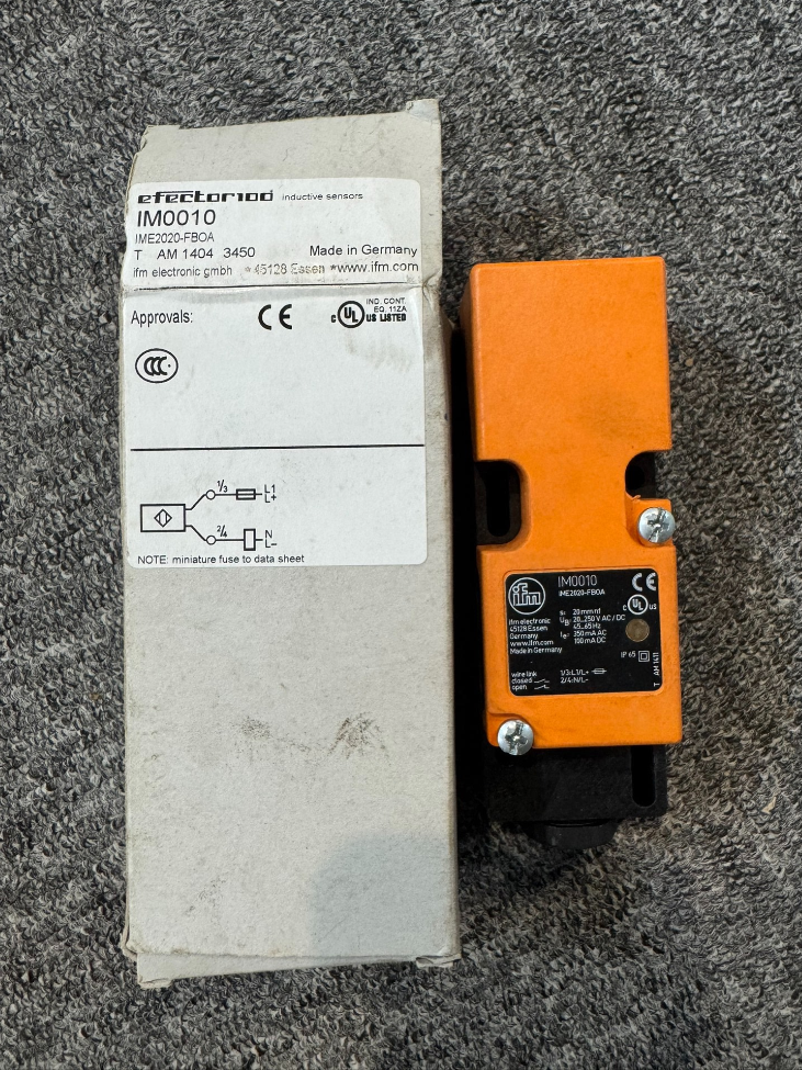

Grundlegende Informationen
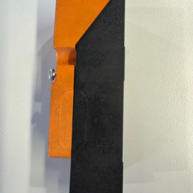
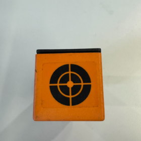
Typ: Rectangular inductive Näherungssensor (2-wire universal AC/DC)
Marke: ifm efector
Montage: Nicht bündig (ungeschirmt)
Rated real sensing distance Sr: 20 mm
Abmessungen: 40 × 40 × 121 mm
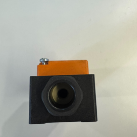
Verbindung: M20×1.5 cable gland, Schraubklemmenblock (max. 2.5 mm² Kabel)
Wichtige elektrische Spezifikationen
Betriebsspannung: 20…250 V AC/DC
Ausgabe: 2-Draht, selectable normally open (NEIN) / normalerweise geschlossen (NC)
Schaltfrequenz: 20 Hz (Wechselstrom) / 55 Hz (Gleichstrom)
Dauerlaststrom
Wechselstrom: 250 mA (bis zu 350 mA at ≤50 °C)
Gleichstrom: 100 mA
Mindestlaststrom: 5 mA (⚠️ Load current cannot be too low; otherwise the sensor fails to operate properly)
Spannungsabfall: ≤6.5 V (Wechselstrom); ≤6 V (Gleichstrom)
Leckstrom: <2.5 mA @ 250 VAC; <0.8 mA @ 24 VDC
Wichtiger Hinweis: No reverse polarity protection, no short-circuit protection. A ≤2 A fast-acting fuse is recommended upstream.
Umweltfreundlich & Mechanische Daten
Schutzklasse: IP65
Betriebstemperatur: -25 ℃ … +80 ℃
Gehäusematerial: PPE engineering plastic
Statusanzeige: Gelbe LED
Target material reduction factor: Steel=1|Stainless steel=0.7|Brass=0.4|Aluminum=0.3|Copper=0.2
Typische Anwendungen
Metal object detection on conveyors, limit positioning for heavy machinery, metal stop plate identification in warehousing & Logistik; ideal for sites with only AC220V power supply where DC24V is unavailable.
Verkabelungsrichtlinien
The 2-wire sensor must be wired in series with the load:
Macht L(+) → one sensor terminal → load → power N(-)
Do not short-circuit or energize without load; a minimum load of 5 mA is mandatory.
Comparison with Similar Models in the Series
| Modell | Erfassungsabstand | Montage | Gliederung | Unterschiede |
| IM0010 | 20 mm | Nicht bündig | 40×40×121 | Long housing, terminal connection |
| IM001A | 20 mm | Spülen | 40×40×105 | Permitted for embedded metal mounting |
| IM0011 | 20 mm | Nicht bündig | Short housing, plug connection | Connector-Version |
Selection Risk Warnings
- 2-wire AC/DC sensors not recommended to directly drive DC PLC inputs. Leakage current may trigger false signals; 4-wire PNP/NPN types are preferred.
- Absence of short-circuit protection; cable damage in field environment can easily burn out the sensor.
- Mindestlaststrom 5 mA; miniature relays and micro-indicator lamps may fail to draw sufficient operating current.
IFM IM0010 (IME2020-FBOA) Induktiver Näherungsschalter
Factors Affecting Sensing Distance (Nominal Sr = 20 mm)
The rated 20 mm is measured under standard test conditions: Baustahl, standard-size target, reference mounting distance. Effective distance decreases under actual operating conditions.
- Target Metal Material (Dominant Influence)
Reference baseline: Mild steel St37 = 100% (20 mm)
Reduction factors:
Edelstahl: ≈0.7 → Effective distance ≈14 mm
Messing: ≈0.4 → ≈8 mm
Aluminium: ≈0.3 → ≈6 mm
Kupfer: ≈0.2 → ≈4 mm
Intermittent detection of aluminum or copper workpieces commonly arises from severe reduction of effective sensing range.
- Größe & Thickness of Metal Target
IM0010 active sensing face: 40×40 mm
- Target dimensions smaller than active face → reduced sensing distance
- Steel plate thickness <1 mm prevents sufficient eddy current formation → distance attenuation
- Standard test target: 40×40×1 mm mild steel plate
- Sensor Mounting Layout (Critical for IM0010 – Non-flush Type)
IM0010 is an unshielded / non-flush sensor; NEVER install with metal tightly surrounding the housing.
- Metal brackets/housings adjacent to sensor sides and rear
→ Magnetic field is absorbed by metal, sensing distance reduced by 30%~60%, complete detection failure in severe cases
✅ Specification: Reserve ≥20 mm non-metallic clearance on all sides
- Multiple sensors mounted side-by-side
Mutual magnetic interference between adjacent unshielded inductive sensors causes false triggering and unstable detection range
✅ Minimum center-to-center spacing ≥3 × rated sensing distance ≈60 mm
- Betriebstemperatur
Betriebsbereich: -25 ℃ ~ +80 ℃
At high temperature (>60 ℃): Rising coil impedance weakens magnetic field and slightly reduces sensing distance
Low temperature generally imposes minor impact; sharp temperature fluctuations lead to switching point drift
- Supply Voltage Variation
IM0010 supply range: 20~250 V AC/DC
Low supply voltage weakens coil excitation magnetic field and slightly shortens effective sensing distance.
Avoid continuous operation near the lower limit of 20 V.
- Target Approach Angle & Parallelism
- Tilted metal plate entering sensing zone reduces effective detection distance
- Diagonal approach achieves shorter trigger distance compared to perpendicular head-on approach
Optimal condition: Target plate parallel and perpendicular towards the sensing face.
- External Electromagnetic Interference
Close parallel routing with cables for inverters, Schütze und Hochleistungsmotoren:
Alternating magnetic field disturbs the sensor oscillator circuit, presenting symptoms including:
Unstable detection range
No trigger at long distance, occasional loss of signal at short range
Verbesserung: Separate sensor wiring from power cables.
- Mechanical Contamination & Medium Conditions (IP65 rated)
- Ferrous dust/metal debris accumulated on sensing face acts as a premature metal target, causing advance triggering and sensitivity drift
- Water and oil contamination do NOT directly attenuate magnetic field (inductive sensors are unaffected by non-metallic media). Jedoch, oil sludge mixed with iron powder creates interference.
- Häufige Missverständnisse
✅ Non-metallic materials (Plastik, Gummi, timber, Wasser) do not affect sensing distance
❌ Many mistakenly believe oil contamination reduces range; pure oil creates no impact. Interference only occurs with mixed iron dust.
On-site Practical Recommendations Specific to IM0010
- For stainless steel, aluminum targets, design installation clearance with sufficient safety margin (60%~70% of nominal sensing distance).
- As an unshielded sensor, metal brackets cannot fit tightly alongside the housing; proper clearance is mandatory.
- Bei der Inbetriebnahme, measure actual trigger distance using real workpieces on site. Do not directly adopt the nominal 20 mm for mechanical layout.
General Installation Specifications for Unshielded (Nicht bündig) Inductive Proximity Sensors
Anwendbare Modelle: IFM IM0010, IM0011, IM001A and other rectangular unshielded inductive proximity sensors
Grundprinzip: Unshielded sensors have no metal shielding around the coil. Magnetic field radiates outward in all directions. Surrounding metal absorbs magnetic flux, shortening detection distance, causing false operation or complete failure.
- Minimum Clearance for Single Sensor Installation (Höchste Priorität)
Let Sr = rated sensing distance (Sr = 20 mm for IM0010)
- Front of sensing face: Reserved for target metal, this rule does not apply
- Metal adjacent to sensor sides (left/right/top/bottom): Minimum clearance ≥ 1 × Sr
- Metal behind sensor rear end: Minimum clearance ≥ 2 × Sr
👉 Practical values for IM0010:
Side clearance to metal ≥20 mm; rear clearance to metal ≥40 mm.
⚠️ Forbidden: Clamping the sensor inside metal slots or tight metal cutouts!
If fixation is required, use plastic brackets or non-metallic spacers for isolation.
Installation Cutout Prohibition
Unshielded sensors must NOT be embedded into metal panel cutouts. Embedding wraps the sensor with metal and short-circuits the magnetic field.
Only shielded (Unterputzmontage) sensors allow embedded metal installation.
- Side-by-Side / Opposite Mounting of Multiple Unshielded Sensors (Prevent Mutual Magnetic Interference)
- Side-by-side parallel installation (all sensing faces facing same direction)
Minimum center-to-center distance ≥ 3 × Sr
IM0010: ≥60 mm
- Opposite mounting (two sensing faces facing each other)
Minimum separation ≥ 4 × Sr
IM0010: ≥80 mm
- Staggered perpendicular layout
Minimum spacing ≥ 2 × Sr
Consequences of insufficient spacing: Fluctuating detection range, zufällige Fehlauslösung, detection only possible at close range.
- Specifications for Metal Targets
- Standardziel: Side length ≥ Sr, thickness ≥1 mm (Baustahl)
- Target smaller than sensing face → reduced effective range
- Thin plates, thin stainless steel and aluminum parts require extra safety margin
- Target should ideally approach parallel and perpendicular to sensing face; angled entry reduces trigger distance.
- Verkabelung & Verkabelungsspezifikationen
- Avoid routing sensor cables closely alongside high-current power cables (Wechselrichter, motor power lines). Maintain ≥30 cm separation; cross cables preferably at 90°.
- Prevent cables from prolonged high temperature, extrusion and abrasion.
- Do not wrap sensor cables around metal supports or hydraulic pipes.
- Umweltfreundlich & Mechanical Precautions
- Regularly clean ferrous powder accumulated on sensing face to avoid false signals
- Secure mounting under vibration conditions to prevent sensor displacement and trigger offset
- For IP65/IP67 sensors, water and oil on sensing face impose no negative impact (non-metallic media do not attenuate magnetic field).
- Shielded vs Unshielded Sensor Comparison (Auswahlreferenz)
| Artikel | Geschirmt (Unterputzmontage) | Ungeschirmt (Nicht bündig, z.B. IM0010) |
| Permitted embedded metal panel mounting | ✅ Allowed | ❌ Verboten |
| Allowing tight contact with side metal | ✅ Erlaubt | ❌ Clearance required |
| Maximum sensing distance within identical housing size | Kleiner | Größer (main advantage) |
| Sensitivity to interference | Niedrig | Hoch; strict installation clearance required |
- Standard Field Commissioning Procedure
- Install per minimum clearance requirements; remove redundant surrounding metal
- Measure actual trigger distance with real on-site workpieces, instead of relying on datasheet nominal Sr
- Set mechanical operating distance ≤70% of measured actual distance to reserve safety margin
- Observe yellow LED indicator during target movement to confirm no intermittent signal loss.
- Common Faults Originated from Improper Installation
- Detection only possible at short distance: Metal too close to sensor sides/rear
- Intermittent random false triggering: Insufficient spacing between adjacent sensors causing magnetic interference
- No detection signal at all: Sensor fully enclosed by metal leading to magnetic field short circuit





NH42-63-318x560.png "Automatische Transferschalter vom Typ CHINT PC (ATS)NH42-63/4SZ")



