 Schütz,Leistungsschalter,Sensor,Encoder,SPS,Konverter

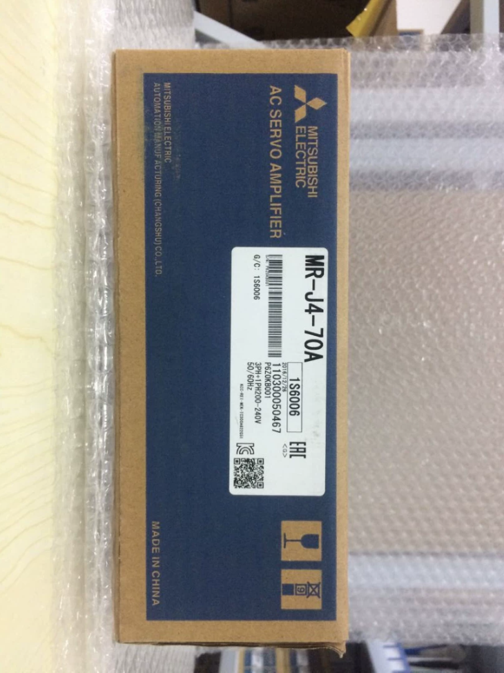

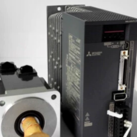
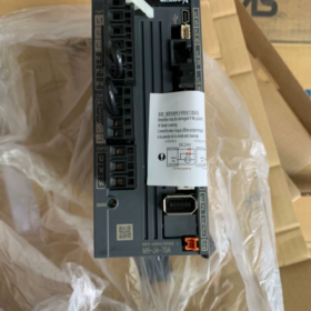
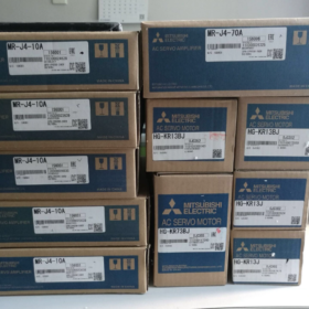
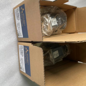
MELSERVO-J4-Serie, 750W (0.75 kW), 200-Universeller Impulseingang der V-Klasse Servoverstärker
Modelldefinition
MR-J4: Mitsubishi 4Servoserie der 20. Generation
70: Passende Motorleistung: 750 W
A: Universelle Schnittstelle (Impuls + analoger Eingang). Kein SSCNET-Glasfaserbustyp. Akzeptiert Impulsbefehle von SPS. Die Variante -B ist mit der Glasfaser-Busschnittstelle SSCNET III/H ausgestattet.
Grundlegende elektrische Spezifikationen
| Artikel | Spezifikation |
| Hauptstromkreis-Stromeingang | Einphasig / Dreiphasiger Wechselstrom 200-240 V, 50/60 Hz |
| Zulässiger Eingabebereich | AC170-264V |
| Nennausgangsstrom | 4.0 A; Spitzenstrom: 12 A (1 S) |
| Steuerstromversorgung | DC24V ±10 %, ca. 0.5 A |
| Steuermodi | Position (Max. Eingangsimpuls: 4 Mps), Geschwindigkeit, Drehmoment |
| Sicherheitsfunktion | STO (Sicher abgeschaltetes Drehmoment) |
| On-Board-Komponenten | Eingebauter regenerativer Widerstand, Dynamische Bremse |
| Konfigurationssoftware | MR-Konfigurator2, USB-Debug-Port |
Mechanische Spezifikationen
Abmessungen: B60×H168×T185mm
Gewicht: 1.4 kg
Montage: Vertikale DIN-Schienenmontage im Schrank, IP20
Betriebstemperatur: 0-55 °C, keine kondensation
Kompatible Motoren (Standardkombinationen)
HG-KR73: 750 W, geringe Trägheit, ohne Bremse
HG-KR73B: 750 W, geringe Trägheit, mit elektromagnetischer Bremse
HG-SR73: 750 W, mittlere Trägheit
Notiz: Verstärker und Motorgeber müssen aufeinander abgestimmt sein. MR-J4-Antriebe können Motoren der MR-J3-Serie nicht direkt betreiben.
Connector-Übersicht
- CN1: Digitale I/O-Signale, STO-Sicherheitseingänge
- CN2: Servomotor-Encoder-Schnittstelle
- CN3: Impuls / analoge Befehlseingabe (für Host-SPS)
- CN4: USB-Debug-Port für PC-Parameter-Setup
- CN5: Analoger Monitorausgang
- U/V/W: Leistungsabgabe an Servomotor
Ersatzkompatibilität
- Upgrade innerhalb derselben Produktfamilie
MR-J4-70A → MR-J5-70A (Impulsservo der neuen Generation). Die Hardware-Pinbelegung ist nicht kompatibel; Eine Neuabstimmung des Programms ist erforderlich.
- Ersatz für ältere Einheit
MR-J3-70A Nachrüstung: MR-J4-70A bietet funktionale Kompatibilität, Montageabmessungen und Verkabelung sind jedoch nicht vollständig austauschbar; Kabel müssen ausgetauscht werden.
- Vergleich der Bustypen
MR-J4-70A: Impuls / analoge Schnittstelle; MR-J4-70B: SSCNET-Glasfaserbus. Kein direkter Pin-für-Pin-Austausch.
Typische Anwendungen
Graviermaschinen, Etikettierer, Materialhandhabungsmechanismen, Verpackungsausrüstung, Vorschubachsen von Werkzeugmaschinen. Geeignet für SPS-Systeme mit Impulsausgabefähigkeit.
Fehlerbehebung & Wartungshinweise
- ALM32: Überstrom. Überprüfen Sie den U/V-W-Motor auf Kurzschluss oder Erdschluss.
- ALM50: Überlast. Auf mechanische Blockierung oder schlechte Trägheitsanpassung prüfen.
- AL.E6: Kommunikationsfehler des Encoders. Überprüfen Sie das CN2-Encoderkabel.
- Regenerative Überlastung: Häufiges schnelles Beschleunigen/Verzögern erfordert einen externen Bremswiderstand.
Zoll-HS-Code: 8501520000
Vollständige Installationsanleitung für Mitsubishi MR-J4-70A
⚠️Sicherheitswarnung: Sämtliche Verkabelungen und Demontagearbeiten müssen bei ausgeschalteter Stromversorgung durchgeführt werden. Warten Sie mindestens 15 Minuten, bis die Ladeanzeige erlischt. Stellen Sie sicher, dass zwischen P+-N keine Hochspannungsreste vorhanden sind- Klemmen mit Multimeter, um Stromschläge zu vermeiden. Die Arbeiten müssen von qualifizierten Elektrikern durchgeführt werden.
MR-J4-70A: 750 W, 200-Servoverstärker mit V-Impulseingang, Unterstützt einphasige oder dreiphasige AC200-240V-Versorgung.
- Mechanische Installation des Schranks
1.1 Installationsumgebung
Vertikal aufrecht im Schaltschrank montieren. NICHT flach hinlegen oder verkehrt herum installieren.
Umgebungstemperatur: 0-55 °C, keine kondensation; Höhe ≤1000m; Frei von Staub, Ölnebel und korrosives Gas.
Montagemethode: Schraubbefestigung oder DIN-Schienenmontage.
1.2 Kühlfreiräume (Kritisch)
Oberer Abstand ≥50 mm; Bodenfreiheit ≥50mm; Seitenabstand ≥10mm
Wenn mehrere Verstärker nebeneinander montiert sind, Reservieren Sie ausreichend Kühlraum. Von wärmeerzeugenden Bauteilen wie Schützen und Widerständen fernhalten.
Blockieren Sie die Einlass- und Auslassöffnungen nicht durch Kabel oder Kabelkanäle.
1.3 Befestigungsverfahren
- Stellen Sie sicher, dass die Rückplatte des Schranks flach und gratfrei ist.
- Setzen Sie den Verstärker gegen die Rückplatte und ziehen Sie die vier Befestigungsschrauben fest.
- Vermeiden Sie starke Stöße auf das Gehäuse, um Schäden an internen Komponenten zu vermeiden.
- Schritt-für-Schritt-Verkabelung
Anschlussdefinitionen für MR-J4-70A
L1, L2, L3: Leistungsaufnahme des Hauptstromkreises. Für einphasigen 220V-Betrieb: L1 anschließen & L2; Lassen Sie L3 unverbunden.
L11, L21: Steuerspannung AC200-240V
U/V/W: Leistungsabgabe an Servomotor
P+, N-: Klemmen für Rückspeisewiderstand; Werksseitige Kurzschlussbrücke für eingebauten Widerstand
PE: Schutzerde
CN1: Digitale I/O- und STO-Sicherheitssignale
CN2: Encoderstecker für HG-KR73 / HG-SR73-Motor
CN3: Impulsbefehls-E/A, verbunden mit SPS-Impulsausgang
CN4: Mini-USB-Debug-Anschluss für die PC-Software MR-Configurator2
Schritt 1: Schutzerde (PE)
Verbinden Sie den PE-Anschluss des Verstärkers und den PE-Anschluss des Motors mit der Schutzerdungsschiene des Schranks. Erdungswiderstand ≤10Ω. Führen Sie zunächst eine Erdung durch.
Schritt 2: Verkabelung des Stromkreises
- Hauptstromkreis L1/L2/L3
Dreiphasig AC200-240V: Draht L1, L2 und L3.
Einphasiger Wechselstrom 200–240 V: Verbinden Sie L1 und L2; L3 muss offen bleiben.
Leistungsschalter und Schütz vorschalten. Führen Sie niemals Netzspannung in die U/V-W-Ausgangsklemmen ein.
- Steuerstromkreis L11, L21: AC200-240V. Kann die Versorgung mit dem Hauptstromkreis teilen.
Notiz: Hauptstromkreis und Steuerstromkreis können getrennt versorgt werden. Für reines Signal-Debugging, Nur L11/L21 bestromen; Der Verstärker schaltet sich ohne Hauptmotorspannung ein.
- Konfiguration des Rückgewinnungswiderstands:
Normaler Start-Stopp-Betrieb: Behalten Sie die werkseitige Kurzschlussbrücke zwischen P+-D bei, um den internen Bremswiderstand zu verwenden.
Häufiges schnelles Beschleunigen/Verzögern: Entfernen Sie die Brücke und installieren Sie einen externen Bremswiderstand zwischen P+ und N-., Wählen Sie den richtigen Widerstand und die richtige Nennleistung.
Schritt 3: Motorstromkabel U/V/W
Verstärker U-Motor U anschließen; V-Motor V; W-Motor W eins zu eins. Phasen NICHT vertauschen. Schütz nicht einstecken, Kondensator oder Überspannungsschutz zwischen Verstärker und Motor.
Motoren mit elektromagnetischer Bremse: Die Bremsspule erfordert eine unabhängige 24-V-Gleichstromversorgung. Die Bremsfreigabelogik muss über ein externes Relais gesteuert werden. Betätigen Sie die Bremskraft nicht über den Servoantrieb.
Schritt 4: Encoderkabel CN2
Verwenden Sie ein spezielles MR-J4-Encoderkabel. Stecken Sie den CN2-Stecker vollständig ein und verriegeln Sie ihn. Verlegen Sie das Encoderkabel weg von den Stromkabeln. Vermeiden Sie scharfes Biegen oder Ziehen. MR-J3-Encoderkabel sind NICHT mit MR-J4-Antrieben kompatibel.
Schritt 5: Digitaler E/A CN1 & Impulsschnittstelle CN3 (Positionsimpulssteuerung)
- EM2 (Zwangsstopp / Nothalt): Hardware-Sicherheitssignal. Fest verdrahteter Not-Aus-Schalter für betriebsbereite Maschinen. Kurzschluss nur für vorübergehende Prüfstandstests.
- SOHN (Servo-Ein), RES (Alarm-Reset), LSP (Vorwärtshubbegrenzung), LSN (Rückwärtshubbegrenzung).
- CN3-Impulsbefehl: Wählen Sie das Format PULSE+SIGN entsprechend der SPS-Ausgangskonfiguration.
Halten Sie einen Abstand von ≥10 cm zwischen Signalkabeln und Stromkabeln ein, um Störgeräusche zu reduzieren. Verwenden Sie geschirmte Signalkabel mit einseitiger Schirmerdung.
Schritt 6: Debug-Schnittstelle CN4-USB
Schließen Sie das Mini-USB-Kabel zwischen PC und CN4 an. Installieren Sie die MR-Configurator2-Software zur Parametersicherung, JOG-Betrieb und Alarmdiagnose.
- Obligatorische Checkliste vor dem Einschalten (Bei ausgeschaltetem Gerät durchführen)
- Multimetermessungen:
Kein Kurzschluss zwischen L1-L2-L3 und L11-L21.
Gute Isolierung; Kein Kurzschluss Phase-Phase oder Phase-Erde am U/V-W-Motorausgang.
Kein Kurzschluss zwischen P+ und N- Terminals.
- Überprüfung der Verkabelung:
Stellen Sie sicher, dass die Netzversorgung NICHT an die U/V-W-Ausgangsklemmen angeschlossen ist.
U/V-W-Phasen korrekt aufeinander abgestimmt; Geberstecker verriegelt; PE-Erdungskörper.
Jumper für den Rückgewinnungswiderstand / externer Widerstand korrekt montiert; Bremsverkabelung überprüft.
- Mechanische Inspektion:
Kupplung fest angezogen; keine mechanische Bindung; keine mechanische Kollisionsgefahr. Implementieren Sie einen Absturzschutz für vertikale Achsen.
- Sicherheitsschlaufe: Funktionsfähigkeit des Not-Aus-Schaltkreises bestätigt.
- Einschaltsequenz
- Halten Sie das Personal von beweglichen Mechanismen fern; Positionieren Sie die Maschine an einem sicheren Ort.
- Schalten Sie zuerst die Steuerspannung L11/L21 ein. Bestätigen Sie, dass sich der Verstärker ohne Alarme einschaltet.
- Hauptstromkreis L1/L2/L3 schließen.
- Wenn Alarme auftreten: Fehlerbehebung anhand von Alarmcodes (AL32 Überstrom, AL.E6 Encoderfehler, AL50-Überlastung).
- PC-Software anschließen und Werksparametersatz sichern.
- Debug-Workflow:
- Führen Sie JOG mit niedriger Geschwindigkeit über die Software aus, Überprüfen Sie die Drehrichtung des Motors.
- Weiterleitung validieren / Rückwärtsbegrenzungssignale.
- Konfigurieren Sie das Impulsformat und das elektronische Übersetzungsverhältnis passend zur SPS.
- Testen Sie die Positionierung mit kleinvolumigen Impulsbefehlen; Reisen schrittweise steigern.
- Führen Sie einen vollständigen Bewegungszyklus aus und führen Sie One-Touch-Tuning zur Optimierung der Servoverstärkung durch.
- Häufige Fallstricke bei der Installation
- Einphasige Versorgung: Schließen Sie keine Spannung an die Klemme L3 an.
- Das Anlegen einer Wechselstromspannung von 220 V an U/V-W führt zur dauerhaften Zerstörung des Verstärkers.
- Ein lockerer CN2-Stecker des Encoders verursacht einen zeitweiligen Encoderfehler AL.E6.
- Die direkte Stromversorgung der Motorbremse über den Servoantrieb führt zu einem Fehler beim Lösen der Bremse.
- Unzureichender Kühlfreiraum führt im Dauerbetrieb zum Thermoalarm AL51.
- Wenn der Not-Aus-Schalter EM2 unverkabelt bleibt, wird der Servo-Ein-Betrieb verhindert.
- Die parallele Verlegung von Strom- und Signalkabeln führt zu Impulsrauschen und Positionierungsverlusten.
- Wartung
Ziehen Sie die Klemmschrauben regelmäßig nach; Halten Sie den Schrank staubfrei. Servoparameterdateien jährlich exportieren und speichern.
Lagerbedingungen: -20 ~+65°C, keine kondensation.
Komplettes Parameter-Tuning-Verfahren für Mitsubishi MR-J4-70A
MR-J4-70A Servoverstärker mit Impulseingang. Tuning-Tool: MR-Konfigurator2 (Mini-USB-Kabel an CN4 angeschlossen).
⚠️Vor dem Tuning: Stellen Sie sicher, dass die Maschine mechanisch frei von Blockaden ist; Halten Sie das Personal von beweglichen Teilen fern. Nach Parameteränderung, Schreiben Sie Parameter zur nichtflüchtigen Speicherung in das EEPROM. Parametergruppen: PA-Grundparameter, PB-Gewinn & Filter, PC-Extended-Parameter, PD-I/O-Zuweisungsparameter.
- Softwareverbindung & Vorbereitungen
- Schließen Sie den Mini-USB-Anschluss des PCs an CN4 an. Laufwerk einschalten. Starten Sie MR-Configurator2, gehen Sie online, Lesen Sie alle Parameter und speichern Sie die Parametersicherungsdatei.
- Werksreset (optional): Schreibschutz über PA19 aufheben, Parameter-Reset durchführen, Schalten Sie das Gerät aus und wieder ein, damit die Änderungen wirksam werden.
- Bestätigen Sie die Motoridentifikation: Überprüfen Sie den angeschlossenen Motor HG-KR73 / HG-SR73 wird im Software-Monitorbildschirm korrekt erkannt; kein Motor-Mismatch-Alarm.
- Grundlegende Steuerparameter (Am häufigsten verwendeter Positionsimpulsmodus)
PA-Gruppe (Grundlegende Einstellungsparameter)
| Parameter-Nr. | Name | Beschreibung | Typische Einstellung |
| PA01 | Auswahl des Betriebsmodus | 1000 = Pulspositionskontrolle; 0001 = Geschwindigkeit; 0002 = Drehmoment | 1000 (Pulspositionierung) |
| PA13 | PLSS-Befehlsimpuls-Eingangsformat | Passen Sie das SPS-Impulsausgabeformat an | Muss mit der SPS-Konfiguration übereinstimmen |
| 0100: IMPULS+ZEICHEN (Impuls + Zeichen, am häufigsten) | |||
| 0001: CW/CCW-Doppelimpuls | |||
| 0002: A/B-Phasen-Quadraturimpuls | |||
| PA06 CMX | Elektronischer Getriebezähler | CDVCMX=Anzahl der SPS-Impulse pro Motor RevolutionMotor-Encoder-Auflösung(4194304) | Berechnet pro mechanischem Aufbau |
| PA07 CDV | Nenner des elektronischen Getriebes | ||
| PA10 | INP In-Position-Bereich | Ausgabefenster „Position abgeschlossen“., Einheit: Befehlsimpulse | 50-200, Passen Sie es an die Genauigkeitsanforderungen an |
| PA11 | Befehlsimpulsfilter | 0 für differenziellen Leitungstreibereingang; für Open-Collector-Eingang auf 1 gesetzt | 0 (Differenzsignal) |
| PA19 | Parameterschreibsperre | 0000: Vollständige Parameteränderung zulässig; Aktivieren Sie nach der Inbetriebnahme die Schreibsperre | 0000 während des Debuggens |
✅Beispiel für ein elektronisches Getriebe: Kugelgewindesteigung 10 mm, direkte Motorkopplung. Erfordern 10000 SPS-Impulse pro voller Motorumdrehung.
Encoder-Auflösung: 4194304 (22-bisschen)
CMX/CDV = 4194304 / 10000 → CMX=4194304, CDV=10000
Hardware-Hinweis: Differenzeingang max. 4 Mpps; Open-Collector max. 200 kpps. Verwenden Sie für den Hochgeschwindigkeitsbetrieb die Differenzsignalisierung.
- Digitale I/O-Parameter der PD-Gruppe
- PD01-PD14: Belegung der Eingangsklemmen (CN1)
SOHN (Servo-Ein), LSP (Vorwärtshubbegrenzung), LSN (Rückwärtshubbegrenzung), RES (Zurücksetzen), EM2 (Nothalt).
Der Hardware-Not-Aus-Schalter EM2 muss fest verdrahtet sein. Kurzschlussverbindung nur für temporäre Prüfstandstests zulässig; niemals für Produktionsanlagen.
- PD20-PD27: Belegung der Ausgangsklemmen: ALM (Alarm), RD (Servobereit), INP (In-Position abgeschlossen).
- Einschalten & Rechtsorgan (SPS-Anbindung nicht erforderlich, Motorvalidierung zuerst)
- Software → Testbetrieb → JOG-Betrieb.
- Stellen Sie eine niedrige Geschwindigkeit von 50–200 U/min ein, vorwärts und rückwärts joggen.
- Drehrichtung bestätigen. Wenn die Richtung umgekehrt ist: Einstellung von PA14 Drehrichtungsauswahl umkehren.
- Auf ungewöhnliche Geräusche prüfen, Vibration und mechanische Bindung.
Führen Sie die JOG-Validierung durch, bevor Sie SPS-Impulsbefehle anschließen.
- Servo-Gain-Tuning (Kritisch für Vibrationen, Überschwingzeit und Positionierzeit)
Drei Tuning-Methoden für MR-J4: One-Touch-Tuning (Empfohlene erste Wahl), Autotuning in Echtzeit, Manuelle Feinabstimmung der PB-Parameter.
Methode1: One-Touch-Tuning (Empfohlen für die Inbetriebnahme)
- Komplette mechanische Baugruppe mit montierter realer Last.
- Software-Menü Tuning → One-Touch-Tuning.
- Zielreaktionsniveau festlegen: 1-15
Leichtlastmaschine mit hoher Steifigkeit: 8-12
Zahnriemen / Mechanismus mit geringer Steifigkeit: 3-7
- Verfahren ausführen; Der Servo führt eine hin- und hergehende Testbewegung aus, um die Lastträgheit abzuschätzen und Verstärkungen und Filter automatisch einzustellen.
- Schreiben Sie das Ergebnis nach Abschluss in das EEPROM.
- Positionierzyklen durchführen; Schwingungen bewerten, Überschwingen und akustische Geräusche.
Methode2: Autotuning in Echtzeit
Stellen Sie den PA08-Tuning-Modus auf „_ _ _1“ ein. Der Servo schätzt kontinuierlich die Lastträgheit und passt die Verstärkung während des tatsächlichen Maschinenbetriebs dynamisch an. Geeignet für wechselnde Lastbedingungen.
Methode3: Manuelle Feinabstimmung der PB-Parameter (Verfeinern Sie, wenn das One-Touch-Ergebnis nicht zufriedenstellend ist)
| Parameter | Name | Funktion |
| PB06 | Trägheitsverhältnis zwischen Last und Motor | Lastträgheit / Trägheitsmotor. Automatisch berechnet durch One-Touch-Tuning; können manuell eingegeben werden. |
| PB07 | Positionsregelkreisverstärkung PG1 | Höhere Werte beschleunigen die Positionierung; Eine übermäßige Verstärkung führt zu Schwingungen |
| PB08 | Geschwindigkeitsregelkreisverstärkung VG1 | Bestimmt die dynamische Reaktion; Höher verbessert die Tracking-Leistung |
| PB09 | Integralzeit des Geschwindigkeitsregelkreises VI | Ein kleinerer Wert stärkt das ganzheitliche Handeln, erhöht die Schwingungsneigung |
| PB13 | Tiefpassfilter | Unterdrücken Sie hochfrequente mechanische Resonanz |
| PB01 | Adaptiver Vibrationsunterdrückungsfilter | Set1, um die automatische Resonanzunterdrückung zu aktivieren |
Manuelle Tuning-Sequenz: Stellen Sie zunächst die Parameter des Geschwindigkeitsregelkreises ein, dann Positionsschleife. Wenn Schwingungen auftreten, Verstärkungswerte sofort reduzieren; Erhöhen Sie den Gewinn nicht blind.
Symptombasierte Korrekturtabelle
- Summende Vibration im Stillstand: Reduzieren Sie die Positionsregelkreisverstärkung PB07; Aktivieren Sie den adaptiven Filter PB01, Kerbfilter konfigurieren.
- Positionsüberschreitung: Geringere Positionsregelkreisverstärkung; Erhöhen Sie die Integralzeit des Geschwindigkeitsregelkreises.
- Langsame Reaktion und lange Einschwingzeit: Erhöhen Sie PG1 und VG1 moderat.
- Anormales Geräusch mit fester Frequenz: Verwenden Sie die Machine-Analyzer-Funktion der Software, um die Resonanzfrequenz zu scannen und den Kerbfilter zu konfigurieren.
- Limit, Heimkehr & Drehmomentgrenzparameter
- PA12 Drehmomentgrenze: Bereich 0-100 %. Bei der Inbetriebnahme auf 50 % einstellen, um mechanische Kollisionsschäden zu verhindern.
- PC01-PC06: Referenzierungsparameter; Home-Return-Modus, Referenzgeschwindigkeit, Kriechgeschwindigkeit, Home-Offset-Wert.
- PC13, PC14: Soft-Limit-Positionsschwellenwerte (Einheit: Befehlsimpulse).
- Parameter-Upload / Herunterladen & Sparen
- Nach der Änderung, Führen Sie „Write to EEPROM“ in der Software aus. Nur im RAM gespeicherte Änderungen gehen beim Aus- und Wiedereinschalten verloren.
- Hochladen: Servoparameter lesen und Projektdatei speichern. Zum Austausch des Verstärkers, Laden Sie die gespeicherte Parameterdatei für eine schnelle Inbetriebnahme herunter.
- Standard-Testsequenz für die Inbetriebnahme
- JOG-Anwaltskörperschaft; Bestätigen Sie die Drehrichtung und keine mechanische Blockierung.
- Senden Sie Impulsbefehle mit kleinem Volumen von der SPS, Überprüfen Sie die zurückgelegte Strecke mithilfe der Berechnung des elektronischen Übersetzungsverhältnisses.
- Hin- und Herbewegung mit niedriger Geschwindigkeit; auf Geräusche und Vibrationen prüfen.
- Führen Sie One-Touch-Tuning aus.
- Positionierungszyklen mit mittlerer und voller Geschwindigkeit; Überwachen Sie den In-Position-Status, Überschwingen und Restschwingungen.
- Funktionsprüfung der Hubbegrenzungen, Not-Aus und Alarm-Reset.
- Nach vollständiger Validierung, Speichern Sie die vollständige Parametersicherung.
- Häufige Fehler bei der Inbetriebnahme
- Motor dreht sich nicht, RD (Servobereit) Ausgang EIN: Überprüfen Sie SOHN (Servo-Ein) Signal, Not-Aus-Schleife EM2 und Betriebsarteneinstellung PA01.
- Motor dreht sich, aber der Verfahrweg ist falsch: Überprüfen Sie das PA13-Impulseingangsformat und die Berechnung des elektronischen Übersetzungsverhältnisses CMX/CDV.
- Vibrationen und ungewöhnliche Geräusche während des Betriebs: Falsche Einstellung des Trägheitsverhältnisses, übermäßiger Gewinn, mechanische Resonanz. Priorisieren Sie One-Touch-Tuning plus Machine-Analyzer-Tool.
- AL50 Überlastalarm: Übermäßiges Last-Trägheits-Verhältnis, hohe mechanische Reibung, Verstärkungswerte zu hoch.
- AL.E6 Encoder-Alarm: Beschädigtes oder schlecht sitzendes CN2-Encoderkabel.
HS-Code für den Zoll: 8501520000





NH42-63-318x560.png "Automatische Transferschalter vom Typ CHINT PC (ATS)NH42-63/4SZ")



