 Schütz,Leistungsschalter,Sensor,Encoder,SPS,Konverter

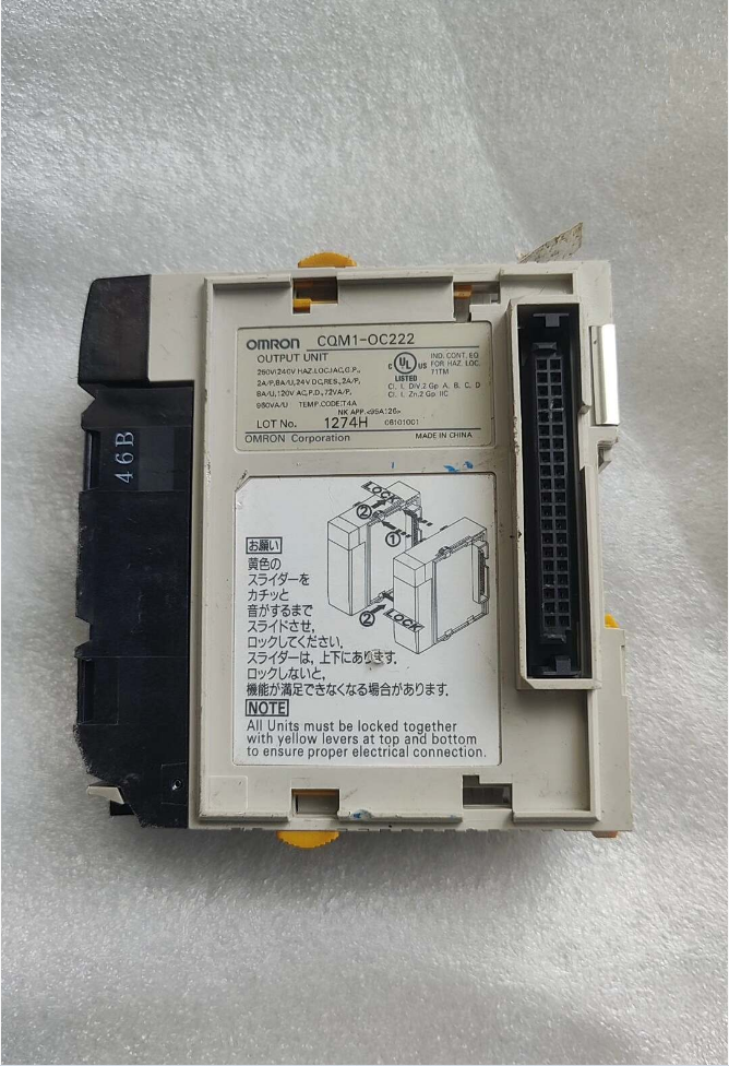

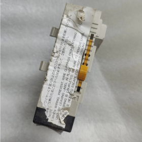
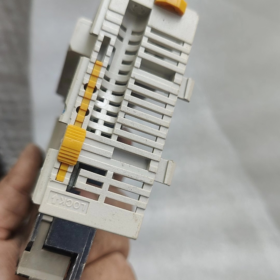
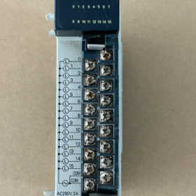
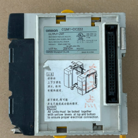
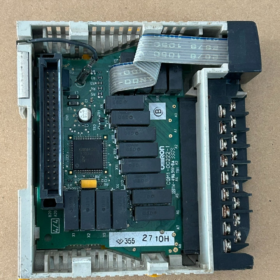
OMRON CQM1-OC222 Installationsanweisungen
⚠️Sicherheitsvoraussetzung: Führen Sie alle Installationsarbeiten bei vollständig ausgeschalteter Stromversorgung durch. Schalten Sie das SPS-System und die externe Laststromversorgung aus. Der Austausch von Modulen im laufenden Betrieb ist verboten.
Dies ist eine E/A-Einheit der CQM1/CQM1H-Serie und funktioniert nur auf CQM1H-Backplane-Racks. Nicht kompatibel mit Racks der CJ-Serie oder CP-Serie.
Serie: CQM1 / CQM1H-Relais Ausgangsmodul, Veraltet, Es sind nur Gebraucht- oder Lagergeräte verfügbar.
Typ: Relaiskontaktausgang, 16 Punkte, 2 gemeinsame Gruppen, 8 Punkte pro Gruppe (COM1: Punkte 0-7; COM2: Punkte 8-15).
Kernspezifikationen
| Artikel | Parameter |
| Anzahl der Ausgabepunkte | 16-Punkt-Relaisausgang, 8 Punkte pro COM, 2 Schaltkreise |
| Lastspannung | AC250V; DC24V |
| Strom pro Punkt | 2A für ohmsche Last; 0.5A für induktive Last |
| Max. Aktuell pro COM-Gruppe | 4A (insgesamt für 8 Punkte); Max. 8A für das gesamte Modul |
| Ausgabeantwort | EIN ca. 10 MS; AUS ca. 10 MS (mechanische Verzögerung des Relais) |
| Isolierung | Opto-Isolierung des Relais |
| Adresse | Besetzt 1 I/O-Kanal (16 bisschen) |
| Stromverbrauch der Rückwandplatine | 5VDC: 130 mA |
| Terminals | M3-Schraubklemmenblock |
>⚠️Hinweis: Alle Punkte innerhalb einer COM-Gruppe müssen die gleiche externe Stromversorgung nutzen. COM1 und COM2 können unterschiedliche Spannungen verwenden. Eine unabhängige Stromversorgung für jeden einzelnen Punkt ist nicht zulässig. Dies unterscheidet sich von CQM1-OC221 (8-Punktunabhängiges COM).
Modelldekodierung
CQM1: SPS-E/A-Einheit der CQM1-Serie
OK: Relaiskontaktausgang
222: 16 Punkte, 2 Gemeinsamer Gruppen-Relaisausgang
Vergleich mit Peer-Series-Modulen:
CQM1-OC221: 8 Punkte, unabhängiger gemeinsamer Anschluss für jeden Punkt, Geeignet für Lasten mit unterschiedlichen Spannungen pro Kanal
CQM1-OC222: 16 Punkte, 2 gemeinsame Terminals, höhere Punktdichte, gemeinsame Stromversorgung innerhalb jeder Gruppe
CQM1-OC224: Unabhängige 8-Punkt-COM-Einheit der neuen Version
Verkabelungsrichtlinien
- COM1 verbindet sich mit der gemeinsamen externen Stromversorgung für Ausgänge 0-7; COM2 verbindet sich mit der gemeinsamen externen Stromversorgung für Ausgänge 8-15.
- Relaisausgänge sind Trockenkontakte. Das Modul liefert keine Ausgangsleistung; Die Lasten müssen mit externer Energie versorgt werden.
- Für induktive Lasten (Schützspulen), RC-Überspannungsschutzschaltung installieren / Freilaufdiode zur Verlängerung der Lebensdauer der Relaiskontakte.
- Anzugsdrehmoment der Klemmen: 0.5 N·m.
Ersatzoptionen
Direkte Kompatibilität mit der CQM1H-Backplane (Direkter Hardware-Austausch)
CQM1-OC222 wird nicht mehr hergestellt. Kein natives 16-Punkt-2-COM-Relaismodul in derselben Serie.
Zwei Stück CQM1-OC221: Gesamt 16 Punkte, aber größerer Platzbedarf, 8-Punktunabhängiges COM.
Upgrade auf die CJ-Serie (Rückwandplatine nicht kompatibel; Vollständiges SPS-Upgrade erforderlich)
CJ1W-OC211: 16-Punktrelaisausgang, 2 COM-Gruppen (8 Punkte pro COM). Nächstes elektrisches Äquivalent zu CQM1-OC222. Die Programmlogik ist portierbar, Es erfordert jedoch eine CJ1/CJ2-Rückwandplatine und kann nicht direkt an das CQM1H-Rack angeschlossen werden.
Inländisches Ersatzkonzept
Ersetzen Sie die gesamte SPS durch Inovance H3U / H5U, gepaart mit AM600-0016ER (16-Punktrelaisausgang, 2 gemeinsame Terminals).
Checkliste für die Inspektion gebrauchter Module für CQM1-OC222
- Visuelle Kontrolle: Backplane-Stecker ohne Abbrand, Reihenklemmen ohne Lichtbogenschwärzung, Keine Korrosion am Gehäuse.
- Einschalttest: Insert into CQM1H rack; confirm module is recognized without I/O errors.
- Forced-output via software: Force each point ON using CX-Programmer and observe panel LEDs. LED ON ≠ intact contact. (Healthy internal drive does not guarantee good relay contacts, a frequent failure for second-hand units.)
- Multimeter measurement: Measure continuity between output terminal and corresponding COM while forcing ON; verify infinite resistance in OFF state. Test all 16 points one-by-one.
- Typical failure modes:
LED ON but no continuity: Relay contact erosion (most common second-hand fault)
Total failure of 8-point group: Over-current burnout of COM circuit
Individual-point sticking: Output remains conductive even under OFF command
Common Troubleshooting Hints
- Relay mechanical service life is limited. Frequent switching of inductive loads accelerates contact erosion, sticking and poor contact.
- The module does not supply output power. Missing external load power may mimic “no output action”. Always check external power supply at COM terminals first.
- CQM1H CPUs all support CQM1-OC222. No CPU-version compatibility issue.
- Anforderungen an die Installationsumgebung
- Umgebungstemperatur: 0 ~ 50 ℃. Ensure adequate ventilation inside control cabinet. Do not mount close to heaters or frequency converters.
- Luftfeuchtigkeit: 10%-85%RH, keine kondensation. Von Staub fernhalten, corrosive gas and oil mist.
- Avoid heavy vibration and strong electromagnetic interference sources (Schütze, high-power inverters).
- Mount horizontally; do not install upside-down.
- Mounting Modules on Rack (Unit Assembly)
- Confirm PLC system is fully powered off.
- Align the left-side backplane connector of CQM1-OC222 with the right-side backplane interface of preceding unit (CPU, power supply or other I/O modules).
- Richten Sie die Module aus und drücken Sie sie horizontal, bis die Einheiten fest sitzen. Schieben Sie die oberen und unteren Verriegelungsriegel ganz nach hinten, um benachbarte Einheiten zu verriegeln und einen zuverlässigen Backplane-Kontakt zu gewährleisten.
- Installieren Sie die Endabdeckung am äußersten rechten Ende des gesamten Systems und verriegeln Sie die Riegel. Eine fehlende Endabdeckung führt zu Fehlern bei der E/A-Erkennung.
- Montieren Sie die komplette SPS-Baugruppe (Stromversorgung + CPU + I/O-Module) auf DIN35-Schiene: Drücken Sie den DIN-Clip auf der Rückseite des Moduls, um ihn auf der Schiene einzurasten. Zum Entfernen den Clip lösen.
Notiz: Die physische Steckplatzposition bestimmt die E/A-Kanaladresse. Keine DIP-Schalter am Modul; Adressen werden automatisch nach Steckplatzstandort zugewiesen.
- Entfernen des Klemmenblocks & Beschlag (Abnehmbarer Klemmenblock)
CQM1-OC222 verfügt über einen abnehmbaren M3-Schraubklemmenblock für eine bequeme Offline-Verkabelung und einen Modulaustausch, ohne dass Feldkabel entfernt werden müssen.
- Klemmenblock entfernen: Pinch both side clips and pull straight out while module stays on rack.
- Nach der Verkabelung, align and push terminal block back into slot until both side clips click into locked position.
❗Do not pry forcibly to prevent clip breakage.
- Wiring Procedures & Spezifikationen
Klemmendrehmoment
M3-Schraube, tightening torque 0.45-0.5 N·m. Over-torque damages threads; insufficient torque creates thermal loose-connection risks.
Leitergröße: 0.3-0.75 mm² (AWG22-18). Use solid wire or stranded wire with ferrules. Prevent stray copper strands from causing short-circuits.
Output Circuit Wiring Logic (Kritisch)
- COM1 terminal: Common for points 0-7; COM2 terminal: Common for points 8-15.
- This module provides relay dry contacts with no internal power source. Feed external power to COM terminals and connect loads to output-point terminals.
- COM1 and COM2 may accept different voltages (z.B. one group AC220V, another DC24V). Do NOT mix AC and DC within one COM group.
- Für induktive Lasten (Schütze, Magnetventile): Bei Wechselstromlasten RC-Snubber anwenden; Rückwärtsparallele Freilaufdiode für Gleichstromlasten zum Schutz der Relaiskontakte.
Verdrahtungsreihenfolge
- Verdrahten Sie zuerst die Feldlaststromkreise, Schließen Sie dann die gemeinsame COM-Stromversorgung an.
- Komplette Verkabelung, auf Kurzschlüsse und freiliegende Kupferlitzen prüfen.
- Stellen Sie sicher, dass der Klemmenblock wieder vollständig am Modul eingerastet ist.
- Einschalten & Hardware-Verifizierung
- Überprüfen Sie noch einmal, ob die SPS-Stromversorgung und die externe Laststromversorgung ausgeschaltet sind; Vergewissern Sie sich, dass die rechte Endabdeckung angebracht ist.
- Schalten Sie die Stromversorgung des SPS-Systems ein und versorgen Sie die CPU mit Strom. Modulanzeigen beachten:
Unter normalen Bedingungen gibt es an diesem Modul keine spezielle Fehler-LED. Ausgangs-LEDs folgen dem internen Ausgangsstatus.
- Gehen Sie online über CX-Programmer. Bestätigen Sie, dass die CPU die E/A-Einheit erkennt und keinen E/A-Einheitsfehler meldet.
- Erzwingen Sie das Ein-/Ausschalten jedes Ausgangspunkts in der Software. Beobachten Sie den LED-Status und überprüfen Sie den Anschlussdurchgang mit einem Multimeter, um die Ausgänge zu validieren.
- Modulaustausch & Entfernungsverfahren (Wartung)
- Power off PLC and cut external load power.
- Pull out removable terminal block (field wiring may remain on terminal block without disassembly).
- Unlock locking latches between this module and adjacent units.
- Gently pull module outward to disengage backplane connector and release from DIN rail.
- Install new module following above installation steps and re-insert terminal block.
- Häufige Installationsfehler & Resulting Faults
- Missing right-hand End Cover: CPU fails to detect module; I/O error reported.
- Locking latches not fully engaged: Schlechter Backplane-Kontakt; intermittent module dropout.
- Reversed COM-to-output-point wiring: Load inaction; mixed-voltage within one COM group → internal relay damage.
- Improper terminal screw torque: Overheating and arcing at terminals during operation.
- Hot-swap under power: Permanent burnout of backplane and module.
OMRON CQM1-OC222 Fehlerdiagnoseverfahren
Für Einheiten mit Relaiskontaktausgang: Das Einschalten der LED garantiert NICHT intakte Relaiskontakte. Der interne Antriebsschaltkreis kann normal funktionieren, während die mechanischen Relaiskontakte erodiert sind oder festsitzen (Fehler mit hoher Wahrscheinlichkeit).
Vor dem Testen: Schalten Sie die SPS aus und trennen Sie die externe Stromversorgung von den Modulklemmen, um Störungen durch die Feldverkabelung zu vermeiden.
- Visuelle Inspektion (Ausgeschalteter Zustand)
- Backplane-Anschluss: Auf Brandflecken prüfen, Korrosion, verbogene oder beschädigte Stifte.
- Verdrahtungsklemmen: Auf Lichtbogenschwärzung prüfen, Brandflecken oder geschmolzenes Plastik.
- Gehäuse: Auf Risse prüfen, Brandschäden und verbrannter Geruch.
Brandflecken oder verbrannter Geruch weisen in der Regel auf einen dauerhaften Hardwareschaden hin.
- Rackmontiertes Einschalten & Software-Identifikationstest
Montieren Sie das Modul mit montierter Endabdeckung in das CQM1/CQM1H-Rack. Schalten Sie den CX-Programmer ein und schließen Sie ihn an.
- Überprüfen Sie, ob die Hardwareliste CQM1-OC222 korrekt identifiziert.
- Überprüfen Sie, ob ein I/O-Einheitsfehler vorliegt / Ungewöhnliche Alarme des Geräts.
✅Normal: Richtige Identifizierung, keine Alarme. Backplane-Schnittstelle, Die Bordstrom- und Decodierungsschaltkreise sind grundsätzlich funktionsfähig.
❌Fehler: Modul nicht erkannt / Gerätefehleralarm:
Überprüfen Sie die Endabdeckung und die Verriegelungsriegel noch einmal.
Testmodul im alternativen Steckplatz; Kreuztest mit bekanntermaßen gutem Modul.
Wenn der Fehler weiterhin besteht: Schäden an der Hauptplatine an Bord.
⚠️Eine erfolgreiche Erkennung beweist lediglich die Integrität der Leiterplatte. Es ist KEINE Garantie für einwandfreie Relaiskontakte. Viele defekte Module werden korrekt erkannt, weisen aber schlechte Einzelpunktkontakte auf.
- LED-Anzeigetest (Software-erzwungene Ausgabe)
Gehen Sie online, Ausgänge EIN/AUS erzwingen und Panel-LEDs beobachten:
- Die LED leuchtet beim FORCE-ON auf und erlischt beim FORCE-OFF.
LED folgt Befehl: Die interne Treibertransistorschaltung funktioniert.
LED leuchtet nicht: Fehler im internen Treiberschaltkreis für diesen Kanal.
Wichtig: Eine leuchtende LED bedeutet nur, dass das interne Laufwerk aktiviert ist. Es garantiert NICHT die Leitung des Relaiskontakts! Die Messung am Multimeter-Terminal ist obligatorisch.
- Multimetertest von Relaiskontakten (Obligatorischer Schlüsselschritt)
Trennen Sie alle externen Feldverkabelungen. Stellen Sie das Multimeter auf Durchgangston ein / Widerstandsmodus.
Terminalzuordnung: COM1 für Punkte 0-7; COM2 für Punkte 8-15.
Testschritte
- Force-Punkt in der Software EIN: Messen Sie den Widerstand zwischen dem Ausgangsanschluss und dem entsprechenden COM-Anschluss.
✅Normal: Widerstand nahe Null, Kontinuitätston.
❌Fehler: Unendlicher Widerstand / kein Durchgang → Erosion der Relaiskontakte (häufigster Ausfall).
- Force Point OFF in der Software: Messen Sie den Widerstand zwischen dem Ausgangsanschluss und dem entsprechenden COM-Anschluss.
✅Normal: Unendlicher Widerstand, keine Kontinuität.
❌Fehler: Immer noch leitend → Relaiskontakt klemmt, unkontrollierte Belastung (gefährlicher Fehler).
Test all 16 points one-by-one. Oft nur 1-2 Punkte fallen aus, während andere funktionsfähig bleiben.
Typische Fehlererscheinungen
- LED AN, aber kein Anschlussdurchgang: Erosion der Relaiskontakte (Top-Misserfolg aus zweiter Hand).
- LED AUS, die Anschlüsse bleiben jedoch leitend: Relaiskontakt klemmt, Die Ausgabe kann nicht unterbrochen werden.
- Völliger Misserfolg von allem 8 Punkte unter einer COM: Überstrom durchbrennt den gemeinsamen COM-Stromkreis.
- Intermittierendes Ein-Aus für einzelne Punkte: Oxidierte Kontakte mit instabiler Leitung.
- Unterscheiden Sie zwischen Modulschäden und externen Verdrahtungsfehlern
Viele Symptome werden eher durch die Feldverkabelung als durch einen Modulausfall verursacht. Befolgen Sie diese Prüfsequenz:
- Ziehen Sie den Klemmenblock von den Feldkabeln weg und testen Sie die Modulklemmen einzeln.
Der Fehler bleibt nach dem Entfernen der Feldkabel bestehen → Hardwarefehler des Moduls.
Alle Punkte bestehen den eigenständigen Test; Fehler treten erst nach erneutem Anschließen der Feldkabel auf → Fehler liegt in der externen Verkabelung oder Lasten/Stromversorgung.
- Schnelle Fehlerübersichtstabelle
| Phänomen | Vermuteter Fehlerort |
| Die SPS kann das Modul überhaupt nicht erkennen | Beschädigung der Rückwandplatine oder Hauptplatine |
| LED folgt Programmbefehlen nicht | Interner Antriebsschaltkreisschaden |
| LED AN, aber kein Anschlussdurchgang | Erosion der Relaiskontakte (Hochfrequenzfehler) |
| LED AUS, aber die Anschlüsse bleiben leitend | Relaiskontakt klemmt |
| Intermittierende Aktion für einzelne Punkte | Altern / oxidierte Kontakte |
| Kompletter 8-Punkte-Gruppenfehler | Durchgebrannter COM-Schaltkreis |
Ergänzende Anwendungsbemerkungen
CQM1-OC222-Relais haben eine begrenzte mechanische Lebensdauer. Häufiges Schalten induktiver Lasten wie Schütze und Magnetventile beschleunigt den Kontaktverschleiß. Beim Kauf gebrauchter Geräte, Führen Sie einen vollständigen 16-Punkt-Multimeter-Durchgangstest durch. Verlassen Sie sich NICHT ausschließlich auf den LED-Status oder das SPS-Identifikationsergebnis.





NH42-63-318x560.png "Automatische Transferschalter vom Typ CHINT PC (ATS)NH42-63/4SZ")



