 Schütz,Leistungsschalter,Sensor,Encoder,SPS,Konverter

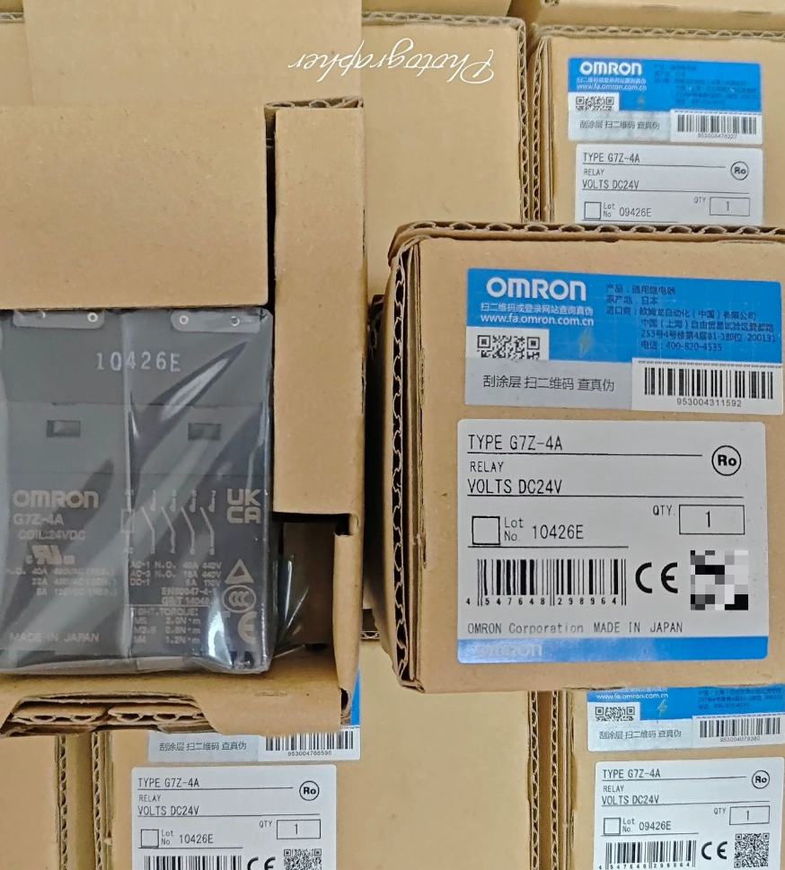

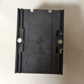
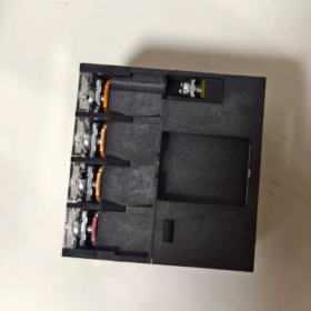
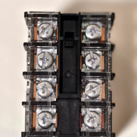
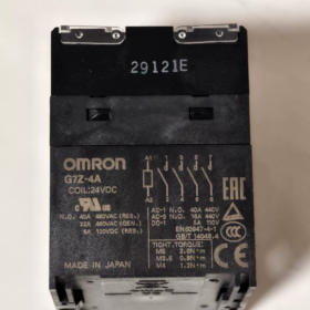
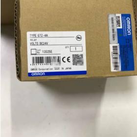
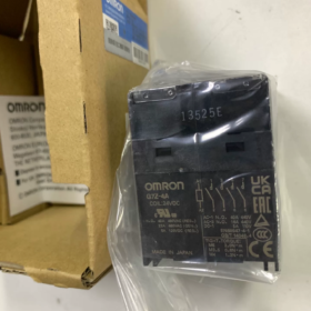
Serie: G7Z Multi-pole Leistungsrelais (Compact Electromagnetic Contactor Type)
Modelldefinition:
G7Z: Seriencode, high-power double-break relay
-4A: 4-pole Normally-Open (4A, 4PST-NO), no normally-open main contacts
Complete part numbers: G7Z-4A DC12/ G7Z-4A DC24; suffix -R denotes revised version; -11Z-R indicates fitted with 1a1b auxiliary contact block
Grundlegende elektrische Spezifikationen
Spule (DC driven)
| Parameter | DC12V | DC24V |
| Nennspulenspannung | DC12V | DC24V |
| Spulenstrom | 308 mA | 154 mA |
| Spulenwiderstand | 39 Oh | 156 Oh |
| Operate Voltage | ≤75% of rated voltage | ≤75% of rated voltage |
| Release Voltage | ≥10% of rated voltage | ≥10% of rated voltage |
| Maximum Permissible Voltage | 110% | 110% |
| Spulenstromverbrauch | ~3.7 W | ~3.7 W |
Hauptkontakte (4-Pol Nr, Doppelbruchstruktur, Ag-alloy contacts)
Widerstandslast: 40A @ AC440V; max. AC480V
Induktive Last (cosφ=0.3): 22A @ AC440V
DC load: 5A @ DC110V
Max. Schaltkapazität: Resistive 17600 VA; Inductive 9680 VA
Terminals: Schraubklemmen; Montage: DIN-Schienenmontage möglich
Abmessungen: 80×100×100 mm; Built-in operation indicator light, enclosed housing
Modellvarianten
- G7Z-4A DC12 / DC24: Grundeinheit, 4 Haupt-Schließerkontakte, keine Hilfskontakte
- G7Z-4A-11Z-R DC24: Haupteinheit 4a + Angebauter Hilfskontaktblock 1a1b für Statusrückmeldesignale
Ältere G7Z-4A-□Z-Modelle werden nicht mehr hergestellt; durch Versionen mit dem Suffix -R ersetzen: G7Z-4A-□Z-R
Typische Anwendungen
Schalten von dreiphasigen Hochleistungslasten mit 380–440 V (Heizungen, Netzteile, Fans)
DIN-Schienenmontage in Schaltschränken, Alternative zu kleinen Schützen; Direkter SPS-DC-Ausgangsantrieb
⚠️ Hinweis: Stromverbrauch der Spule 3,7 W; Berechnen Sie die aktuelle Marge für SPS-Ausgangsmodule. Reduzieren Sie den Kontaktstrom über 40 °C Umgebungstemperatur: Reduzieren Sie 0,7 A pro 1 °C Anstieg.
Ersatzoptionen
- Omron Gleiche Serie: G7Z-4A-xxZ-R (Werksseitig aufgerüsteter Ersatz)
- Schützalternative: 4-Pol kleines AC-Schütz (40 Eine Klasse, Gleichstromspule)
- Inländisches Äquivalent: 4-Pol 40A DC24V Spule DIN-Schienen-Leistungsrelais. Überprüfen Sie die wichtigsten Spezifikationen: Doppelpause, AC440V-Bewertung, Schraubklemmen, Stromverbrauch der Spule.
Häufige Prüfpunkte zur Fehlerbehebung
- Überprüfen Sie, ob die Spulenversorgungsspannung ≥75 % des Nennwerts beträgt; Messen Sie den Spulenwiderstand, um durchgebrannte Spulen zu erkennen
- Hauptkontakterosion: Unter induktiven Lasten von 40 A sinkt die Lebensdauer stark; Verwenden Sie vorzugsweise eine herabgesetzte Schützdimensionierung
- Sorgen Sie in Umgebungen mit hohen Temperaturen für eine ausreichende Wärmeableitung, um eine unzureichende Stromreduzierung zu vermeiden.
OMRON G7Z-4A Montageanleitung
Der G7Z-4A unterstützt die DIN-Schienenmontage und die Panel-Schraubmontage. Obligatorische Montageausrichtung: Spulenanschlüsse nach oben zeigen. Montieren Sie niemals die Anschlüsse verkehrt herum.
- DIN-Schienenmontage (Standard für Schaltschränke)
Kompatible Schiene: Norm DIN EN50022, 35×7,5 mm (TR35-15Fe) Stahlschiene
❗ Nicht kompatibel mit überdicken Schwerlastschienen einiger Hersteller, Gefahr einer unsicheren Verriegelung.
Ausrichtung montieren: Horizontaler Einbau mit Spulenanschlüssen nach oben. Eine vertikale oder umgekehrte Montage ist verboten.
Installationsvorgang: Hängen Sie den hinteren Federclip an der Oberkante der Schiene ein, Drücken Sie nach unten, bis ein „Klick“ das vollständige Einrasten bestätigt.
Anti-Vibrations-Sicherung: Für Umgebungen mit hohen Vibrationen, Bringen Sie auf beiden Seiten Schienenendstopper PFP-M an, um ein Verrutschen oder Verrutschen zu verhindern.
Entfernung: Hebeln Sie die untere Federklemme mit einem Schlitzschraubendreher nach unten und heben Sie das Relais nach oben.
- Panel-Schraubmontage
Befestigen Sie es mit zwei M4-Schrauben durch die Befestigungslöcher am Gehäuse. Das Anzugsdrehmoment beträgt unbedingt 1,2–1,3 N·m. Vermeiden Sie ein zu festes Anziehen (rissiges Gehäuse) oder zu wenig angezogen (Lockerheit).
Halten Sie die Spulenanschlüsse nach oben gerichtet.
Geeignet für kundenspezifische Gehäuse ohne Standard-DIN-Schiene.
- Hilfskontaktblock (G73Z-□Z-R) Montage & Entfernung
Hilfskontaktblöcke liefern Statusrückmeldungen für die G7Z-4A-Basiseinheit:
- Setzen Sie die Blockklauen in die Aussparungen des Relaishauptkörpers ein;
- Nach innen drücken, bis es mit einem hörbaren Klicken einrastet;
- Entfernung: Schieben Sie den Hilfsblock, um Haken und Klauen zu lösen. Hebeln Sie Kunststoffhaken nicht mit Gewalt auf.
- Montagefreiraum & Thermische Anforderungen (Kritisch für Stromreduzierung)
- Halten Sie auf allen Seiten einen Mindestabstand von 5 mm zwischen dem Relaisgehäuse und den metallischen Erdungsflächen des Gehäuses ein;
- Mehrere G7Z-4A nebeneinander: Halten Sie einen Mindestabstand von 30 mm zwischen den Einheiten ein. Eine dicht benachbarte Montage führt zu einer übermäßigen Eigenerwärmung und einer zwangsläufigen Leistungsreduzierung der Kontakte;
- Halten Sie den oberen Bereich gut belüftet; Vermeiden Sie es, wärmeerzeugende Komponenten direkt darüber zu stapeln;
- Reduzieren Sie den Kontaktstrom bei Umgebungstemperaturen über 40 °C.
- Anzugsdrehmoment der Klemmen
| Anschlussschraube | Anzugsdrehmoment |
| Hauptstromanschlüsse (M5) | 2.0-2,2 N·m |
| Spulenanschlüsse (M3,5) | 0.8-0,9 N·m |
Lose Anschlüsse führen bei hoher Belastung zu Überhitzung und Durchbrennen; Die Verwendung eines Drehmomentschlüssels wird empfohlen.
- Strenge Verbote
- ❗ NICHT verkehrt herum montieren (Anschlüsse nach unten zeigen): risk of abnormal mechanical operation and shortened service life.
- ❗ Do NOT mount rotated 90° on side.
- ❗ Do NOT use non-standard over-thick DIN rails.
- ❗ Do NOT touch live terminals while powered; fit terminal safety covers for shock hazard protection.
- Post-installation Checks
- Relay secured firmly without wobble (rail clip or mounting screws fully tightened);
- Auxiliary contact block is securely latched;
- All terminals torqued to specified values;
- Thermal clearances met; no obstructions surrounding the unit.
OMRON G7Z-4A Ambient Temperature Specifications
Betriebsumgebungstemperatur
-25 °C ~ +60 °C, kein Zuckerguss, keine kondensation.
40 A rated contact current applies at ambient ≤45 °C.
High-Temperature Current Derating Rule (Kritisch)
For ambient temperature >45 °C up to 60 °C: reduce continuous allowable current by 0.7 A per 1 °C rise.
Example @50 °C: Max continuous current = 40-(50-45)×0.7 = 36.5 A
Example @60 °C limit: Max continuous current = 40-(60-45)×0.7 = 29.5 A
Same derating applies when G73Z-□Z-R auxiliary contact block is fitted.
Umgebungsfeuchtigkeit
5 % ~ 85 % RH, nicht kondensierend.
Lagertemperatur (Unpowered unit)
Not explicitly listed on datasheet; industrial practice: -40 °C ~ +70 °C, keine Vereisung oder Kondensation.
Design Notes
- Operation at -25 °C is permitted; prevent cabinet condensation; dehumidify cabinet before cold startup.
- Closely-mounted multiple units add self-heating; actual component temperature is higher than cabinet air-sensor reading. Adequate thermal spacing is mandatory.
- Coil resistance increases with temperature. Stellen Sie sicher, dass die Spulenversorgungsspannung unter Hochtemperaturbedingungen ≥75 % des Nennwerts beibehält, um unzuverlässiges Einschalten zu verhindern.
- Nicht über 60 °C Umgebungstemperatur betreiben: beschleunigt Kontakterosion und Spulenalterung.
OMRON G7Z-4A Kontaktkonfiguration
Hauptkontakte der Haupteinheit: 4A (4PST-NO), Vierpoliger Schließer; keine Haupt-Öffnerkontakte
Erklärung des Modellcodes: 4A = 4-polig-All-NO. Alle Kontakte öffnen, wenn die Spule stromlos ist; Alle vier Pole schließen gleichzeitig, wenn die Spule erregt wird.
Kontaktmechanismus: Doppelte Pause. Zwei separate Sollbruchstellen pro Stange, Verbesserte Lichtbogenlöschfähigkeit für Hochspannungs-AC440V-Schwerlastschaltungen.
Kontaktmaterial: Ag-Legierung.
Hauptkontaktbewertungen (für Pol)
Widerstandslast: 40 A @ AC440V
Induktive Last (cosφ=0.3): 22 A @ AC440V
DC load: 5 A @ DC110V
Hilfskontakte (Separater G73Z-□Z-R-Block erforderlich; nicht eingebaut)
| Suffixcode | Hilfskontaktformular |
| ‑20Z‑R | 2A (DPST-NR, 2-Pol Nr) |
| ‑11Z‑R | 1a1b (SPST-NR + SPST-NC, 1NO+1NC) |
| ‑02Z‑R | 2B (DPST-NC, 2‐Pol NC) |
Hilfskontakte verwenden eine Einzelunterbrechungskonstruktion, Maximaler Nennstrom 1A. Nur für Statusrückmeldesignale. NICHT zum Tragen von Hauptstromlasten geeignet.
Querverweis für verwandte Serienmodelle (als Auswahlreferenz)
- G7Z-4A:4A (4-Pol Nr)
- G7Z-3A1B:3a1b (3-NO-Feld +1-NC-Feld)
- G7Z-2A2B:2a2b (2-NO-Feld +2-NC-Feld)
Design-Schlüsselpunkte
- Die G7Z-4A-Basiseinheit verfügt über keine Haupt-Öffnerkontakte. Wählen Sie G7Z-3A1B / G7Z-2A2B, wenn Haupt-Öffnerkontakte erforderlich sind.
- Das Doppelunterbrechungsdesign sorgt für eine hohe Spannungsfestigkeit zwischen den Phasen; gut geeignet zum Schalten von 3-Phasen-Heizungen und 3-Phasen-Lüftern.
- Hilfsblöcke sind ausschließlich für Rückmeldesignale vorgesehen; niemals für spannungsführende Stromkreise verwenden.





NH42-63-318x560.png "Automatische Transferschalter vom Typ CHINT PC (ATS)NH42-63/4SZ")



